CubuSynth Engine - Build Guide PCB V1.1 Jul 2022
STEP 5 (Main PCB)
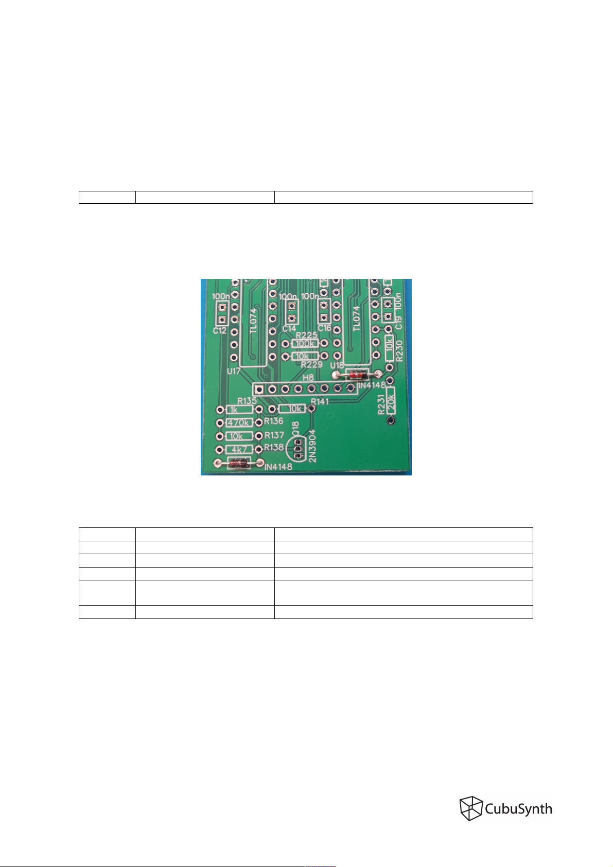
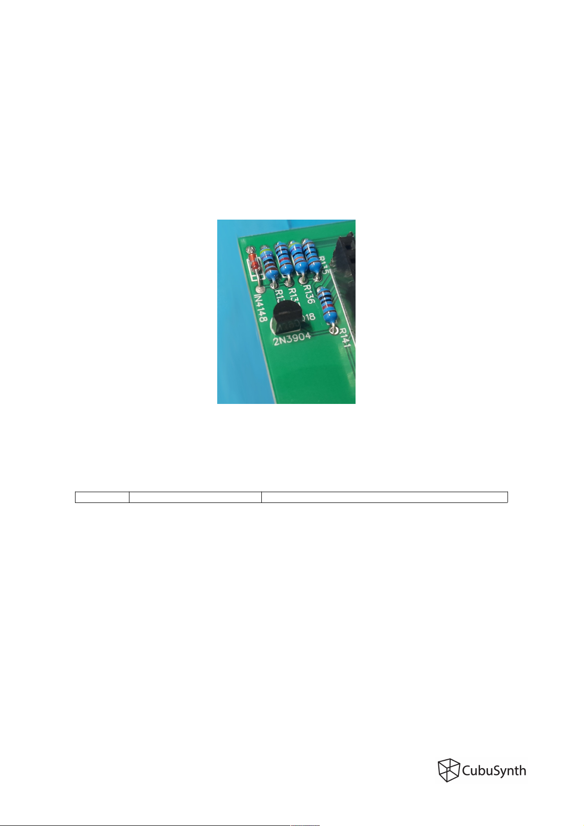
Transistor
Take the 2N3904, put it in place and make sure the orientation is correct. The outline o the
transistor has to match with the silkscreen on the PCB. You can bend the 2 outer legs o each
transistor, so it doesn't all out when turning around the board.
The ootprint is quite small, so stay ocused and don't use too much solder to avoid shorts.
Check your solder joints with a magni ier and/or multimeter when in doubt.
STEP 6 (Main PCB)
IC sockets
Oriantation is important to know how to place the ICs later! The notch should ace upwards,
matching the print on the PCB.
You can use tape to hold them in place, put the other PCB on top, or bend 2 pins o each socket
inwards, so they don't all when turning the board around. Then solder everything.
Page 6