Cumberland EDGE 074-11801 User manual

EDGE Weather Station
Models:
074–11801
User Manual
890–00666
Version 02
Date: 05-03-19
Rev. 02

For more complete information on the product, please refer to the manual on the USB key
provided with your EDGE controller or go to the following web sites:
• AP website: http://www.automatedproduction.com/ap-sales-and-service/ap-
manuals.html
• Cumberland website: http://www.cumberlandpoultry.com/sales-and-service/
manuals.html
Model:
Serial number:
Date Installed:
All information, illustrations, photos, and specifications in this manual are based on the latest
information available at the time of publication. The right is reserved to make changes at any
time without notice.
2890–00666 Weather Station

Contents
Chapter 1 Introduction...............................................................................................................................5
Contact Information .....................................................................................................................5
General Safety Precautions and Usage.........................................................................................7
Terms of Use ..............................................................................................................................8
What to Look for When You Receive Your System .......................................................................10
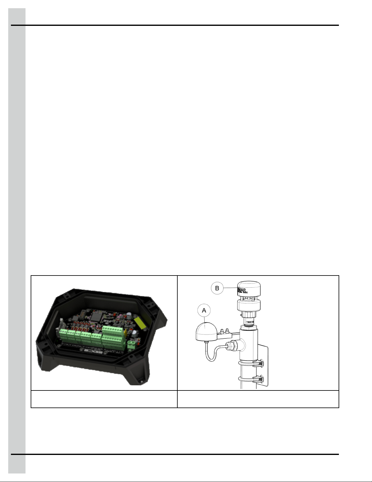
System Overview ......................................................................................................................10
Guidelines on the Ideal Location for Installation ........................................................................... 11
Clearance Around the EDGE Weather Station ............................................................................. 11
Correctly Supporting and Routing Cables....................................................................................12
Grounding Recommendations for the System..............................................................................13
Chapter 2 Basic Connections ..................................................................................................................17
Preparing the Enclosure for Installation ....................................................................................... 17
Mounting the Enclosure .............................................................................................................18
Installing the Weather Station and Rain Sensors..........................................................................19
Power Source Connecting .........................................................................................................24
Connecting the EDGE Weather Station to the Communication Network.........................................25
Connecting the Wires for the Main Weather Sensor (110WX)........................................................27
Connecting the Wires to the Rain Sensor ....................................................................................28
Grounding ................................................................................................................................29
Chapter 3 Maintenance............................................................................................................................31
Inspecting and Cleaning the Enclosure .......................................................................................31
Inspecting and Tightening the Connections .................................................................................31
Guidelines for Inspecting the 110WX Sensor (Weather Station) ....................................................32
Replacing the Humidity Sensor ..................................................................................................33
Inspecting the RG-11 Rain Sensor..............................................................................................34
Chapter 4 Troubleshooting......................................................................................................................37
Appendix A LED Meanings .........................................................................................................................39
Appendix B List of Terminals .....................................................................................................................41
Appendix C Replacement Parts ..................................................................................................................43
Appendix D Technical Specifications .........................................................................................................45
Appendix E Safety Characteristics and Certification ..................................................................................49
Appendix F EC Declaration of Conformity (In Accordance with EN ISO 17050-1 2004) ...............................53
Appendix G FCC Part 15 Statement ............................................................................................................55
Appendix H Innovation, Science and Economic Development Canada Statement......................................57
Appendix I FDA declaration.......................................................................................................................59
Appendix J Reduction of Hazardous Substances ......................................................................................61
Appendix K Disposal and Recycling Information........................................................................................63
Appendix L California Proposition 65.........................................................................................................65
Appendix M China RoHS and EFUP Marking...............................................................................................67
Appendix N Product Material Composition.................................................................................................69
Appendix O Packaging Characteristics ......................................................................................................71
Appendix P Low Voltage Cable Specifications ...........................................................................................73
Appendix Q EDGE Weather Station - Product End-of-Life Disassembly Instructions .................................77
Limited Warranty — N.A. Grain Products ................................................................................83
890–00666 Weather Station 3

NOTES
4890–00666 Weather Station

1Introduction
Topics Covered in this Chapter
▪ Contact Information
▪ General Safety Precautions and Usage
▪ Terms of Use
▪ What to Look for When You Receive Your System
▪ System Overview
▪ Guidelines on the Ideal Location for Installation
▪ Clearance Around the EDGE Weather Station
▪ Correctly Supporting and Routing Cables
▪ Grounding Recommendations for the System
Contact Information
Sales
USA
Automated Production Systems (AP/Cumberland)
1004 East Illinois St.
Assumption, IL 62510 USA
Technical support: 712-239-1011
Phone: 217-226-4449 International phone: 217-226-4401
Fax: 217-226-3540 International fax: 217-226-4420
E-mail: [email protected]
890–00666 Weather Station 5

Chapter 1: Introduction
CANADA & International
GSI Electronics
5200 Armand Frappier Saint-Hubert, Qc
Canada J3Z 1G5
Phone: 1-877-926-2777
Fax:1-866-880-2777
E-mail: [email protected]
Support
USA
Automated Production Systems (AP/Cumberland)
Technical Support: 712-239-1011
Phone: 217-226-4449 International Phone: 217-226-4401
Fax: 217-226-3540 International Fax: 217-226-4420
CANADA & International
GSI Electronics
5200 Armand Frappier Saint-Hubert, Qc
Canada J3Z 1G5
Phone and Technical support: 1-877-926-2777
Fax:1-866-880-2777
E-mail: ddl.mon.techsupport@fr.agcocorp.com
Manufacturer
GSI Electronics
5200 Armand Frappier Saint-Hubert, Qc
Canada J3Z 1G5
6890–00666 Weather Station

Chapter 1: Introduction
WARNING
Warranty is void if this product is used in a manner not specified by the
manufacturer. Every effort has been made to ensure that this manual is complete,
accurate and up to date. The information contained in this manual is subject to
change without notice.
General Safety Precautions and Usage
Safety Symbols
Warning. Read the following text carefully; it contains important information
which, if ignored, may cause the controller to operate improperly
High Voltage. Hazard of electrical shock. Read the message and follow the
instructions carefully
Direct current (DC)
Alternating current (AC)
Protective Earth Ground Terminal, Primarily used for protective earth
terminals.
Terminal connected to conductive parts of a device for the purpose of safety
and is intended to be connected to an external system for protective
grounding
Functional Ground Terminal Primarily used for functional earth terminals
which are generally associated with test and measurement circuits. These
terminals are not for safety earthing purposes but provide an earth reference
point.
Double insulation
NOTE: To emphasize points or remind readers of something, or to indicate minor
problems in the outcome of what they are doing
CAUTION
Failure to follow the instructions can result in damaged equipment or loss of
data or potential problems
DANGER
Failure to follow the instructions carefully can result in serious or fatal injury
IMPORTANT: The following information is of great significance and must be read carefully
890–00666 Weather Station 7

Chapter 1: Introduction
WARNING
Read the following text carefully; it contains important information which, if
ignored, may cause the controller to operate improperly
Tip Shortcut or a faster way of getting to an end result
Safety Messages
DANGER
Turn off the main electrical disconnect switch prior to servicing any of the boxes.
Failure to do so might lead to serious injury or death.
Always use extreme caution when measuring voltage or performing procedures that require a
module to be powered on.
Electrostatic Discharge Prevention When Manipulating a Printed Circuit
Board (PCB)
Electrostatic discharge (ESD) can damage equipment and impair electrical circuitry. ESD damage occurs
when electronic components are improperly handled and can result in complete or intermittent failures.
Always follow ESD on a PCB-prevention procedures when you remove and replace components. Ensure
that the chassis is electrically connected to earth ground. Wear an ESD-preventive wrist strap, ensuring
that it makes good skin contact. Connect the grounding clip to an unpainted surface of the chassis frame
to safely ground unwanted ESD voltages. To guard against ESD damage and shocks, the wrist strap and
cord must operate properly. If no wrist strap is available, ground yourself by touching the metal part of the
chassis.
For safety, periodically check the resistance value of the antistatic strap, which should be between 1 and
10 megohm (Mohm).
Terms of Use
Read and follow all installation, operation, and maintenance information carefully before using the prod-
uct. Refer to the user documentation for complete product specifications. If the product is used in a
manner not specified, the protection provided by the product warranty will be void.
Using the Product According to Your Function
A responsible body is an individual or group responsible for the use and maintenance of equipment, for
ensuring that the equipment is operated within its specifications and operating limits, and for ensuring
that operators are adequately trained.
Operators use the product for its intended function.
Maintenance personnel perform routine procedures on the product to keep it operating properly. At this
level, all procedures whose do not touch high voltage. The maintenance personnel can work on high volt-
age only if they have the competences as an electrician.
Service personnel are trained to work on live circuits, perform safe installations, and repair products. Only
properly trained service personnel may perform installation and service procedures. (In other words: elec-
tricians, Service personnel employed by or active in an organization, business, or service).
8890–00666 Weather Station

Chapter 1: Introduction
General Safety Usage
Follow the guidelines given below for safe usage of the product:
• Installation must only be performed by qualified service personnel
• Carefully read all instructions
• Comply with local and national safety codes
• Repairs must only be performed by qualified service personnel
• When replacing the fuses, use only the same type and same rating as specified
• Make sure the unit is disconnected from AC Power when servicing
• Do not try to operate the system if it is damaged. Disconnect the Power from the units and call your
local service representative
• Do not operate while condensation is present
• Use of the system in a manner not specified by these instructions may impair the safety protection
provided by the system. Do not operate the system outside its rated supply voltages or environmen-
tal range
• Omission to read the installation and user manuals or to comply with the warnings and references
contained herein can result in serious bodily injury or damages to the controllers
• Do not insert metal objects into the connectors
• Use the system only as specified, or the protection supplied by the product can be compromised
• Follow all installation and maintenance recommendations and consider all provided information
regarding product specifications and limitations
• Do not use the system if it does not operate correctly
• The enclosures must be closed and locked at all times, particularly when operating the system
• Use only specified replacement parts
890–00666 Weather Station 9

Chapter 1: Introduction
What to Look for When You Receive Your System
Shipment Contents:
• 1 X EDGE Weather Station module
• 1 X EDGE 110WX Weather Station
• 1 X EDGE 110WX Weather Station 98 Ft. (30 m) cable
• 1 X Rain sensor unit with 98ft (30 m) cable, outdoor use
• Weather Station brackets and hardware kit
• 1 X Quick guide
Damage Inspection
Your system and its components were carefully inspected both electrically and mechanically before ship-
ment. After unpacking all items, check for any obvious signs of physical damage that may have occurred
during transit. Report any damage to the shipping agent immediately. Save the original box for possible
future shipment.
Returning the Unit for Repair
If you must return the system for repair, carefully package the system in its original box or an equivalent,
and follow these instructions:
1. Call the customer service department to get a Return Material Authorization (RMA) number. Have
on hand the system’s serial number and date code found on the system’s main board.
2. Indicate clearly that the box is to be given to the repair department and attach a copy of the RMA
number on the shipping label.
System Overview
EDGE Weather Station Rain Sensor RG-11 (A) and Weather Station 110WX (B)
10 890–00666 Weather Station

Chapter 1: Introduction
EDGE Weather Station — The EDGE Weather Station provides the outside environmental parameters
to the ventilation controller which will correctly manage the ventilation system according to the outside
parameters. The information from the sensors is transmitted by the Weather Station to the ventilation con-
troller by the RS-485 bus. The EDGE Weather Station can measure wind speed, wind direction, outside
temperature, outside humidity, and atmospheric pressure.
The EDGE Weather Station has these main features:
• 1 x Weather Station input (Can bus) with 15Vdc output
• 1 x Rain sensor input with 15Vdc output
• 2 x RS-485 Bus (Automation and Safety)
• 2 x DC supply inputs by RS-485 Bus (Automation and Safety)
• 1 x AC supply input
The EDGE Weather station has this configuration according to the ventilation controller.
Guidelines on the Ideal Location for Installation
Operating Environment
• To avoid exposing the system to harmful gases or excessive humidity, install the EDGE Weather
Station in a corridor or a room dedicated to electronic controllers.
• The ideal ambient temperature is between 20 °C and 25 °C (68 °F - 77 °F). The temperature should
not go lower than 0 °C (32 °F) and should not exceed 40 °C (104 °F).
• Ensure there is sufficient ventilation around the unit.
• Install the EDGE Weather Station far from sources of vibrations and where they are not likely to get
bumped.
IMPORTANT: If you are not planning on installing the system immediately, store the units in a cool dry
place.
Requirements for the Mounting Structure
Fix the enclosures into the supporting structure behind a drywall. If this is not possible, consider the addi-
tion of a wood frame on which the enclosure could be screwed.
Clearance Around the EDGE Weather Station
The following minimum clearances must be respected around the EDGE Weather Station enclosure.
890–00666 Weather Station 11

Chapter 1: Introduction
Figure 1-1 Minimum clearance
Correctly Supporting and Routing Cables
Properly supporting and routing the cables helps avoid electromagnetic interference and wire damage.
Rigid conduits up to 1 inch (25.4mm) can be used for connection to the EDGE Weather Station.
Cable Connectors
NOTE: Nylon cable glands are permitted for cable or wire fastening.
WARNING
Use watertight compression cable glands rated IP66 for each cable used.
WARNING
Use silicone to seal the cable gland rated IP66 if more than one cable is use in the
same cable gland.
WARNING
The warranty is void if the product enclosures are not sealed correctly and the
installation does not respect the manufacturer recommendations.
WARNING
Ensure all cables enter through the bottom of the plastic enclosure. Do not make
holes on the top or on the sides of the enclosures. Be careful not to damage the
electronic cards located inside the enclosure when drilling at the bottom of the
enclosure.
NOTICE
The use of flexible tube with water and dust tight connectors at both ends is
acceptable.
Cable Support
Support the cables with clips or cable trays whenever possible to avoid damage at the connection points.
12 890–00666 Weather Station

Chapter 1: Introduction
Cable Routing
NOTICE
Never run low voltage (24V and less) wires like communication wires, inputs or
sensors wires in the same conduit as a High Voltage (Power) wire.
When low voltage cables run parallel to high voltage cables (120/230/380 VAC), place them at a distance
of at least 300 mm (12 inches) from each other to avoid electromagnetic interference
If low voltage cables cross high voltage cables, make sure they cross at an angle of 90° to minimize elec-
tromagnetic interference.
WARNING
Do not use rigid conduits over 1 inch (25.4mm) for the EDGE Weather Station.
Grounding Recommendations for the System
A correctly grounded system protects your equipment from electrical surges and spikes.
CAUTION
Each module must have its own ground connection from a common junction box.
Do not run the earth ground cable between the modules.
NOTICE
The ground resistance levels must comply with local and national electrical codes.
IMPORTANT: If outdoor connections are used, mount the enclosure as close as possible to the entry
point of the outdoor wiring.
IMPORTANT: An improper ground connection voids the system’s warranty.
Insert the rod into the ground until a few inches of the tip is left above ground level. Attach the cable to the
rod tip with an appropriate connector. Attach the other end of the cable to a breaker box or a junction box
near the main enclosure.
890–00666 Weather Station 13

Chapter 1: Introduction
Figure 1-2 Grounding installation depending on bedrock depth
3 m
(10 FEET)
0.6 m
(2 FEET)
0.6 m
(2 FEET)
> 1.2 m
(47 IN.)
<1.2 m
(47 IN.)
3 m (10 FEET)
3 m (10 FEET)
METALLIC ROD BEDROCK
• If the bedrock is more than 3 meters (10 feet) below ground level, drive the grounding rod vertically
3 meters (10 feet) into the ground.
• If the bedrock is more than 1.2 meters (47 inches) below ground level, drive the rod into the ground
to bedrock level and bury the remainder horizontally at least 0.6 meters (2 feet) below ground level.
• If the bedrock is less than 1.2 meters (47 inches) deep, bury the rod horizontally at least 0.6 meters
(2 feet) below ground level.
NOTE: Refer to your local regulations and practices if an adequate grounding installation isn’t possible.
Rod Specifications for Grounding
The rod specifications are guidelines only. Refer to your national and local regulations for compliance
criteria.
Table 1-1 Grounding rod specifications
Item Description
Material Metallic, normally steel core.
Rod surface The surface must be clean. It cannot be coated with paint, varnish or any non-conducting
substance.
Minimum diameter 16 mm (5/8 inches)
Minimum length 2440 mm (8 feet)
Cable Specifications for Grounding
The cable specifications are guidelines only. Refer to your national and local regulations for compliance
criteria.
Table 1-2 Grounding Cable Specifications
Item Description
Certification and
type
CSA, TEW type.
14 890–00666 Weather Station

NOTES
16 890–00666 Weather Station

2Basic Connections
Topics Covered in this Chapter
▪ Preparing the Enclosure for Installation
▪ Mounting the Enclosure
▪ Installing the Weather Station and Rain Sensors
▪ Power Source Connecting
▪ Connecting the EDGE Weather Station to the Communication Network
▪ Connecting the Wires for the Main Weather Sensor (110WX)
▪ Connecting the Wires to the Rain Sensor
▪ Grounding
Preparing the Enclosure for Installation
Preparing the equipment before mounting it to the wall facilitates manipulation and ensures all parts are
ready to be installed.
Before You Begin
Wires are separated into two groups: low voltage and high voltage in the plastic enclosure and the
conduits.
NOTE: The rigid conduits use is allowed. The use of rigid conduits is allowed up to 1 inch (25.4mm) for
the EDGE Weather Station (inside part).
1. Unscrew the screws from the cover and remove the cover
2. Drill a hole the size of the your cable connectors or your rigid conduits at the bottom side of the
enclosure.
3. Remove the plastic fragments.
4. Install the cable connectors or rigid conduits adaptor to the bottom of the enclosure.
5. Close the enclosure by screwing the cover.
IMPORTANT: Leave the rated clearances to allow the cover to be removed for maintenance
Remember
Do not mount the enclosure directly onto the drywall. If the supporting structure behind the drywall
cannot support the enclosure, solidify it by adding a wooden or metal frame.
890–00666 Weather Station 17

Chapter 2: Basic Connections
Mounting the Enclosure
Securely mounting the enclosure to the wall in the ideal location allows for an optimal use of the system.
Before You Begin
NOTICE
When using outdoor connections, mount the enclosure as close as possible to the
entry point of the wiring
IMPORTANT: Mount the system into a wooden or metal frame. Do not mount the system directly into the
drywall
NOTE: Install the enclosure (EDGE Weather Station) by placing the text at the right sense when you look
at in front of the enclosure. The widest side must be at the horizontal side.
Consult the wiring diagram about the wires length restriction between devices (outside sensors and other
enclosures of the system)..
NOTE: AP/Cumberland recommends this kind of screw: Deck Screw for Wood
1. Place the enclosure at a height that you can maintain the EDGE Weather Station.
2. Install the first screw at the upper corner left.
3. Use a level to place the enclosure at the level.
4. Install the second screw at the lower corner right.
5. Install the third screw at the lower corner left.
6. Install the last screw.
IMPORTANT: Leave clearance rated in the last section to allow the cover to be removed for
maintenance.
18 890–00666 Weather Station

Chapter 2: Basic Connections
Installing the Weather Station and Rain Sensors
The sensors for the Weather Station kit must be mounted to a building or structure to place it at above
and away from interference.
Before You Begin
These instructions cover the installation of the EDG-187 Weather Station that includes the hardware and
mounting kit EDG-184.
What You Should Know
The Weather Station sensor and Rain Sensors will need to be mounted above and away from any
obstacles that would interfere with communication. The maximum cable length for the Weather Station
Sensor and the Rain Sensor cable is 98 Ft., (30 m). Therefore, the EDGE Weather Station should be
mounted within 98 Ft. (30 m) of the sensor. The sensors must be mounted 5 Ft. (1.5 m) above the roof or
structure edge.
1. Determine the length of pipe needed for the weather station to be mounted 5 Ft. above the roof or
structure edge and also long enough to reach where the pipe will enter the building.
2. Cut a section of 1-1/2” schedule 80 PVC pipe (not included) to the length needed.
3. Cut a 6” length of 1-1/2” schedule 80 PVC pipe to pass through the hole into the building.
4. At a location that is convenient to run the electrical wires to the controllers, use a hole saw to drill a
2” hole into the outside wall of the building.
5. Install the Nipple (3) into the 1-1/2 inch Bushing (4).
Use Teflon Tape to seal the threads.
6. Install the Cable Swivel Connector (2) onto the Nipple (3).
Use Teflon Tape to seal the threads.
890–00666 Weather Station 19

Chapter 2: Basic Connections
Figure 2-1 Weather Station Sensor Assembly
7. Install the Cable (2) to the Weather Sensor.
The cable rests inside a swivel connector, this will allow the cable to stay stationary as you twist the
connector onto the Weather Sensor.
8. Position the Weather Sensor (1) with the Alignment notch pointed toward true North. To do this,
loosen the Swivel Connector (2) and move the Weather Sensor until the notch is facing North, then
tighten the Swivel Connector (2).
IMPORTANT: Hand tighten only. Tighten or align the Weather Station by grasping the lower housing
below the reflector plate.
20 890–00666 Weather Station
Table of contents
Other Cumberland Weather Station manuals