CUOGHI NEB 6500 User manual

F3025 - NEB 6500
F3026 - NEB 6500 R
READ AND SAVE THESE INSTRUCTIONS
Adiabatic humidier

F3025 - NEB 6500

F3026 - NEB 6500 R

4M898-3_GB_letter
NEB 6500 and NEB 6500 R
Table of Contents
1 Technical features............................................................................................... 5
1.1 Main features .................................................................................................................................................... 5
1.2 Dimensions and weights................................................................................................................................ 5
1.3 Description of the components .................................................................................................................... 5
2 Introduction......................................................................................................... 5
2.1 General safety rules.......................................................................................................................................... 5
3 Installation .......................................................................................................... 6
3.1 Materials supplied............................................................................................................................................ 6
3.2 Preliminary operations ................................................................................................................................... 6
4 Positioning........................................................................................................... 7
4.1 Wall installation................................................................................................................................................ 7
4.2 Hanging installation ....................................................................................................................................... 8
4.3 Electrical connections...................................................................................................................................... 9
4.3.1 Wiring diagram.......................................................................................................................................... 9
4.3.2 Cabling......................................................................................................................................................... 9
4.4 Hydraulic connections .................................................................................................................................... 9
4.5 Final operations..............................................................................................................................................10
5 Operation & Control ......................................................................................... 10
5.1 Preliminary checking..................................................................................................................................... 10
5.2 Starting............................................................................................................................................................. 10
5.3 Stopping ...........................................................................................................................................................10
6 Electronic control.............................................................................................. 10
6.1 The electronic board...................................................................................................................................... 10
6.1.1 Dip switches..............................................................................................................................................11
6.2 Adjusting the humidication capacity...................................................................................................... 11
6.3 The washing/reset cycle................................................................................................................................11
7 Maintenance ..................................................................................................... 12
7.1 Cleaning the air lter..................................................................................................................................... 12
7.2 Drain siphon.................................................................................................................................................... 12
7.3 Feeding solenoid valve..................................................................................................................................12
7.4 Performing the washing/reset cycle .......................................................................................................... 13
8 Storing................................................................................................................ 13
8.1 Points to check before and after a long period of inactivity ................................................................ 13
8.1.1 Before .........................................................................................................................................................13
8.1.2 After ........................................................................................................................................................... 13
9 Disposal of the product.................................................................................... 13

5
M898-3_GB_letter
NEB 6500 and NEB 6500 R
1.1 Main features
NEB 6500 NEB 6500R
Atomizing capacity 3.3 - 15.8 lbs/hour 3.3 - 15.8 lbs/hour
Electric power supply 120 V, 60 Hz 120 V, 60 Hz
Rated Current 3.0 A 3.8 A, 70 W
Air Flow 164.8 cfm 164.8 cfm
Water Supply Pressure 14.5 - 145 psi 14.5 - 145 psi
Supply Tank Water Content 0.12 lbs 0.12 lbs
Protection Rating IPX4
Operating Temperature +33.8°F … +95°F +28.4°F … +95°F
Operating humidity 0 … 100% R.H. n.c. 0…100% R.H. n.c.
Tab. 1 - Main features
1.2 Dimensions and weights
Pic.1 - Dimensions
NEB 6500 NEB 6500R
Weight 38.8 lbs 43.2 lbs
Tab. 2 - Weights
1.3 Description of the components
Pic.2 - Main components
1Air diuser 5Suction cone
2Electric motor 6Air lter
3Rotating disk 7External junction box
4Heating resistance (only 6500R) 8Internal junction box
Tab. 3 - Main components
e NEB 6500 is an air humidier and operates on the
principle of water atomizing by centrifugation. e ma-
chine must be fed with tap or demineralized water.
e NEB 6500 operation is controlled by a circuit board
that runs the normal machine operations and also the reg-
ular automatic washing cycles of the supply tank to prevent
stagnant water from depositing inside the machine, pre-
venting the growth of bacteria that is dangerous to human
health.
e machine can operate down to a temperature of
+33.8°F. e anti-freeze device allows NEB 6500R to
operate down to a temperature of 28.4°F.
2.1 General safety rules
ATTENTION! Please read these instructions carefully! To
reduce the risk of re, electrical shock or injury:
»READ this entire manual before installation or mainte-
nance.
»Turn machine o.
»DISCONNECT all electrical power completely.
»e machine must be connected to a power supply via

6M898-3_GB_letter
NEB 6500 and NEB 6500 R
the control panel and in compliance with all local and
federal regulations.
»Always DISCONNECT the electrical power supply at
the main cuto switch on the main control panel. Verify
the unit has no power with a voltage tester.
»Make sure no tools or extra parts have been left in the
machine prior to reinstallation and powering up the
unit.
»Installation and maintenance of the machine must be
done by expert and qualied personnel, capable of car-
rying out the work according to the instructions found
in this manual.
»is machine has been designed to humidify the air; it
is not advisable to use the machine for anything other
than humidity control.
»Any use other than that described in this manual is
to be considered improper, potentially damaging and
dangerous.
»Carefully keep these instructions for future reference.
is humidier is NOT intended for people, children
included, with limited physical or mental capabilities or
without enough experience concerning the use of it. Keep
it away from children and animals.
3.1 Materials supplied
e following materials are supplied with the machine.
Check that all the materials listed below are in the pack
before starting work.
»N.1 humidier mod. NEB 6500 or NEB 6500R.
»N.1 installation manual.
»N.4 expansion plug with screws.
»N.1 brackets for wall mounting.
»N.3 brackets for hanging installation.
»N.1 screw M6×20 EX6 with washer.
»N.1 Water supply pipe 59” long, with connectors G¾.
»N.1 water drain pipe 59” long and 0.39” i.d..
»N.2 cable ties.
3.2 Preliminary operations
To make the NEB 6500 operative you need:
• An electrical control box with a 120 V circuit for
power with a ground connection and protection
devices.
Installation must comply with the safety requirements of
the local regulations in force.
• Water supply connection.
• Water drain connection.
It is advisable to carry out the operations listed below before
starting the actual installation.
First, connect the hydraulic inputs under the rear bracket as
shown in Pic. 3 .
Pic.3 - Main hydraulic connections
Refer to Pic. 3 and:
»Connect the supplied pipe, going to the water discharge
drain A, to the discharge elbow bend B.
»Connect the extremity Cof the water-loading pipe,
supplied, to the supply solenoid valve D.
NOTE: the above operations can also be performed out
with the machine already installed.
e water connection to the water load line must be made
with a set of brand new gaskets: any old gasket cannot be
reused and must be replaced.

7
M898-3_GB_letter
NEB 6500 and NEB 6500 R
e NEB 6500 must be installed in a horizontal position,
with the air lter turned downwards, o the ground. Any
other position will compromise the proper operation of the
machine.
Pic.4 - Inclination
To allow maintenance to be carried out when necessary and
also for the correct operation of the machine, the minimum
advised distances must be respected when positioning the
humidier. Depending on the type of installation that will
be adopted, choose the most opportune position for humid-
ifying the room.
Pic.5 - Minimum distances
A B C D
Distance [inches] ≥40 ≥20 ≥60 ≥120
Tab. 4 - Minimum distances
4.1 Wall installation
To install the humidier on the wall, use the bracket and
the four screws with screw anchors supplied with it. e
bracket can be used as a template to mark the holes on the
wall. Respect the distances, as indicated in par. “4 Position-
ing”, and make sure that the bracket is level before drilling
the holes.
Pic.6 - Wall mounting bracket
Make sure that the wall can support the machine under
operating conditions and that the screws are the right
ones for that type of wall.
»Drill four 5/16” holes, 1.75 inches deep, in the wall as
shown in Pic.6.
»Clean out the inside of the holes.
»Insert the four screw anchors while keeping the two
expansion wings in a vertical plane.
»Fasten the bracket.
e bracket must be tted as in Pic.6.
Pic.7 - ree steps for wall mounting positioning.
Once the bracket has been xed to the wall with the four
screws, carry out the following operations, as indicated in
Pic.7:
1. Lift the machine and tilt it slightly towards the wall.
2. Move the machine until the brackets t into place prop-

8M898-3_GB_letter
NEB 6500 and NEB 6500 R
erly.
3. Let the machine rotate, while guiding it, to the horizon-
tal position: at this point the brackets should be perfect-
ly coupled and interlocked.
Check that the two brackets are correctly coupled on both
sides before leaving the humidier (see detail on Pic.8).
Pic.8 - Rear bracket safety screw.
4. Insert the safety screw supplied that joins the two
brackets and that prevents the machine from getting
dislodged accidentally (see Pic.8).
4.2 Hanging installation
Hanging installation is done with the supplied brackets.
ree supporting chains, from which to hang the machine,
must be prepared as follows:
e chains must hang down as straight as possible and be
attached to hooks that can withstand the weight of the
machine (see “Tab. 2 - Weights”)
Pic.9 - Hanging chain sample
Use metal chains, preferably steel chains: chain material
should not be aected by humidity. Respect the minimum
distances indicated in Pic.5.
Disassemble the rear bracket A, for wall installation, as
shown in Pic.10, by unscrewing the four screws V. en
remove the screw Sthat xes the external junction box.
Pic.10 - Wall mounting bracket removal
Now ve (5) screws should be available (4 screws removed
from the plate A, and one safety lock screw supplied) each
with its own washer.
e bracket Athat has just been disassembled, must be
kept for future installation.
Ret two screws V into the holes Findicated in Pic.10
Use three screws V to fasten the brackets L, for hanging
installation as shown in Pic.11.
Pic.11 - Assembling the three hanging brackets
Hook the machine to the chains and at the same time check
that it is in a horizontal position.
e brackets are set to allow the removal of the lter so
that normal maintenance operations can be performed
without having to unhook the machine from the support-
ing chains.

9
M898-3_GB_letter
NEB 6500 and NEB 6500 R
4.3 Electrical connections
Installation provides for the utilization of an ON/OFF
humidistat that controls starting and switching o the
humidier: it is, however, possible to use a simple ON/OFF
contact; the only dierence is that the machine must be
started and stopped manually. is choice however does not
in any way inuence the installation procedure described
below.
Installation must provide a separator switch for the ap-
pliance on the electric power supply, as shown in Pic.12.
Installation of a 2.5 amp slow blow fuse is necessary for
the start-up of the motor.
4.3.1 Wiring diagram
Pic.12 - Wiring diagram
1. External humidistat (not supplied).
2. Floating device.
3. Electric motor.
4. Solenoid valve.
5. Heating resistance (only on 6500R)
6. Temperature probe
7. Electronic board
8. Line protection (not supplied)
4.3.2 Cabling
e exible lead that is used for the electric connections,
must be at least protected by an ordinary PVC sheath
and respect 227 IEC 53 standards (CENELEC H05VV-F or
H05VVH2-F or better)
With reference to Pic.13:
»Remove the cover of the external junction box by un-
screwing the four screws. In the box there are two cable
clamps that will be used to pass the power cable Pand
the humidistat cable H.
»Pass the power cable through the cable clamp P.
»Fasten the neutral and phase (live) wires to the terminals
Land Wand the ground wire to the ground terminal.
Pic.13 - External junction box opened.
»Pass the cable of the humidistat through the cable gland
Hand connect the two wires to the H-H terminals. e
cable holder is tted with a special plug that is suggested
to keep safe for an eventual future use.
»Close the junction box.
Do NOT apply any voltage to the H-H contacts. e elec-
tronic board checks the status OPENED or CLOSED of the
H-H contacts to start and stop the humidier.
4.4 Hydraulic connections
e installation of the humidier also needs the water
supply and drainage pipes connected. e pipes supplied
must be connected to the machine as explained in par. “3.2
Preliminary operations”.
Pic.14 - Hydraulic connections
e supply pipe Asupplied has a threaded bushing G¾ at
both ends: connect the free end (the straight one) directly

10 M898-3_GB_letter
NEB 6500 and NEB 6500 R
to a water tap B, or to an extension. It is advisable to install
a mechanical lter Cdown-line of the tap B, as shown in
Pic.14.
For the water drain use the plastic pipe Dsupplied or one
that is similar having a 0.39 inches internal diameter. e
pipe must be installed as shown in Pic.14 with a minimum
slope of 10°, to guarantee the correct drainage of the water.
A siphon Emust be on the main drain and not on the
drainpipe connected to the machine.
To guarantee regular drainage of the water, make sure
that the drainpipe has a slope and is straight, without any
bends or constrictions. e end of the drain tube must be
“in air” to prevent any back pressure.
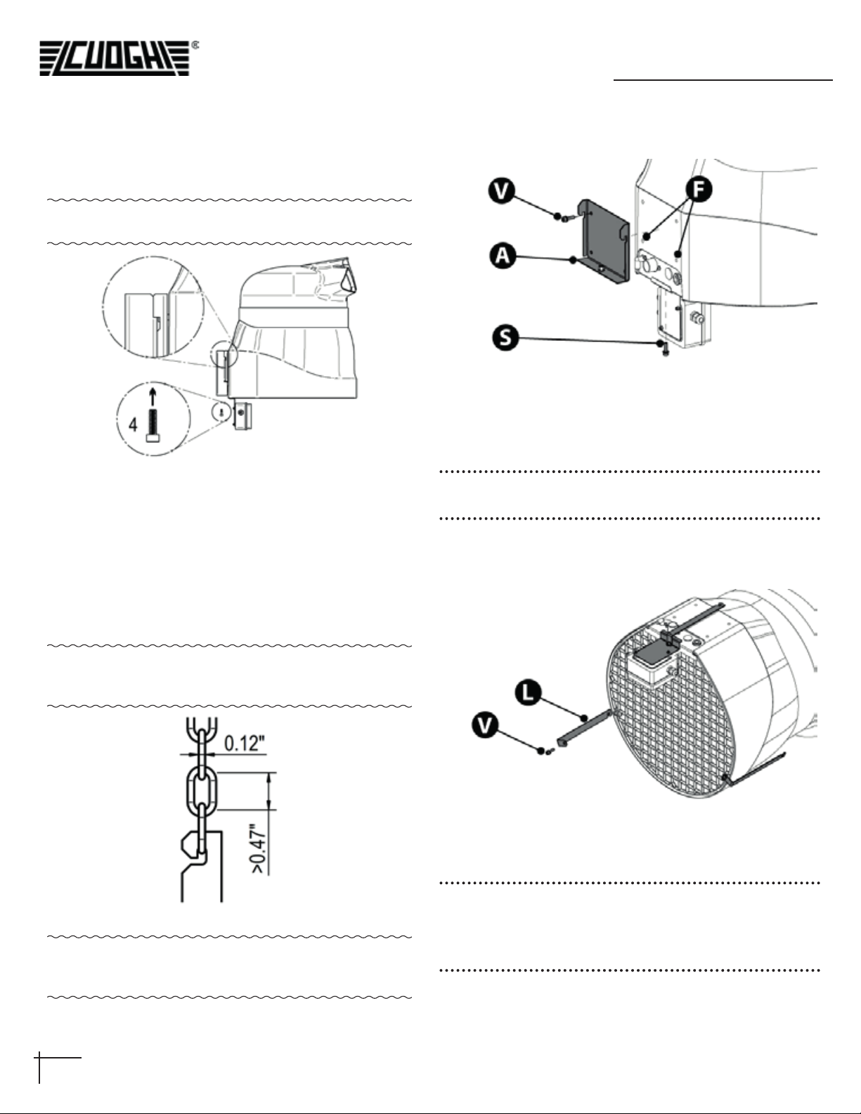
Pic.15 - Details of the end of the drain tube.
WARNING! Any failure in the drainage can cause water
dripping from the humidier.
4.5 Final operations
»Direct the outlets of the air diuser. To do this, loosen
the screw that holds the diuser on top of the machine,
and turn the diuser: at the end of the operation block
the screw again.
»Check that the hydraulic connections have been prop-
erly installed. Open the water supply tap and check that
there are no leaks along the supply circuit
5.1 Preliminary checking
Before starting up the humidier check that:
1. All the connections, both electrical and hydraulic, have
been done according to the instructions found in this
manual.
2. ere are no leaks.
3. e air lter is tted.
4. e water supply tap is open.
5. e distribution inlets are correctly positioned.
WARNING: prolonged use of the machine without water
supply can seriously damage the solenoid valve.
5.2 Starting
To start the humidier turn on the main switch. e
machine will perform a washing cycle lasting about one
minute, as described in detail in par. “6.3 e washing/reset
cycle”. At the end of the cycle, if the humidistat contact is
closed, the humidier starts the motor and water atomiza-
tion begins.
IMPORTANT: e humidier will start to atomize the
water only if the H-H contact is closed.
During operation check if the water is drained regularly. If
it should be necessary to adjust its humidication capacity,
follow the instructions indicated in par. “6.2 Adjusting the
humidication capacity”.
WARNING: if the humidier works in a room with over
saturated humidity the air lter can impregnate reducing
the air ow. Use an humidistat or a timer to avoid this
situation.
5.3 Stopping
To stop the humidier:
1. Take the humidistat to the minimum % R.H. value so
that the corresponding ON/OFF contact is opened.
2. Wait for about one minute to give the machine the time
to carry out the washing cycle.
3. Open the main electrical power switch;
4. Close the water supply tap.
WARNING: if the main switch is opened while the machine
is atomizing the electronic board will NOT perform the
washing cycle and the basin will NOT be emptied.
6.1 e electronic board
e operation of the NEB 6500 is controlled by the elec-
tronic card, that has the following functions:
»Adjustment of the humidication capacity.
»Starting and stopping of the washing/reset cycle.
e regulation of the capacity is made with dip-switches.

11
M898-3_GB_letter
NEB 6500 and NEB 6500 R
Pic.16 - e electronic board
6.1.1 Dip switches
e electronic board of Pic.16 regulates the capacity of the
dehumidier with dip-switches according with Tab. 5.
Tab. 5 - Dip switches
NOTE: the values are indicative. By default the dip switch-
es are set for maximum capacity.
6.2 Adjusting the humidication capacity
Adjustment can be done during the installation phase, or
later if, for example, machine operation is to be adapted to
the variations of the environmental conditions in the envi-
ronment where it has been installed. In this case, proceed as
follows:
»Perform the stopping procedure as in par. “5.3 Stop-
ping”.
»Remove the air lter by unscrewing the three screws that
hold it.
»Remove the electrical connection box by releasing the
spring.
»Open the electric connection box and adjust the posi-
tion of the dip switches according to its needs.
»Close the electric connection box and place it back in its
position with the spring.
»Close the machine and make the checks as described in
par. “4.5 Final operations”.
»Start the humidier again.
6.3 e washing/reset cycle
e electronic card of the NEB 6500 is programmed to
carry out a washing/reset cycle each time:
»e machine is started with the main switch.
»e humidistat closes the H-H contacts because the
necessary %R.H. conditions have been reached.
e scope of this cycle is to prevent water depositing in the
machine when it is not in operation, in this way preventing
the proliferation of bacteria.
e cycle has a xed duration, and consists in:
»Exclusion of the motor, and a 40-second waiting period.
is waiting period gives the motor (and thus the fan/disk
unit) the opportunity to stop completely, and give the water
in the machine time to collect at the bottom of the basin.
»Enabling the water loading solenoid valve.
e water enters the basin until the level sensor trips.
»Wait for the level sensor status change.
e level sensor contact status changes when the water level
rises inside the basin.
»Keeping the water loading solenoid valve enabled for 10
seconds after the level sensor has tripped.
In this way the water level in the basin exceeds that of
normal operation and the siphon is primed: this will drain
all the water out of the basin.
»Disabling the loading solenoid valve and waiting for a
xed time.
is time period is needed to make sure that all the water
in the basin is drained o.
»End of the reset cycle.
At the end of the reset cycle the machine waits for the hu-
midistat H-H contact to be closed or, if it is already closed,
starts the machine and begins to humidify.

12 M898-3_GB_letter
NEB 6500 and NEB 6500 R
e NEB 6500 is designed to guarantee ecient and fault-
less operation for a long time. It is however, necessary to
carry out some simple maintenance operations, how often
they are carried out depends on the environmental condi-
tions in which the NEB 6500 operates and on the quality of
the water supply.
By using RO water the maintenance frequency is drasti-
cally reduced because of the lower quantity of minerals
dissolved in it.
ATTENTION: Before carrying out any maintenance stop
the humidier as described in par. “5.3 Stopping” then
wait for the machine to come to a perfect standstill. Keep
to the general safety rules found in par. “2.1 General safe-
ty rules”. Before starting the machine again, duly check
everything as described in this manual.
7.1 Cleaning the air lter
Pic.17 - air lter.
e lter must be cleaned periodically, since the accumula-
tion of dirt and dust reduces air delivery and so the ecien-
cy of the machine.
»Remove the lter by unscrewing the three screws hold-
ing it.
»Separate the two plastic grids Afrom the lter material
B;
»Clean the lter Bwith a vacuum cleaner or immerse it
in slightly soapy water, and rinse: dry without wringing.
Filter MUST BE COMPLETELY DRY before reinstalla-
tion.
ATTENTION: never enable the humidier without the air
lter tted! e air lter is composed of three pieces that
must be assembled in such a way that the lter material B
is enclosed between the two plastic grids A (Pic.17).
7.2 Drain siphon
It may be necessary to periodically clean the drain siphon A
Pic.18: an accumulation of dirt inside it could compromise
its operation. For best results check the syphon when clean-
ing air lter. When it needs cleaning do the following:
Pic.18 - e siphon
»Remove the air lter.
»Slip out pipe Bfrom the siphon A.
»Unscrew the screws C.
»Remove component A.
»Clean both piece Aand the hole in which it is inserted,
then ret everything.
7.3 Feeding solenoid valve.
e drain solenoid valve is tted with an input lter that
must be checked and cleaned periodically.
Pic.19 - Solenoid valve water lter cleaning
To reach the lter, the pipe connection A of the supply pipe
must be unscrewed: the lter is found inside the threaded

13
M898-3_GB_letter
NEB 6500 and NEB 6500 R
bushing B of the solenoid valve.
If cleaning becomes too frequent, it is advisable to install a
cartridge lter on the machine water supply line (see: par.
“4.4 Hydraulic connections”).
7.4 Performing the washing/reset cycle
»Check that the cycle is done periodically.
To check, carry out the following procedure:
»Detach the end of the drainpipe not attached to the ma-
chine and insert it into a container to collect the water
drained o.
»Stop the humidier by turning o the control humidi-
stat: this starts the washing cycle.
If the cycle does not go on regularly, the water basin and the
siphon must be cleaned.
ATTENTION: e NEB 6500 is an air humidier, so any
other use to which it might be put, and which is not what
it was designed for (for example spraying insecticides,
disinfectants, essences or any product other than water)
may be dangerous or compromise the good operation of
the machine.
»Keep the machine in an environment with a tempera-
ture range between 14°F and 140°F.
»When the machine is still packed, keep it upright.
»Do not put any other heavy things on the box.
8.1 Points to check before and aer a long
period of inactivity
8.1.1 Before
»Disconnect the electric connections and close the supply
water ON/OFF taps;
»Cover the machine to protect it from the dust.
8.1.2 Aer
»Check the state of the air lter and clean it if necessary.
»Check that the oat switch is operational by moving it,
and check that the fan/disk unit turns freely.
»Make sure that all the connections have been done cor-
rectly, according to instructions.
»See that the washing/reset cycle is tested, as described
at par. 7.4 “Performing the washing/reset cycle” of the
following manual.
e machine is mainly composed of parts in plastic, and
some parts in metal; both materials can be recycled. Before
disposing of the product it is advisable to separate the plas-
tic parts (cap, fan, foils, etc.) from the metal parts (motor,
installation brackets). Remove the electronic card from the
electric connection box and see to its disposal according to
the regulations in force.

14 M898-3_GB_letter
NEB 6500 and NEB 6500 R
Notes

15
M898-3_GB_letter
NEB 6500 and NEB 6500 R
Notes
Other manuals for NEB 6500
2
This manual suits for next models
3
Table of contents
Other CUOGHI Humidifier manuals