Current Designs 932 fORP User manual

Getting StartedThe 932 fORP


Setting Up the 932 fORP
Setting up the 932 is a matter of making connections and choosing the output you want.
The 932 supports many different handheld de ices, and can produce many different types of outputs.
In the following sections we'll co er how to make these connections, and how to choose the mode you want.
Making the Connections
These things need to be connected:
the handheld de ices - Plug the handheld de ice either directly into the 932, or connect it through a remo able
bundle.
the power supply
the output cable (USB, serial, parallel, or other) to the host computer.
You may also want to connect an optical or TTL trigger.
These connections are all made to ports on the 932 rear panel, which is described in more detail under 932RearPanel.
Choos ing the Us e Mode
Each output beha ior is a "Use Mode". A brief descripti e list of the a ailable modes is gi en in 932 Use Modes ?.
Most users will only be interested in one or two of these modes.
The choice of use mode is determined by:
Cabling to the host1.
Type of connected handheld de ice2.
Desired output format3.
Your choices are made using the knob on the front panel, guided by the display.
932 Front Panel
The 932 front panel uses a shaft encoder and display to let the user choose among many operating modes, and also displays
real-time acti ity using a bank of 10 green LED indicators.
The shaft encoder works together with the display to allow choices from menus, using clockwise and counter-clockwise
rotations and a push-click for selections.
Front Panel Indicator Functions - Button Box Modes
This drawing shows the front panel of the 932 with the indicator LEDs labeled as they would function in typical button box
modes.
In some modes the indicator LEDs are used to indicate motion (for the scroll wheel de ice, for instance) or acti ity (scanning

gains in calibration modes, for example).
Unders tanding the Dis play
During typical use, the fields in the display ha e these meanings:
Hardware interface type:
Handheld model number:
Mode Identifier:
USB
HHSC-1x4-D
HID KEY 12345 001
Mode number
So, in this case, a four button diamond handheld de ice is in use, and this is sending USB HID keyboard output '1','2','3', etc.,
for button presses.
Pushing the knob, would cause the display to change to this:
CHANGE MODES ?
NO YES
Pushing the knob again immediately would re ert the display to the pre ious one-- this is just a way to abort the change and
go back to the mode that was acti e.
If "YES" is selected (by turning the knob), these choices are presented:
¤ AUTOCONFIG
MANUAL CONFIG
MODE BY ID NO
Turn the knob and then press to confirm your choice.
These 3 ways of choosing a configuration are described in the next 3 sections.
Us ing AUTOCONFIG
The AUTOCONFIG choice tells the interface to determine as much as it can about the connected handheld de ice and the
cabling to the host computer. This should simplify the choices that need to be made by you.
If a handheld de ice is connected when AUTOCONFIG starts, the interface will attempt to identify it and to set the gain
properly on its channels. (Because the gain is automatically determined at this time, the system should work reliably both
with and without remo able bundles connected.)
Also, if a cable (usually a serial cable or a USB cable) is connected to a host computer, the interface will identify that cable
and limit the a ailable mode choices to ones which are compatible with that cable. (For instance, only serial modes will be
displayed if the serial cable is connected).
So, in the case that you' e connected both the handheld de ice and a cable to the host, you will normally see a display
asking you to choose the output format you want. This is done by rotating the knob and pressing it to make a selection. The
specific choices that will be presented depend on the handheld de ice and the output cabling that are detected, but a typical
set of choices (for a button box, with USB cabling to the computer) would be:
¤ HID KEY BYRGT
HID KEY 12345
HID KEY NAR
The AUTOCONFIG approach is usually the best one to take, but there are situations in which it won't be able to automatically
determine the type of handheld de ice which is connected.
These de ices can not be automatically identified:
older handheld de ices (model numbers starting with HH- rather than HHSC- ; these ha e tubing with braided

co ering, rather than shiny plastic tubing)
de ices that use shaft encoders for position or motion sensing (HHSC-TRK-1, HHSC-SCRL-1)
Us ing MANUAL CONFIG
MANUAL CONFIG a ailable for se eral reasons. The biggest one is to pro ide compatibility with our earlier handheld de ices
(the HH series, as distinct from the present HHSC series) which cannot generally be identified by the 932 interface. In manual
mode the interface will not attempt to recognize the handheld de ice.
Use of this mode is fairly self-explanatory-- the knob is used to select the handheld type, the hardware interface for output,
and the format for the output.
Us ing MODE BY ID NO.
This mode is intended to gi e users a simple way to return to settings they pre iously determined where correct. By selecting
the mode using the number, the hardware interface, and output format are set at one time and no questions are asked.
Switching Handheld De ices
When you switch from one type of handheld de ice to another the 932 needs to be 'told' of this change. For instance, when
you unplug a button box and connect a scroll-wheel de ice in its place, you should push the knob and and answer "YES" to
"CHANGE MODES?".
What Happens at Power-Up
The 932 'wakes up' in the mode that was last acti e. For any of its channels that rely on calibration, it will use the sa ed
gains. For other channels, such as regular button box channels, the gain will be automatically determined in the brief second
while it turns on.
The 932 does not attempt to identify the handheld de ice at power-up, though: it assumes the same one is connected that
was connected last time it was used. So, if the handheld type that you ha e connected doesn't match what the display says,
you should push the knob and set the Use Mode for your new setup.

932 Rear Panel
P1: DC Power input
This input should only be used with the power supply provided, which is:
Current Designs odel Number: PS-932-6V
A suitable replacement is: Cui, Inc. odel Number: EPS060175UPS-P5P-KH (6V regulated @ 1.75A max, on a 2.1 mm power
plug).
P2: Aux. functions - S erial and TTL outputs
This port contains the TTL and serial output signals.To use the serial output, use cable ain.CB-932-SER-1. For use with a
parallel port, us cable ain.CB-932-PAR-1.
It is 36 pin DR type connector. An example mating connector is made by 3 and listed as model number 3
10136-3000PE.
P3: US B outputs
For most users this is the main data output port.
It is connected to the host computer using a commonly available USB cable (5 pin mini-USB to USB).
P4: ain.Optical trigger input
This port accepts optical trigger signals such as those produced on some Siemens R scanners. It uses an Agilent HFBR
connector.
P5: ain.Optical Port
This port connects to a Current Designs removable fiber optic bundle or directly to an optical handheld device.
Its has 12 optical pins: 4 transmitting and 8 receiving.
P6: TTL Trigger input
This connector accepts TTL trigger signals.
Triggers are detected on low-to-high (positive-going) edges; there is no minimum pulse width.
Use with cable CB-S B-BNC-1.
This is an S B type connector.

932 Use Modes
This page is a short outline of the available modes for using this interface unit.
Button Box Modes
Mode Identifier USB Serial escription Notes
000 HI KEY BYGRT HI keyboard, sends B for blue button, Y for yellow, etc.
001 HI KEY 12345 HI keyboard, sends 1,2,3, etc.
002 HI NAR BYGRT HI keyboard, same as mode 000, except keys do not auto-release
003 HI NAR 12345 HI keyboard, same as mode 001, except keys do not auto-release
051 HI KEY 1-9 NO 5 HI keyboard, like mode 001, but no 5 is sent for triggers
052 HI KEY NAR NO T HI keyboard, like mode 002, but no T is sent for triggers
053 HI KEY NAR NO 5 HI keyboard, like mode 003, but no 5 is sent for triggers
100 ASCII 12345 Sends ASCII "B" for blue button, "Y" for yellow, etc.
102 RBX Legacy support for RBX button box emulation
Trackball Modes
Mode Identifier USB Serial escription Notes
500 HI MOUSE 1 HI mouse with two buttons
503 HI COMPOSITE HI mouse with two buttons, + keyboard for trigger
550 SERMOUSE Legacy serial mouse emulation
590 TRACKBALL CAL -na- -na- Trackball gain calibration mode
Joystick Modes
Mode Identifier USB Serial escription Notes
600 HI MOUSE 1 HI mouse with two buttons
601 HI JOYSTICK/GAMEPA HI joystick with two buttons
651 PJS Serial "Programmer's" joystick output: fast, high resolution serial output
Scroll Wheel Modes
Mode Identifier USB Serial escription Notes
200 HI KEY TGB HHSC-SCROLL-1 mode, sends T for UP. B for down
201 HI COMPOSITE HHSC-SCROLL-1 mode: mouse movements
Mis cellaneous Other Modes
Mode Identifier USB Serial escription Notes
800 LEGACY HH CAL -na- -na Gain calibration mode for legacy HH handheld devices
801 SCROLL WHEEL CAL -na- -na Gain calibration mode for scroll wheel handheld device
900 IAGNOSTIC 1 diagnostic mode for testing

Using the Trackball on a 932 System
These are notes on how to use the HHSC-TRK-1 with a 932 inter ace.
General
As o this writing, the trackball can produce two types o output: USB or serial. Most users today will want to use the USB
output because it is the simplest to use and has the highest per ormance in terms o responsiveness and accuracy. The serial
mode is made available mainly to support older systems lacking USB ports.
When to Calibrate
The trackball should be calibrated with the 932 inter ace when signi icant optical conditions are changed. The most common
examples o this are:
the trackball was connected directly to the inter ace, but is now connected through a bundlea.
the trackball was connected through a bundle but is now connected directly to the inter aceb.
the trackball and inter ace will be connected using a di erent bundle than was used be orec.
It also makes sense to try a calibration i the trackball behavior changes signi icantly but, in that case, in may also make
sense to be sure that the ball has not gotten dirty or abraded over time.
How to Calibrate
Begin with the optical components connected in the way that you intend to use them.
I possible, have the trackball close enough to the 932 inter ace that the LEDs on the 932 are visible.
Select mode 590 using the knob and the "MODE BY ID NO" choice.
the le t-most LEDs should toggle back & orth about once a second
Rotate the ball on the trackball a bit
the speed and distance are not critical
a 1 cm "wiggle" at about once per second should be ine
When the 8 right-most LEDs are all lit, the trackball is ready to use.
Push the knob once and ollow the instructions to select a new mode
(probably mode 500 or USB mouse output, or 550 or a serial mouse output)
You should ind that the trackball works immediately once you've chosen your desired output mode. The settings will be
retained when the 932 is turned o , and will be used again when its turned on again.
I the trackball does not calibrate a ter 5-10 seconds o turning the ball, try disconnecting the power. Then re-connect it and
be sure the ball is moving as power is applied.

Using Current Designs Online Support
Information is available online here:
http://www.curdes.com/CdiDocs/WebHome
If you don't find good help on this site please contact us by email:
or phone:
215-387-5456 .
For users who want to 'flash' their devices with new firmware
Please login to the site and follow this link:
http://www.curdes.com/CdiDocs/UpdatingFirmwarePython.html

932 System Troubleshooting
1. Bas ic function ques tions
When you have a problem using a 932-base fORP system, please tell us:
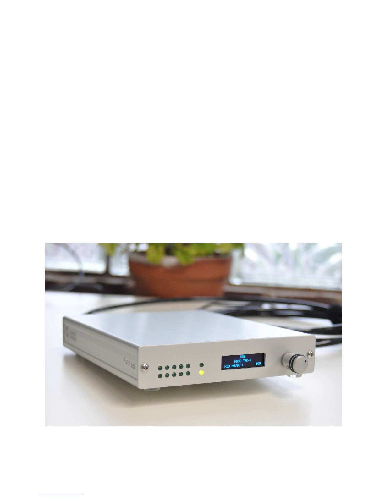
What the isplay shows -
all 3 lines (har ware interface, han hel type, an mo e i entifier/number)
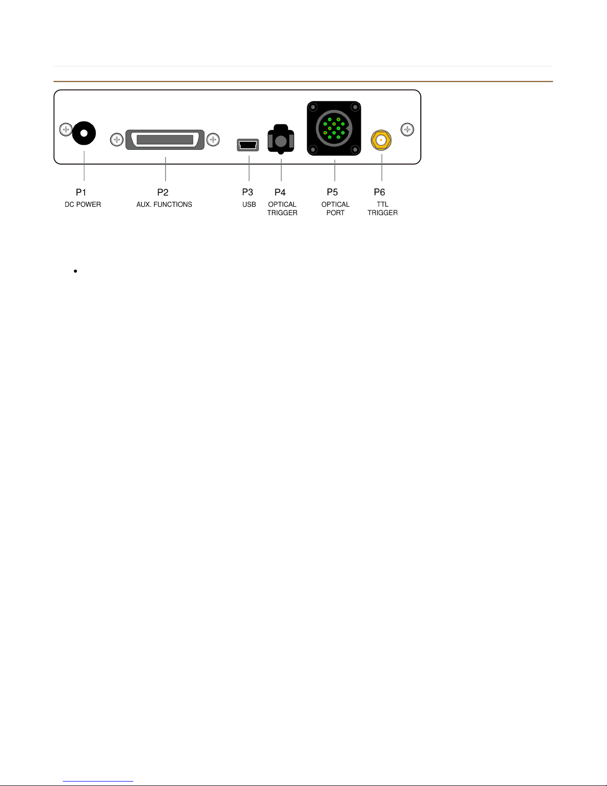
How the han hel evice is connecte -
is it plugge irectly into the interface, or through a removable bun le?
was it connecte before power was applie to the interface unit?
What stimulus presentation/response program you are using, if any.
Here are a few basic things to check:
1.1 Was the han hel evice connecte prior to the 932 being turne on?
important: The interface "looks for" the han hel evice at power-up an sets some parameters base on what is
connecte .
If no han hel evice is connecte at power-up, an then the evice is connecte afterwar s, it will probably not function
correctly.
try: Connecting the han hel evice (with or without the removable bun le) an cycling the power (unplug the power supply
an then plug it in again).
1.2. Di it power-up correctly?
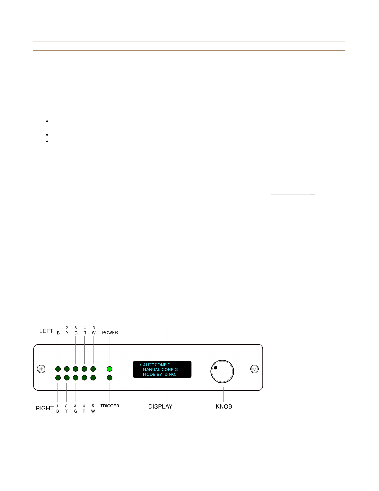
Are the LED in icators blinking properly when buttons on the han hel evice are presse ?
If not, oes the problem persist when the power supply is isconnecte an re-connecte ?
1.3. Are the optical components (the han hel evices an fiber optic bun les) working correctly?
Again, this is usually best etermine by pressing buttons an checking if the LED in icators respon correctly.
1.4 Is the correct han hel evice in icate on the isplay?
The mo el number, which appears on the label on the han hel evice, shoul match what is on the mi le line of the
isplay. For instance, if you using a HHSC-Main.1x4-D button box, the mi le line of the isplay shoul rea ""HHSC-
Main.1x4-D".
In some cases the system will work properly even though the isplay in icates a ifferent han hel evice than the one that
is actually in use. But this mismatch in icates that either the han hel type was manually selecte incorrectly by the user or,
if AUTOCONFIG was use , that the interface incorrectly i entifie the han hel evice.
try: Either manually setting the han hel type or selecting AUTOCONFIG so that the interface unit will interrogate the
han hel evice an try to i entify it.
1.5. Are you getting a reasonable output using a generic program?
The quickest thing to check here is if you get USB output into a program like Notepa . This shoul show simple character
output for any of the mo es which are in icate on the 932 isplay's bottom line starting with "HID KEY ___".
If you are not getting what you expect in your stimulus presentation/response software (Presentation, EPrime, etc) its a goo
i ea to check the output using a more generic program first. If you get correct output here, then getting it to work within
your psychometric program is probably a matter of configuring the program. We may be able to help you configure your
program, but you can probably get better help from the authors of that program.

Switching from FIU-005 systems to 932 systems
If you are already familiar with the FIU-005 (and earlier) interface units these are some of the first differences that might
strike you when you start using the 932.
No more colored LEDs
The 932 has green LEDs for all the buttons rather than colored ones because the 2x5 array of LEDs is used for different
purposes in different modes.
No more BNC trigger input
The TTL trigger input is now on a smaller coaxial connector: its the gold one on the right hand side of the rear panel.
Electrically this input is the same as on the FIU-005 but we needed to use a smaller connector for space reasons.
(Note that there is also an optical trigger on the 932.)
Us ing old button boxes with a new (932) interface
The 932 supports older button boxes in several different ways. Once you've picked one of the following handheld device
types all of the usual button box modes are available and you can pick them from the list just as though you had a newer
HHSC device connected. But the choices handle differing cases:
FIU-005 Handheld T pe
If you manually choose this handheld device type the 932 will operate in a fixed-gain mode very much like the FIU-005 and
its predecessors did. This is the first thing to try if you're trying to use your older handheld devices with the 932. With most
button boxes this choice will "just work" because the optical losses of most button boxes fall within a range that can be
accommodated with a fixed gain.
LEGACY HANDHELD
If you tried to select an FIU-005 handheld device type but one or more of the buttons didn't work correctly you probably
have a combination of button box and bundle optical losses that are too high for the fixed gain of the 932.
In this case you can try selecting LEGACY HANDHELD instead. Now the 932 will use stored gain values for each channel
(button) so it can compensate for a wide range of optical losses on a channel-by-channel basis.
You'll need to calibrate the system for the handheld you intend to use. This is done using the "LEGACY HH CAL" mode
described below.
At the end of the calibration process you'll have the option to save the gain values which will then be applied any time the
LEGACY HANDHELD choice is made. (So you don't need to calibrate things every time.)
Us ing LEGACY HH CAL
When this mode is selected the 932 will scan the 8 possible channels of your HH series handheld device and attempt to find
gain values that will make the buttons work reliably.
To indicate this process is under way the 8 left-most LEDs on the front panel are scanned in a counter-clockwise circular
fashion.
While the channels are scanned the buttons on the button box should be pressed and released so that the electronics can
determine what the "off" and "on" optical losses are. We recommend doing this in a kind of rolling/tapping action similar to
the classic finger-tapping on a desktop associated with impatience or nervousness.
As each button's correct gain value is found the corresponding LED is solidly lit. They should all be lit within 30 seconds or so.
At any time the knob can be pressed and the gain values determined so far can be saved. So if you have a 4 button device
connected you will notice that only the lower 4 LEDs go solid; that's normal because there are only 4 after all. But once
those 4 are solid you can go ahead and save these gains (and the upper 4 that are still being sought will just be disabled).
Once you have answered "YES" to "SAVE SETTINGS?" you can go on to select an output mode and you should be 'on the
air'.

It is not necessary to repeat this process unless you change something significant about the device connections.
Us ing new button boxes with an old (FIU-005) interface
This unfortunately will not work at this time. The optical channels on HHSC series devices are normally transmitting rather
than normally blocking light. When a button is pressed the channel changes from passing light to blocking light. This is the
opposite of the way things worked with the earlier HH series of handheld devices. This change was made to facilitate
automatic recognition and automatic gain compensation of the button boxes.
The HH button boxes are still available and we will continue to repair them indefinitely.
Old trackballs joys ticks and cus tom devices
Most of these devices are almost completely compatible with the 932 and can be made to be completely compatible with a
small amount of modification. For instance the trackball just needs to have the button 'polarity' inverted. Please contact us if
you are thinking about having any of these things upgraded to use with the 932.
Table of contents