Current Tools 99 User manual

CURRENT TOOLS • P. O. BOX 17026 GREENVILLE, SC 29606
800.230.5421 or 864-721-4230 • FAX 864-721-4232
www.currenttools.com
Operating, Maintenance, Safety
and Parts Manual
06/2019
This manual is free of charge. All personnel who operate this Cable Feeder should have a copy
of this manual and read and understand its contents. To request a copy, call or write to the
address below. All information, specifications and product designs may change due to design
improvements or updates and are subject to change without notice. Current Tools does not
assume any liability for damages resulting from misuse or incorrect application of its products.
Read and understand this material before
operating or servicing the Cable Feeder. Failure
to understand how to safely operate and service
this unit may result in serious injury or death.
Model 99 Cable Feeder

1
TABLE OF CONTENTS
Safety Alerts ....................................................................................2
Important Safety Information ........................................................3
Specifications.................................................................................. 4
Features............................................................................................5
Transporting/Lifting the Cable Feeder ..........................................6
Set Up............................................................................................7,8
Loading Cable into Cable Feeder............................................. 9-11
Operating Instructions..................................................................12
Operational Notes .........................................................................13
Exploded View – Lower Drive................................................ 14-15
Parts List — Lower Drive........................................................ 16-17
Exploded View — Upper Drive .............................................. 18-20
Parts List – Upper Drive.......................................................... 21-22
Exploded View and Parts List — Final Assembly ......................23
Exploded View – Electrical System .............................................24
Electrical System Diagram ...........................................................25
Exploded View/Parts List – Gear Motor .....................................26

Hazards or unsafe
p
ractices which, if not avoided, COULD result in serious
personal in
j
ur
y
or death
.
W
ARNIN
G
Hazards or unsafe
p
ractices which, if not avoided, COULD result in minor
personal in
j
ur
y
or propert
y
damage
.
CA
UTI
ON
Immediate hazards which, if not avoided, WILL result in serious
p
ersonal
in
j
ur
y
or death
.
DAN
G
E
R
THIS SAFETY SYMBOL is used to call your attention to instructions
that concern your personal safety. It means: ATTENTION! BE AWARE!
THIS IS AN IMPORTANT SAFETY INSTRUCTION!
Read, understand, and follow these safety instructions. Failure to follow
these safety instructions may result in injury or death.
Safety Alert
Symbol
SAFETY ALERTS
2

Do not operate in wet or damp locations. Do not expose to rain.
Do not operate in a hazardous location or near combustible materials.
Keep all body parts, hair, loose clothing, etc. away from rotating parts and
pinch points. Also, stay clear of cable during operation as it approaches
and is fed through the Cable Feeder.
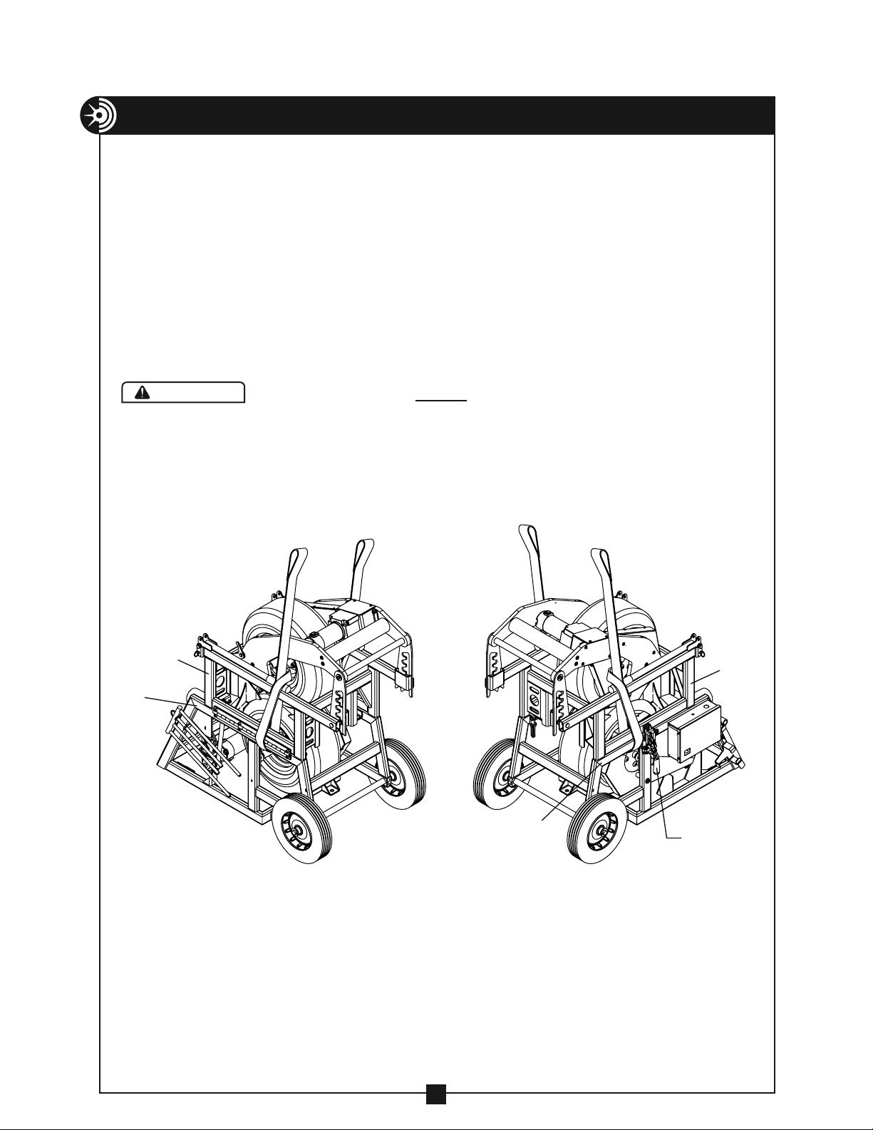
An emergency stop is provided on the Cable Feeder for your safety.
Always inspect before each use to ensure proper operation.
The Cable Feeder has no braking system. Do not use the Cable Feeder to
lift or lower any loads or personnel.
Unplug the Cable Feeder when loading cables to avoid accidental starting.
Upper drive clamp MUST be in closed, locked position before attempting
to lift the Cable Feeder. For instructions on lifting the Cable Feeder, see
Page 6.
Always plug the Cable Feeder into a grounded 115 VAC receptable with a
15 amp GFCI protected circuit. Do not modify the plug provided with the
Cable Feeder. Inspect the power cord before each use.
Unplug the Cable Feeder before servicing or maintenance.
Do not remove guards; they are installed for your protection.
The maximum cable diameter is 3.5". The maximum width of all cables in
the Cable Feeder is 6". Exceeding this width may cause the cables to run
off the tire causing cable damage.
Only use the Cable Feeder for its intended purpose to feed cable off of
cable reels as described in this manual. The Cable Feeder is not to be used
as a cable puller to pull cable or rope through conduit or in cable trays.
Only feed electrical cable through the tires of the Cable Feeder. Do not
allow any sharp objects to contact the tires; doing so may cause damage
to the tires and possibly tire failure.
Inspect the Cable Feeder for damage or wear before each use.
RETAIN SAFETY INFORMATION
3
3
IMPORTANT SAFETY INFORMATION
This manual should be read and understood by all personnel who operate
or service this Cable Feeder. Failure to understand how to safely operate
and service this unit could result in injury or death. This unit should only be
operated and serviced by qualified personnel.
WARNING
DANGER
WARNING
WARNING
WARNING
WARNING
WARNING
WARNING
WARNING
WARNING
WARNING
WARNING
WARNING
WARNING
WARNING
WARNING
DANGER
WARNING
WARNING
WARNING
WARNING
WARNING
WARNING
WARNING
WARNING
WARNING
WARNING
WARNING
WARNING
WARNING
WARNING
DANGER
WARNING
WARNING
WARNING
WARNING
WARNING
WARNING
WARNING
WARNING
WARNING
WARNING
WARNING
WARNING
WARNING
WARNING
DANGER
WARNING
WARNING
WARNING
WARNING
WARNING
WARNING
WARNING
WARNING
WARNING
WARNING
WARNING
WARNING
WARNING
WARNING
DANGER
WARNING
WARNING
WARNING
WARNING
WARNING
WARNING
WARNING
WARNING
WARNING
WARNING
WARNING
WARNING
WARNING
WARNING
DANGER
WARNING
WARNING
WARNING
WARNING
WARNING
WARNING
WARNING
WARNING
WARNING
WARNING
WARNING
WARNING
WARNING
WARNING
DANGER
WARNING
WARNING
WARNING
WARNING
WARNING
WARNING
WARNING
WARNING
WARNING
WARNING
WARNING
WARNING
WARNING
WARNING
DANGER
WARNING
WARNING
WARNING
WARNING
WARNING
WARNING
WARNING
WARNING
WARNING
WARNING
WARNING
WARNING
WARNING
WARNING
DANGER
WARNING
WARNING
WARNING
WARNING
WARNING
WARNING
WARNING
WARNING
WARNING
WARNING
WARNING
WARNING
WARNING
WARNING
DANGER
WARNING
WARNING
WARNING
WARNING
WARNING
WARNING
WARNING
WARNING
WARNING
WARNING
WARNING
WARNING
WARNING
WARNING
DANGER
WARNING
WARNING
WARNING
WARNING
WARNING
WARNING
WARNING
WARNING
WARNING
WARNING
WARNING
WARNING
WARNING
WARNING
DANGER
WARNING
WARNING
WARNING
WARNING
WARNING
WARNING
WARNING
WARNING
WARNING
WARNING
WARNING
WARNING
WARNING
CAUTION
CAUTION

SPECIFICATIONS
• Weight: 345 lbs.
• Dimensions: 26" wide X 42" long X 43" tall
• Power requirements: 115VAC, 15 amps, 60 Hz
• Feeding speed: 0 ft./minute to 36 ft./minute
• Cable Capacity:
8 X 250 MCM Cable
6 X 500 MCM Cable
5 X 750 MCM Cable
Cable size — .25" to 3.5" dia. max.
Maximum Width of all cables 6"
• Maximum Pulling Force:
Single Cable – Approximately 250 lbs.
All Cables – Approximately 1,000 lbs.
• Maximum Reel capacity – 25,000 lbs.
• Tire Pressure – 50 PSI
4
SPECIFICATIONS

5
FEATURES
• Hinged upper drive to allow for easy side loading.
• High grip tires can accommodate no lube or regular cable
• Dual drive motors for maximum grip on cables
• Cable separator guides cables to ensure positive grip on tires
• Heavy duty third wheel caster with quick release mechanism
• Adjustable speed control
• May be operated with remote pendant or optional foot switch
• Low voltage hand control pendant with 8' cable and
magnet for easy storage
• Ratcheting tension adjustment provides tension on cable from
1/4" to 3 1/2" diameter
• Self-lubricating drive chain reduces maintenance
LOWER DRIVE
T-BAR
RECEIVER
2" RIGID OR
IMC CONDUIT
(PROVIDED BY END USER)
T
-ADAPTER
REMOVEABLE
CABLE SEPARATOR
ENTRY SIDE
TRANSPORT
CASTER RELEASE
LEVER
TRANSPORT CASTER
UPPER DRIVE
TENSION
ADJUSTMENT ARMS
T
ENSION
ADJUSTMENT
HANDLE
EMERGENCY
STOP SWIT
CH
UPPER DRIVE CLAMP
TRANSPORT
HANDLES
EXIT SIDE
ANCHOR BRACKET
ADJUSTABLE
SPEED
CONTROL
(4 PROVIDED)
UPPER DRIVE ARMS

6
TRANSPORTING THE CABLE FEEDER
TO ROLL ON A SMOOTH SURFACE:
Rotate both transport handles and pin into position with the detent
pins provided. Next, lift the Cable Feeder by the handles and the
transport caster will rotate into place. To retract the caster, lift up on
the transport handles and push the transport caster release lever with
your foot. This will allow the caster to rotate out of the way. Next,
lower the Cable Feeder.
LIFTING THE FEEDER
When lifting the Cable Feeder, attach sling so that it loops around the
drive frame as shown below.
Upper drive clamp MUST be in closed, locked position
before attempting to lift the Cable Feeder.
WARNING
DANGER
WARNING
WARNING
WARNING
WARNING
WARNING
WARNING
WARNING
WARNING
WARNING
WARNING
WARNING
WARNING
WARNING
UPPER
DRIVE
FRAME
LOWE
R
DRIVE
FRAME
LOWER
DRIVE
FRAME
UPPER
DRIVE
CLAMP
UPPER
DRIVE
FRAME

7
SET-UP
The following will help with setting up the Cable Feeder and cable reels:
• Make sure there is enough room for the cable to remain slack after
the cable exits the Cable Feeder.
• The maximum angle that the cable should approach the Cable
Feeder is 25° from the center line.
• Make sure the cable insulation will not be damaged.
• The cable may pay off from either the top or bottom of the reel.
• Place the ground cable in the farthest slot to the left of the cable
separator as it enters the cable feeder.
25° MAXIMUM
FROM CENTERLINE
AS CABLE
APPR
OACHES FEEDER
PROVIDE SUFFICIENT
DISTANCE HERE FOR
CABLE TO REMAIN SLACK
T-ADAPTER
T-BAR RECEIVER

SET-UP continued . . .
To secure the Cable Feeder:
Using T-Bar
• The Cable Feeder may be secured by using the T-Bar method. Slide
a section of 2" Rigid or IMC conduit into the T-Bar receiver located
at the entry side of the Cable Feeder. Next, slide the other end of the
conduit into the T-adapter. Next, slide a second 2" section of Rigid or
IMC conduit through the T-adapter. Now the Cable Feeder and T-bar
set-up are ready to be positioned against cable reel stands.
Note: The second section of conduit should be long enough to
contact both cable reel stands.
Note: Another method of securing the Cable Feeder may be
needed if the cable is not on the reels. Place the T-Bar
against a stake(s) in the ground, step, etc.
Using Anchors
• Secure the Cable Feeder by anchoring through the four anchor
brackets located on the bottom of the Cable Feeder. Use 3/8" or 1/2"
anchors (provided by end-user).
Always ensure that the structure you are anchoring to
will support the forces generated by the pull, plus a 4:1
safety factor.
WARNING
DANGER
WARNING
WARNING
WARNING
WARNING
WARNING
WARNING
WARNING
WARNING
WARNING
WARNING
WARNING
WARNING
WARNING
CABLE REEL STAND
T-ADAPTER
T-BAR
RECEIVER
STEPS
2 INCH RIGID OR IMC CONDUIT
(PROVIDED BY END USER)
T-ADAPTER
2 INCH RIGID
OR IMC CONDUIT
(PROVIDED BY END USER)
T-BAR
RECEIVER
2 INCH RIGID
OR IMC CONDUIT
(PROVIDED BY END USER)
2 INCH RIGID OR IMC CONDUIT
(PROVIDED BY END USER)
CABLE REEL STAND
T-ADAPTER
T-BAR
RECEIVER
STEPS
2 INCH RIGID OR IMC CONDUIT
(PROVIDED BY END USER)
T-ADAPTER
2 INCH RIGID
OR IMC CONDUIT
(PROVIDED BY END USER)
T-BAR
RECEIVER
2 INCH RIGID
OR IMC CONDUIT
(PROVIDED BY END USER)
2 INCH RIGID OR IMC CONDUIT
(PROVIDED BY END USER)
8

9
LOADING CABLE INTO THE CABLE FEEDER
1. Standing at the exit end of the Cable Feeder, push down and turn the
tension adjustment handle to release the tension adjustment arms
from the ratchet studs. Lift up on the handle and place the tension
adjustment arms with the resting slots (see Figure 1 below) on top of
the ratchet studs.
TENSION
ADJUSTMENT ARM
RATCHET
STUD
TENSION
ADJUSTMENT HANDLE
TENSION
ADJUSTMENT ARM
Lifting tension adjustment
arms to place resting slots on
top of ratchet studs.
Resting slots shown on
top of ratchet studs.
Tension Adjustment
Arm Resting Slot
Figure 1

2. Next, release the upper drive clamp and raise the upper drive.
Note: The upper drive clamp has a safety lock which must be released
to operate the clamp. See photo below.
LOADING CABLE INTO THE FEEDER continued . . .
THUMB SCRE
W
Cable separator shown installed Cable separator shown in storage slots
3. Place the cables over the lower
tire, being sure not to cross the
cables.
Note: Pull safety lock as shown
to release upper drive clamp
10
4. If needed, remove the cable separator from the storage slots and
install as shown below. Be sure to tighten the thumb screw to
secure the cable separator.

11
LOADING CABLE INTO THE FEEDER continued . . .
5. Next, close and reclamp the upper drive
To release latch, lift the lever
on latch as shown.
6. Using the tension adjustment
handle, lower the tension
adjustment arms. Push down
on the handle with enough
pressure to engage one set of
the ratcheting slots onto the
ratchet studs.
Upper drive arms raised
and shown latched into
open position
7. Now you are ready to feed cable.
Note: If needed, the upper drive can be raised and will latch into open
position as shown below.

12
OPERATING INSTRUCTIONS
1. Before operation, be sure the pendant ON/OFF switch is in the OFF
position.
2. Next, plug the Cable Feeder into an 115 VAC, 15 amp, GFCI protected
power source.
3. Adjust the speed control to 12 o'clock position.
4. Turn the circuit break switch located on the side of the Cable Feeder
electrical box to the ON position.
Operate the Cable Feeder by one of the following methods:
• For continuous run: Place the pendant on/off switch in the
“continuous on” position.
• For intermittent operation: With the pendant continuous on/off
switch in the OFF position, depress the pendant jog button.
• If equipped with optional foot switch: Plug the foot switch into the
foot switch outlet located on the front of the electrical box on the
Cable Feeder and depress the foot switch.
5. Adjust the speed by rotating the speed control knob as follows:
1. Clockwise – to increase speed
2. Counterclockwise – to decrease speed
Note: The Cable Feeder is equipped with an emergency stop switch
located on the top of the electrical box on the Cable Feeder. To
activate, push down. To reset, turn clockwise.

13
OPERATIONAL NOTES
• Before feeding begins, make sure the cable on the entry side of the cable feeder
(between the cable reels and the cable feeder) is NOT slack.
• The cable on the exit side of the Cable Feeder should REMAIN SLACK DURING THE
ENTIRE PULL. Do not allow this cable to become taut.
• Keep the speed control at a low setting at the start of the pull.
• Use the speed control to adjust the rate of cable feed to equal that of the cable
puller. Proper use of the speed control should prevent the operator from having to
turn the Cable Feeder off and on during the feeding operation.
• When feeding a cable with a smaller diameter (such as a ground cable) than the
other cables being fed, the smaller cable may tend to feed at a faster rate. To
remedy this:
• Stop the Feeder, then push down and turn the tension adjustment handle to
release the tension adjustment arms from the ratchet studs. Then raise the
upper drive arms. (See photo on the bottom of Page 11).
• Pull back the excess small cable that has built up at the exit end of the
Cable Feeder.
• Lower the upper drive arms and push down on the tension adjustment handle
until the tension adjustment arms engage the ratchet studs.
• Restart the pull.
• If slippage is a problem, more separation may be needed between the ground cable
and the larger cables. Simply place the ground cable in the farthest slot to the left of
the cable separator and skip a slot between the ground cable and the larger cable.
• If necessary, more than one cable may be placed in a single slot of the Cable Separator.
• If the cable feeding off the reels approaches the Cable Feeder at too steep of an angle,
the Cable Feeder may tend to lift. To avoid, move the Cable Feeder further away from
the reel(s) or anchor the Cable Feeder by using the (4) four anchor brackets located on
the bottom of the Cable Feeder or feed the cable from the bottom of the reel.
1) Before use, make sure each tire is inflated to 50 PSI.
2) Chains and bearings are permanently lubricated and should not require any
additional lubrication.
3) Keep all components clean and free of any debris.
MAINTENANCE
KEEP THIS ANGLE
AS SMALL AS POSSIBLE

refer to PARTS LIST on pages 16 & 17
14
EXPLODED VIEW — LOWER DRIVE
WHEELS AND CASTER
DRIVE MOTOR – LOWER

refer to PARTS LIST on pages 16 & 17
15
EXPLODED VIEW — LOWER DRIVE
DRIVE TIRE ASSEMBLYLOWER DRIVE FRAME

16
PARTS LIST — LOWER DRIVE
ITEM # PART # DESCRIPTION QTY.
1 2-1301-4 NUT — HEX NYLON INSERT (5/16"-18) 2
2 2-1501-4 NUT — HEX NYLON INSERT (3/8-16) 8
3 33-53 SCREW — HEX HEAD CAP GR5 ZINC (3/8–16 x 3/4) 4
4 33-706 WELDMENT — WIRE/FOOT SWITCH HOLDER 1
5 66-56 SCREW — SPADE THUMB 18.8SS (5/16–18 X 3/4) 1
6 77-002D1 SCREW — HEX HEAD CAP GR5 ZINC (5/16–18 x 3/4) 4
7 77-004A SCREW — TC (8-32 x 3/8) 12
8 77-004A SCREW — TC (8-32 x 5/8) 1
9 77-016 COTTER PIN — 3/16" x 1-1/4" LONG 2
10 77-017 WASHER — FLAT 3/4"(SAE) 2
11 77-028 STRAIN RELIEF 1
12 77-028A STRAIN RELIEF 3
13 77-033A SCREW — HEX HEAD SELF DRILL ZINC (#10–32 x
1/2) 2
14 77-036A NUT — HEX (#6–32) 4
15 77-061 SCREW – PAN HEAD SLOT (6-32 3/8) 6
16 77-063 SWITCH GUARD 1
17 77-508 PRECUT WIRE LEADS (NOT SHOWN) 1
18 88-47 CIRCUIT BREAKER SWITCH 1
19 99-10 CASTER 1
20 99-100 PROPORTIONAL CONTROLLER 1
21 99-101 BRIDGE RECTIFIER 1
22 99-102 STAND OFF — NYLON 4
23 99-117 OUTLET — FOOT SWITCH 1
24 99-120 KNOB — SPEED CONTROL 1
25 99-18 BEARING — FLANGE, PLAIN 3/4" 2
26 99-2 GEAR MOTOR 1
27 99-21 18.5" x 8.50" TIRE, 99 1
28 99-24 KEY — 3/16 x 3/16 x 1" PLAIN 1
29 99-30 SCREW — HEX HEAD CAP GR5 ZINC (7/16–14 x 1) 4
30 99-31 WASHER — LOCK MEDIUM 7/16" ZINC 4
31 99-32 SCREW — BUTTON HEAD SOCKET (1/2–13 x 3/4) 4
32 99-33 NUT — LUG (1/2"–20) 4
33 99-34 STUD - WHEEL 1/2"–20 4
34 99-38 SCREW — HEX HEAD CAPGR5 ZINC (5/16–18 x 1.5) 5
35 99-5 WHEEL 2
36 99-53 DRIVE CHAIN 1
37 99-85 MASTER LINK 1
38 99-92 E-STOP LEGEND PLATE 1
39 99-93 E-STOP 1
40 99-94 SPEED CONTROL 1
41 99-98 TRANSFORMER 1

17
PARTS LIST — LOWER DRIVE — CONTINUED
ITEM # PART # DESCRIPTION QTY.
42 99-99 SOLID STATE RELAY 1
43 99-545 AXLE 2
44 99-694 BOTTOM FRAME WELDMENT – 99 FEEDER 1
45 99-696 BOTTOM AXLE WELDMENT 1
46 99-715 SPROCKET – DRIVEN, FEEDER 1
47 99-727 ELECTRICAL PLATE — FEEDER 1
48 99-729 TOP — ELECTRICAL BOX — FEEDER 1
49 99-730 PLATE FAB – CASTER, FEEDER 1
50 99-740 LOWER CHAIN GUARD (TOP) 1
51 99-741 LOWER CHAIN GUARD (BOTTOM) 1
52 99-744 GUIDE PLATE WELDMENT 2
53 99-744A GUIDE PLATE WELDMENT 2
54 99-756 SPROCKET — REDUCER 1
55 99-790 CASTER LOCK WELDMENT 1
56 450-20 SPACER, ELEC. BOX 3
57 453-16A NUT — HEX (#8–32) 1
58 524-11 3/8-16 x 1" HEX HEAD CAP SCREW 9
59 528-2 SCREW — HEX HEAD CAP GR5 ZINC (3/8–16 x 2) 1
60 610-25 NUT — HEX NYLON INSERT (3/8–16) 6
61 9518SR-12 NUT — HEX NYLON (1/4–20) 3
62 9544-21 WASHER — FLAT 5/16" USS ZINC 8
63 99-105 DECAL 1
64 77-050 GUARD - PENDANT 1
65 77-451 GASKET 1
66 77-051 SWITCH - FORWARD / REVERSE 1
67 77-052 SWITCH - JOG 1
68 77-048 CONDULET - 1/2" 1
69 77-065 FISH PAPER 1
70 77-3-1A PLUG - PLASTIC 1
71 99-115 CORD (16/3-8’) - PENDANT 2
72 33-45 FOOT SWITCH 1
73 747-39 LOCKWASHER, EXT. TOOTH - #8 1
74 451-22 SCREW, PAN HEAD PHILLIPS, 10-32 x 3/8" 1
75 747-19 MAGNET - ROUND 1
76 747-34 NUT, HEX - THIN NYLON INSERT #10-32 1
77 747-40 LOCK WASHER, INT. TOOTH – 15/32" 2
78 77-072 SCREW - #8-32 x 1/2" RD. HD. PHILLIPS 2

refer to PARTS LIST on pages 21 & 22
18
EXPLODED VIEW — UPPER DRIVE
DRIVE TIRE ASSEMBLY UPPER DRIVE FRAME

refer to PARTS LIST on pages 21 & 22
19
EXPLODED VIEW — UPPER DRIVE
DRIVE MOTOR AND ARMS
Table of contents