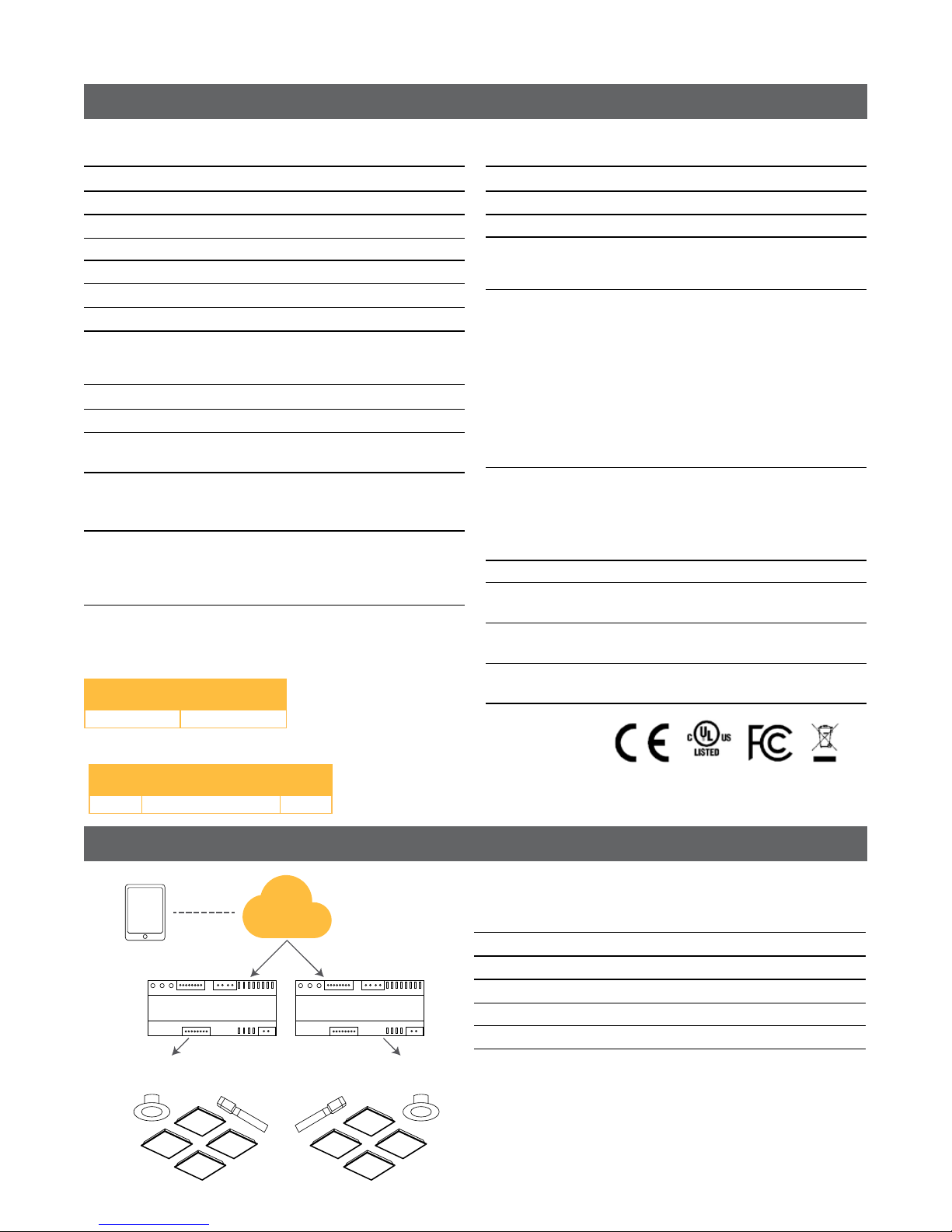
Lightsweep™Digital Controller
Lightsweep™Digital System
BEFORE YOU BEGIN
Read these instructions completely and carefully.
Save these instructions for future use.
Risk of electrical shock. Disconnect power before service
installation, or maintenance of the product.
Installation Guide
CTRL020
IMPORTANT
To ensure the product warranty is valid, please ensure
all installation instructions and environmental conditions
for storage and operation are complied with.
Only GE trained contractors can install the product.
Must be installed in a Cabinet.
Risk of fire. Follow all relevant IEC or UL instructions and
local building codes. Use only IEC or UL approved wire for
input/output connections.
WARNING
WARNING
Seperation of Circuits. Install in accordance with National
Electric Code and local codes rules.
WARNING
Risk of injury. Wear safety glasses and gloves during
installation and servicing.
CAUTION
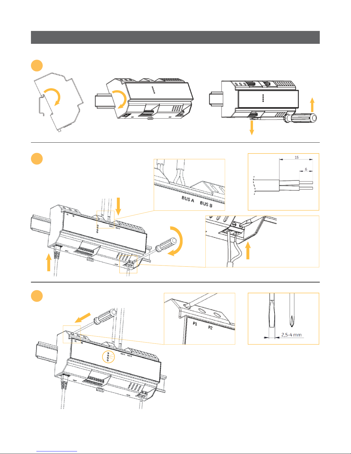
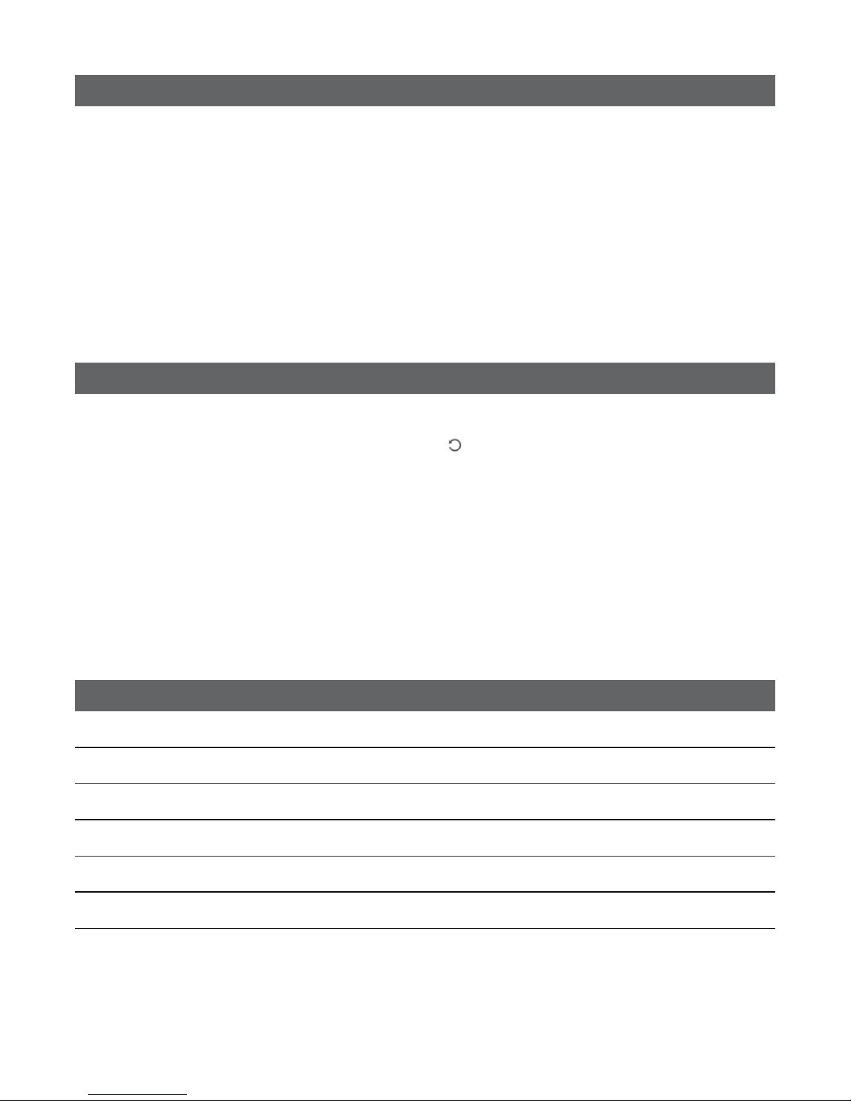
Prepare Electrical Wiring
Electrical Requirements
The Lightsweep™ Digital Controller must be
connected to the mains supply according to its
ratings on the product label.
Grounding Instructions
The grounding and bonding of the overall system
shall be done in accordance with National Electric
Code (NEC) Article 600 and local codes.
BG-
HR-Hrvatska verzija priručnika za ugradnju i sigurnosnih informacija nalazi se na sljedećoj
lokaciji:
CS- Návod k montáži a bezpečnostní informace v češtině najdete zde:
DA-Den danske version af installationsvejledningen og sikkerhedsoplysninger kan ndes på
følgende placering:
NL- De Nederlandse versie van de installatie-instructies en veiligheidsinformatie kan op de
volgende locatie worden gevonden:
ET- Eestikeelse paigaldusjuhendi ja ohutusnõuded leiate aadressilt:
EN-The English version of the installation instruction and safety information can be found at
the following location:
FI-
Asennusohjeiden ja turvallisuustietojen suomenkielinen versio löytyy seuraavasta paikasta:
FR- La version française des instructions d’installation et informations de sécurité est
disponible à l’adresse suivante :
DE- Die deutsche Version der Installationsanleitung und Sicherheitsinformationen nden Sie
in folgendem Verzeichnis:
EL-
HU-A telepítési útmutató és a biztonsági információk magyar nyelvű változata az alábbi
címen található:
IT- La versione italiana del manuale di installazione e sicurezza può essere reperita nella
seguente sezione:
LV- Uzstādīšanas instrukciju un drošības informāciju latviešu valodā var atrast šeit:
LT- Lietuvišką diegimo instrukcijos ir saugos informacijos versiją galima rasti šioje vietoje:
PL- Polską wersję instrukcji instalacji oraz informacje dotyczące bezpieczeństwa można
znaleźć w następującej lokalizacji:
PT- A versão em Português das instruções de instalação e das informações de segurança
pode ser encontrada na seguinte localização:
RO-Versiunea în limba română a instrucţiunilor de instalare şi a informaţiilor de siguranţă
pot găsite la:
SK- Slovenskú verziu montážnej príručky a bezpečnostných inštrukcií nájdete na nasledu
júcej lokalite:
SL-
Slovenska različica navodil za namestitev in varnostnih navodil se nahaja na naslednji strani:
ES- La versión española de las instrucciones de instalación y la información sobre seguridad
puede encontrarse en la siguiente ubicación:
SV- Ni hittar den svenska versionen av installationsanvisningarna och säkerhetsinformationen
på följande plats:
Българската версия на инструкциите за инсталация и информация за
безопасност могат да бъдат намерени на следния адрес:
Μπορείτε να βρείτε την ελληνική εκδοχή των οδηγιών εγκατάστασης και των
πληροφοριών ασφάλειας στην εξής τοποθεσία:
Българската версия на инструкциите за инсталация и информация за
безопасност могат да бъдат намерени на следния адрес:
Μπορείτε να βρείτε την ελληνική εκδοχή των οδηγιών εγκατάστασης και των
π
ληροφοριών ασφάλειας στην εξής τοποθεσία: