Curtis Dyna-Fog Golden Eagle 2610E Installation and operating instructions

Manual Addendum
For
Golden Eagle
The following pages attached in this addendum should be
used instead of the manual when referring to components on
Golden Eagle™.
TM

NOTE
The method used for starting the engine will vary slightly depending on previous conditions of
the machine. Regardless of which of the following conditions exist, the ignition switch must be
depressed to restart the engine.
DRY START: (Applies when the machine is first placed in service; when the machine has been
allowed to run completely out of fuel; or, when the machine has not been in recent use). hen
starting from the dry condition (all fuel drained, consumed or evaporated from the carburetor),
additional actuation of the priming pump will be required to move fuel from the tank to the primer
bulb.
COLD START: (Applies after the engine has been started initially; has been stopped before
running out of fuel; and has been allowed to cool). Under these conditions, very little actuation of the
priming pump is required, as some fuel will usually remain in the carburetor. One actuation of the
priming pump is usually sufficient under these conditions.
HOT START: (Applies after the engine has been started initially; has been stopped before
running out of fuel, and has not been allowed to cool before restarting). Under these conditions,
actuating the priming pump is not usually required as some fuel will usually remain in the
antechamber.
FLOODED START: (Applies after too much fuel has reached the antechamber by excessive
operation of the priming pump). See section on STARTING A FLOODED ENGINE.
FIGURE 1
8

STARTING THE ENGINE
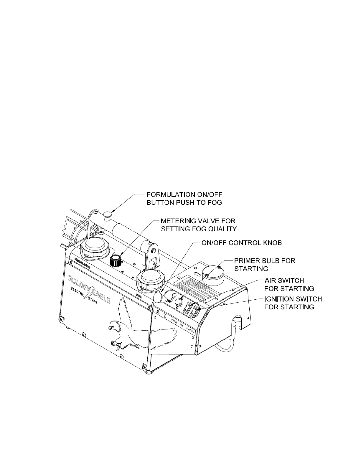
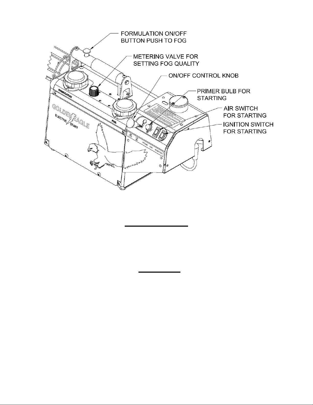
1. Verify that the FORMULATION ON/OFF button is released and that the
FORMULATION METERING VALVE has been rotated fully clockwise (CW) until the
Stop is reached.
.
2. Lift the ON/OFF Control and place it in the "ON" position.
WARNING
DO NOT LEAVE THE MACHINE UNATTENDED WITH THE ON/OFF CONTROL
IN THE ON POSITION, ESPECIALLY IF THE MACHINE HAS BEEN RUNNING.
IF THE ENGINE IS HOT AND THE ON-OFF CONTROL IS IN THE ON
POSITION, THE MACHINE MAY SELF START.
3. Press and hold the Ignition Switch and listen for the audible buzzing or clicking sound of the
Electronic Ignition firing the Spark Plug.
4. Depress and release the "Primer Bulb" repeatedly until the fuel is visible in the Bulb. Once fuel
reaches the Bulb. depress and release the Bulb (3) times for a "cold engine", (1) time for restarting a "hot
engine". (See Page 8 for starting conditions.)
CAUTION
Excessively depressing the primer bulb will flood the engine.
WARNING
FLOODING MAY RESULT IN A LOUD EXPLOSIVE SOUND AND CAUSE
SOME SMALL AMOUNT OF FLAME TO BE EMITTED FROM THE DISCHARGE
(EXHAUST) END OF THE ENGINE.
CAUTION
If flame emits from the discharge (exhaust) end of the engine tube, the engine
is flooded. STOP. See the section STARTING A FLOODED ENGINE.
5. Simultaneously press and hold the Ignition and Air Switches until the Engine begins to start.
6. Once the Engine starts, release the Air Switch and continue depressing the Ignition Switch, until
the Engine runs smoothly.
If the Engine has not started within approximately 40 seconds, repeat steps 4, 5, 6.
If the Engine does not start, and the sound of the Electronic Ignition is not heard, release the
IGNITION SWITCH and proceed to the TROUBLE SHOOTING section of this manual.
WARNING
DO NOT ACTUATE GASOLINE PRIMER BULB WITH ON/OFF CONTROL
KNOB IN OFF POSITION. DO NOT ATTEMPT TO START MACHINE WITH THE
CARBURETOR COVER REMOVED.
NOTE
“Flooded'' means that the fuel-air mixture around the spark plug has become
too rich (too much fuel/or the amount of air available) to ignite.
9

5. After setting the fog quality, the fog may be started and stopped by pressing and releasing the
FORMULAT ON ON-0FF BUTTON.
STOP FOGG NG
1. When fogging is complete, release the FORMULATION ON-OFF UTTON and rotate the
FORMULATION METERING VALVE clockwise (CW) until the stop is reached.
2. Stop the engine by lifting the ON-OFF CONTROL and placing it in the OFF position.
CLEAN UP
1. Drain any unused Formulation from the tank into its original container for proper storage.
CAUT ON
Store all formulations where they are not accessible to children or other
persons who may not be aware of potential dangers involved.
Do not store formulations in unmarked or otherwise improper containers.
Do not store formulations in empty food or beverage containers or in
any container marked for another substance.
Do not re-use empty formulation containers for other purposes. Dispose
of empty formulation containers in accordance with the formulation
label instructions.
2.
After properly storing the formulation, perform the "AFTER EACH USE" maintenance
operations under the MAINTENANCE section of this manual.
17

2. Continue rotating the tool in the same direction and pull back and remove the brush from the tube.
NOTE
It is not normally necessary to push and pull hard on the brush handle;
however, if the engine tube is not cleaned regularly, it becomes
increasingly difficult to clean. Push and pull gently and continue rotating.
Loose carbon will be removed from the tube when the engine is next started.
AFTER EVERY EIGHT (8) HOURS OPERATION
Clean the Formulation Filter
1. Remove the FORMUL TION FILTER and clean it with detergent and water.
FIGURE
20

1 2 3 4 5 6
111111
7
8
14 13 12 11 10 9 18
15
16 17
FIGURE 10
34

TANK-SIDE VIEW OF MACHINE
REF. CURTIS
NO. PART NO. DESCRIPTION
FIGURE 16
1 58522 Formulation Tank Ay.
C58522 Formulation Tank
A10105 Standpipe Connector
A58523 Formulation Standpipe
A85748 El ow,⅛ MPT -¼T
G195463 Nut, ¼ Tu e
G114628 Sleeve, ¼ Tu e
A21120 Union El ow
A21081-1 Plug, ⅛ NPT-Male
2 N58565 Line Ay., Formulation Tank/Check Valve
A58212-3 Tu e
A58239 Insert, Brass ¼ Tu e
G145463 Nut,¼ Tu e
G114628 Sleeve,¼ Tu e
A743123-3 Spring, Anticrimp
3 N58564 Line Ay., Formulation Tank/Metering Valve
A58212-4 Tu e
A58239 Insert, Brass ¼ Tu e
G145463 Nut, ¼ Tu e
G114628 Sleeve, ¼ Tu e
4 C58254 Fuel Tank and Bar Ay.
5 N58608-1 Fuel Line Ay.
58713-2 Tu ing, Tygon, .250, 5.38”
80296-12 Clamp, hose, D25, Dou le Wire
58316 Filter, 3/16 X 60 Microns
58713-3 Tu ing, Tygon, .250 OD
6 N58605 Line Ay., Check Valve/Tee
A58212-1 Tu e
A58239 Insert, Brass ¼ Tu e
G145463 Nut, ¼ Tu e
G114628 Sleeve, ¼ Tu e
7 A58609 Switch, N.O., Rocker
8 N58615 Screw, 6-32 x ½ CRPH
9 A58534 Primer Blu Ay.
A63428 Primer Blu
A58711-1 Tu e, Vinyl (7.0” long)
A58711-2 Tu e, Vinyl (6.5” long)
10 B58272-4 Control Kno Ay.
45

Table of contents
Other Curtis Dyna-Fog Fog Machine manuals