Curtis Dyna-Fog 2505 Use and care manual


INDEX
Page
Number
Specifications ………………………………………………………………… 3
Operating Principle …………………………………………………………. 3
Major Components Diagram ………………………………………………. 4
Placement of the Light Trap ……………………………………………….. 5
Operating the Light Trap …………………………………………………… 5
Battery Holder………………………………………………………………… 6
Recommended Light Bulb …………………………………………………. 6
Troubleshooting Tips ………………………………………………………. 7
Optional Sealed Lead Acid Battery ………………………………………. 7
Exploded Isometric (Parts diagram) ……………………………………… 8
Parts List ……………………………………………………………………. 9
Optional Air Gate……………………………………………………………. 10
Optional CO2 (Gas) kit …………………………………………………….. 10
Optional CO2 (Dry Ice) kit …………………………………………………. 10
Other Light Traps …………………………………………………………… 10
- Page 2 -

Specifications
Power Supply……………………………………………………………… 6 volts DC
Current Draw………………………………………………………….. 300 ma (nom.)
Motor Speed………………………………………………………………. 2500 RPM
Fan …………………………………………………………… 3 In. (7.6 cm)/4 blades
Light Bulb………………………………………………................ # 44, # 47 0r # 503
Weight of Light Trap………………………………………………… 1.55 lbs. (.70 kg)
Weight of Battery Holder and extension wire assembly…………… .5 Lb (.22 Kg)
Weight of optional 12 AH/6V Battery Assembly ………………... 4.75 Lb (2.16 Kg)
Weight of optional 110 AC/6VDC Battery Charger …………..… 0.95 Lb (0.43 Kg)
Shipping Weight ………………………………… ( 1) unit/carton = 4.0 Lb (1.82 kg)
Shipping Dimensions:
one unit/carton = 15.5” (39.4cm) x15.5” (39.4cm) x 6.6” (16.8 cm)
Outer pack, Six units/carton = 16” (40.6 cm) x 16” (40.6 cm) x 44” (111.7 cm)
Operating Principle
Modern pest management requires surveillance data in order to plan control
work. Field surveys are the foundation of an effective program. Data on the
mosquitoes with the greatest potential to adversely affect public health and
comfort, including data on mosquito density and distribution, are essential in
order to plan and conduct effective control measures.
Light traps are an easy, relatively low cost way to obtain an index of the number
of mosquitoes in an area. This light trap was designed to be an efficient means
for collecting samples of adult mosquitoes. Once collected, the mosquitoes can
then be identified and counted to provide a statistical representation of the
population density and type of species in any given area. Collecting a sample of
mosquitoes using this light trap can provide invaluable information necessary for
evaluation and control of the mosquito population.
Once analyzed, this information can be used to:
•Accurately determine the best times and areas to spray using “Curtis
Dyna-Fog” type aerosol sprayers or foggers;
•Provide information oh how well the spray pattern is penetrating target
areas
•Identify disease carrying species and the potential for vector born
diseases in the area
•Determine species resistance to different insecticides
•Evaluate the effectiveness of a spraying program
With the addition of carbon dioxide as an attractant in the form of dry ice, the
CDC trap becomes a powerful surveillance tool. The CO, baited CDC trap
samples a wider range of mosquito species and increases the numbers of
mosquitoes captured.
DYNA-FOG CDC UV MOSQUITO LIGHT TRAP MODEL 2505
- Page 3 -


Placement of the Light Trap
For the Light Trap to operate effectively it must be placed in the proper location.
In general, best results will be achieved if the trap is placed in areas of higher
humidity. These areas will usually have more foliage and cover. Also, locating
the trap a few yards into the edge of woods and near marshes, swamps and
streams yield excellent results.
Select a remote location (at least 50 feet away from any structures if possible).
Avoid placing a trap near any other light sources or open fields as they may
detract from its effectiveness. The height at which the trap is suspended can
influence the species composition of the collection. Normally, traps are hung 5-6
ft off the ground. This height is satisfactory for the majority of species
encountered in routine. (Note: If it is important that the collected mosquitoes
remain alive, care should be taken to avoid placing the trap where it will be in
direct sunlight.)
The number of traps needed for an area depends upon the amount of accuracy
desired. The more traps that are placed, the greater the statistical accuracy.
Typically, several traps will be located in known areas of activity. If the location
does not produce the expected number of mosquitoes, relocate the trap. Field
trials show that relocating traps distances of only 25 feet (7.62 m) can
significantly change the amount of mosquitoes collected.
NOTE: FOLLOW THE SPECIFIC INSTRUCTION FROM THE
SCIENTIFIC/TECHNICAL PERSONNEL IN YOUR VECTOR CONTROL
PROGRAM AND/OR MOSQUITO CONTROL DISTRICT.
Operating the Light Trap
NOTE: To yield the most accurate results, the trap should be operated for five
consecutive nights.
When connected the light trap to a 6 volt DC power source, the trap will begin
operating fan and light. Both fan and light will remain ON until disconnected from
power source (or the batteries charge is drained), regardless of the day light or
darkness of the environment around.
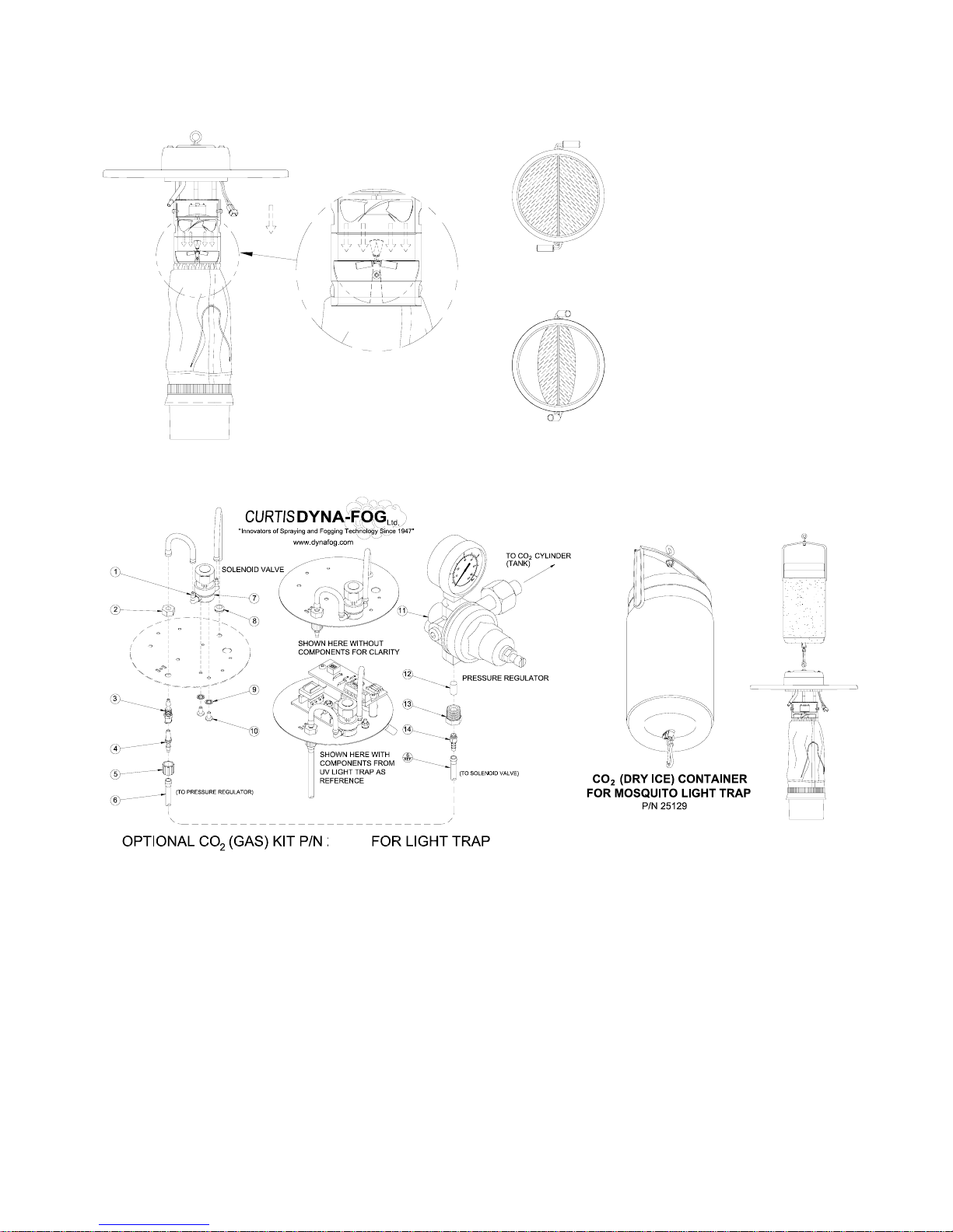
Past experience has shown that using a pheromone such as Octenol and/or placing a 2”
(5.08 cm) cube of dry ice in an ice bucket suspended directly above the trap will increase
the number of mosquitoes collected. Also, collection peak periods fluctuate on a 4 week
cycle with the light and dark phases of the moon.
Field trials have shown that the best collection times are during the dark phases of the
moon and on overcast nights.
The Light trap model 2505 requires 300 ma (nominal) to operate at 6.0-6.3 volts
DC. The trap is designed to be powered by a nominal voltage of 6 volts DC.
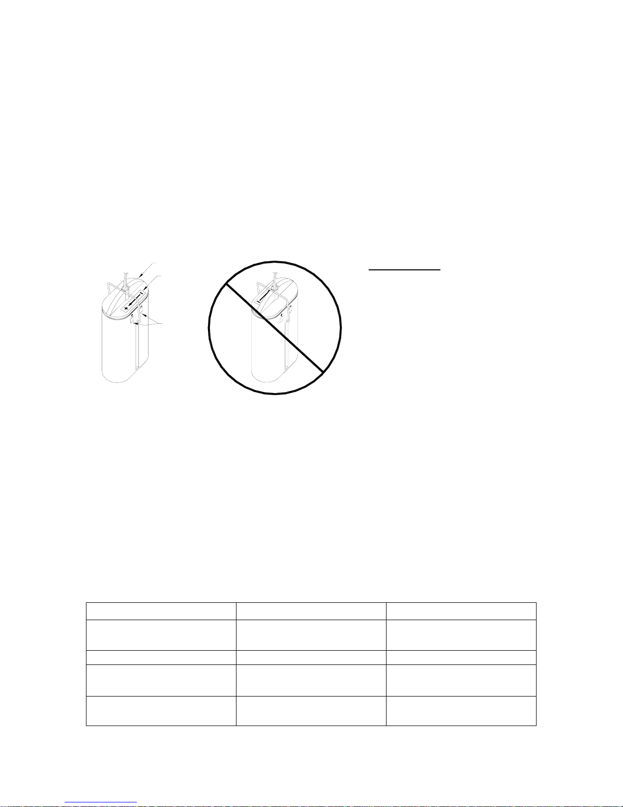
This may be in the form of 4 “D” size alkaline batteries which will allow operation
of the trap for temporary periods of time which will vary depending on the light
bulb used before the batteries will need to be replaced. If 4 “D” size batteries are
used, is recommended to make daily collection of the samples taken for the trap,
and make any required maintenance to the batteries, if required. Another power
- Page 5 -

source that can be used is a rechargeable 6 volt battery such as a sealed lead
acid which will give extended operation depending on the capacity rating (usually
expressed in amp hours) of the battery used, before it will need to be recharged.
The maximum run time for a fully-charged and new battery can be estimated by
dividing the Amp-Hr rating of the battery by the current consumption of the trap.
See in this manual the section related to the optional Dyna-Fog 6 V DC Sealed
Lead Acid Battery.
Be sure to observe that the batteries are installed and connected with the proper
polarity to assure proper operation and prevent damage to the trap.
As DC current is unidirectional, wire leads are coded: the ribbed wire goes to the
(+) and the smooth wire goes to the (-) polarity. The plastic housing of the
connectors are also coded, side of the tab goes to the (+) polarity.
Recommended Light Bulb types are:
Bulb Type Voltage Current MSCP
# 503 5.1 Volts 150 ma .6
# 47 6.3 Volts 150 ma .5
# 44 6.3 Volts 250 ma .9
MSCP = Mean Spherical Candlepower. Higher MSCP means brighter light.
The Light Trap model 2505 is supplied with the Light Bulb # 44.
Troubleshooting Tips
Problem Possible Cause Corrective Action
Unit will not operate Battery wires connected
backwards at battery Check wires at battery
Weak battery Recharge Battery
Poor wiring connections Ensure all wiring
connections are tight
Lamp doesn’t work Burnt out Lamp or Lamp
is loose If necessary, replace with
Lamp specified
IMPORTANT
See the ICONS on top of the
battery case for installing
batteries in proper direction.
When installing battery lid,
orient it so that (+) LABEL is
on the same side as the (+)
symbol of the ICON molded in
the case.
Orienting the lid in the wrong
direction will prevent the unit
from operating properly.
- Page 6 -
CORRECT LID INCORRECT LID
LID
LABEL
ICON

Technical Details of Dyna-Fog 6 V DC Sealed Lead Acid Batteries
Sealed Construction - SLA batteries unique construction and sealing technique guarantee
that no electrolyte leakage can occur from the terminals or case of any battery. This feature
insures safe, efficient operation of SLA battery in any position.
Electrolyte Suspension System - All SLA batteries utilize an electrolyte suspension system
consisting of a glass fiber separator material. This suspension system allows maximum life
and service.
Gas Generation - Batteries have a unique design that effectively controls generation of gas
and allows recombination within the battery over 99% of gas generated during normal usage.
Maintenance Free Operation - During the expected five years float service life of SLA
batteries, there is no need to check the specific gravity of the electrolyte, or add water. In
fact, there is no provision for these maintenance functions.
Low Pressure Venting System - SLA batteries are equipped with a safe, low pressure
venting system, which operates at 7 psi to 10 psi, designed to release excess gas and reseal
automatically in the event that gas pressure rises to a level above the normal rate.
Cyclic Service Life - Depending upon the average depth of discharge, over 1,000
discharge/ recharge cycles can be expected from batteries
Low Self Discharge - At room temperature, its self-discharge rate of SLA batteries is
approximately 3% of rated capacity per month.
Operating Temperature Range - SLA batteries may be used over a broad range of ambient
temperatures.
Optional Sealed Lead Acid Battery Available – Allows extended operation where traps
cannot be maintained on a daily basis. Contact Curtis Dyna-Fog for more information.
Dyna-Fog offers an optional power source that can be used, a rechargeable 6
volt 12 Amp-Hour battery, which allows longer operation time of the Light trap
between charging periods.
Be sure to observe that the battery is installed and connected with the proper
polarity to assure proper operation and prevent damage to the trap.
- Page 7-
CAUTION
A
s DC current is
unidirectional, wire
leads are coded: the
ribbed wire goes to the
(+) and the smooth wire
goes to the (-) polarity.
The plastic housing of
the connectors are also
coded, the tab goes to
the (+) polarity.
Orienting the wires in
the wrong direction will
prevent the unit from
operating properly.
COLOR FOR
FOR NEGATIVE SIDE
AREA IN RED
POSITIVE SIDE
COLOR FOR
POSITIVE SIDE
SYMBOL (+) FOR NEGATIVE SIDE
BLACK SLEEVE
NEGATIVE SIDE
SYMBOL (-) FOR
IDENTIFY
TAB TO
POSITIVE SIDE
RIBBED WIRE FOR
POSITIVE SIDE
ASSEMBLY
BATTERY
OPTIONAL
AREA IN BLACK


OTHER DYNA-FOG LIGHT TRAPS
P/N MODEL DESCRIPTION
25200 2502 COMMERCIAL W/BATTERY HOLDER
25200-1 2501 COMMERCIAL W/LOCAL BATTERY HOLDER
25086 2500 CDC MINIATURE (W/KILLING JAR)
25086-2 2504 CDC MINIATURE, BRIGHT LIGHT, W/SWITCH
25086-3 2503 CDC MINIATURE, UV LAMP, W/SWITHC
25086-4 2505 CDC MINIATURE WITHOUT PCB
A WIDE VARIATY OF OPTIONAL ITEMS ARE AVAILABLE
OPTIONAL SELF CLOSING LIGHT TRAP GATE P/N 25115
Utilizing the optional
self-closing gates promotes
battery conservation and
allows longer time periods of
unattended and uncollected
light trap specimens without
specimen escape.
CURTIS DYNA-FOG self
closing gate can be used on
any light trap, including the
competitors.
After installing self-closing
gate, for trap with electronic
switch, you can set the
function switch to position
number 3 for battery
conservation.
PARTIAL OPEN GATES
Air current during fan
operation opens gate to
force specimens into net.
Gate closes when fan shuts
off trapping specimens into
the net for later collection.
AIRFLOW
CLOSED GATES
(NORMAL OPERATING POSITION)
(FAN IS NOT OPERATING)
- Page 10 -
25140

NOTES
________________________________________________________________________
________________________________________________________________________
________________________________________________________________________
________________________________________________________________________
________________________________________________________________________
________________________________________________________________________
________________________________________________________________________
________________________________________________________________________
________________________________________________________________________
________________________________________________________________________
________________________________________________________________________
________________________________________________________________________
________________________________________________________________________
________________________________________________________________________

PULSE-JET POWERED THERMAL FOGGERS:
From 0-120 GPH (0-453 LPH) output. Our complete line
include different models like the Superhawk, Golden
Eagle, Trailblazer, Patriot, Blackhawk, Mister III, Mister
Max, SilverCloud and Model 1200.
Portable or Truck mounted machines. Different models
are available for Oil base or Water base formulations.
WIND DRIVEN ROTARY ATOMIZERS:
The ASC-A10 is a wind driven atomizer designed for Fixed Wing aircraft. The rotational
speed of the atomizer controls the droplet size and can be adjusted by changing the
angle of the blades. Also available is the ASC-A10H for Rotary Wing application.
No other Rotary atomizer for aircraft can handle the amount of Flow rate as the ASC
Atomizer.
Several accessories are available to meet your requirements. Also available in 12 or 24
VDC, see rotary atomizer above (Model ASC-A20).
COMBUSTION ENGINE DRIVEN ULV AEROSOL
GENERATORS:
Truck mounted Units powered by 8, 9, 11 or 18 HP four cycle,
OHV Gasoline Engine. Diesel version available. One, two or four
nozzles. Optional full remote control of boom functions (rotation of
turntable and angle of nozzles).
Diversity of pumping systems, Gear, Piston and Diaphragm.
Pressurized system available for overseas market.
Optional Radar Syncroflow.
40 cc Two cycle portable machines also available.
DYNA-FOG
®
Offers a complete and wide assortment of aerosol
g
enerator s
y
stems.
CURTIS DYNA-FOG
®
Ltd.
www.dynafog.com
Call or write today for a free brochure
17335 US Highway 31 North
Westfield, IN 46074 U.S.A.
Phone: (317) 896-2561
Fax: (317) 896-3788
Internet: www.dynafog.com
www.dynafog.com
REV. 11-04
L30 L15
ASC-A20
ELECTRIC HAND-HELD ULV/MIST
GENERATORS: Full line of electric cold fog
applicators with 1 Gal (3.8 L) tank, available in
115 and 230 VAC. An Electric Thermal
version is available. For bigger Formulation
capacity, larger tanks are available.
CYCLONE
ULTRA-FLEX HURRICANE
ELECTRIC ROTARY ATOMIZERS:
DYNA-JET L30: State of the Art,
Electric Rotary Atomizer ULV Aerosol
Generator. 12 VDC, Light Weight,
Truck mounted Machine with FMI
pump. Optional Radar Syncroflow.
DYNA-JET L15: Drift Sprayer for
migratory pest control like Locust.
Flow Rate from 0 to 2000 ml/min.
Optional Radar Syncroflow.
ASC-A20: State of the Art, Electric
Rotary Atomizer, for use on Fixed
Wing and Rotary Wing aircraft.
Table of contents