Custom Equipment PS-1030 Programming manual

MAINTENANCE & TROUBLESHOOTING
MANUAL
SUPO-742 | REV A
PS-1030
PS-1430
MOBILE ELEVATING WORK PLATFORM
BY CUSTOM EQUIPMENT LLC

NOTES
Custom Equipment, LLC
General Information
2647 Hwy 175
Richfield, WI 53076
U.S.A.
P: +1-262-644-1300
F: +1-262-644-1320
www.hybridlifts.com
Service Information
P: +1-262-297-5195
Parts Information
P: +1-262-297-5196
MAINTENANCE & TROUBLESHOOTING
PS-1030 | PS-1430
SUPO-742
REV A
2

FOREWORD
Original instructions written in English
The purpose of this Maintenance Manual is to provide qualified service personnel with information for servicing and
maintaining Hy-Brid Lifts. All information in this manual must be read and understood before any attempt is made
to service this machine.
The operation and safety manual is considered a part of the work platform and contains instructions and operating
procedures essential to properly and safely operate the Custom Equipment Hy-Brid Lift. Users must read and
understand all information in the Safety and Operations Manual before operation.
THE OPERATION AND SAFETY MANUAL MUST
BE READ AND UNDERSTOOD PRIOR TO OPERATING THE MACHINE.
• The user/operator should not accept operating responsibility until the manual has been read and understood as
well as having operated the lift under supervision of an experienced and qualified operator.
• Because the manufacturer has no direct control over machine application and operation, proper safety
practices are the responsibility of the user and all operating personnel.
ANY MODIFICATION ON THIS MACHINE WITH
OUT THE EXPRESS WRITTEN CONSENT OF THE MANUFACTURER IS PROHIBITED.
DANGER
WARNING
MAINTENANCE & TROUBLESHOOTING
PS-1030 | PS-1430
SUPO-742
REV A
3

TABLE OF CONTENTS
NOTES.......................................................................................................................................................................................... 2
FOREWORD ................................................................................................................................................................................ 3
TABLE OF CONTENTS............................................................................................................................................................... 4
INDEX OF FIGURES.................................................................................................................................................................... 5
SECTION 1 | SAFETY .................................................................................................................................................................. 6
1.1 | SAFETY SYMBOLS.......................................................................................................................................................................... 6
1.2 | GENERAL RULES AND PRECAUTIONS .................................................................................................................................. 6
1.3 | SAFETY GUIDELINES.................................................................................................................................................................... 7
SECTION 2 | MAINTENANCE ................................................................................................................................................... 8
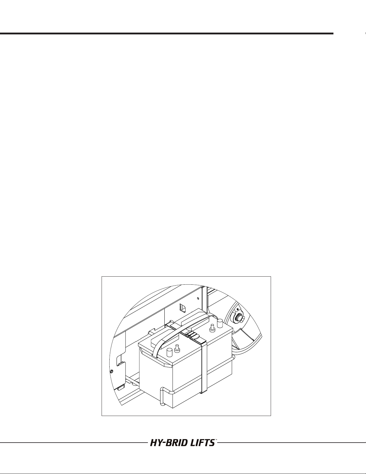
2.1 | BATTERY MAINTENANCE...........................................................................................................................................................8
2.2 | CHARGING THE BATTERY.........................................................................................................................................................8
2.3 | BATTERY MAINTENANCE AGM BATTERIES ........................................................................................................................ 10
2.4 | BATTERY MAINTENANCE WET CELL BATTERIES.............................................................................................................. 10
2.5 | LUBRICATION...............................................................................................................................................................................11
2.6 | COMPONENTS REQUIRING ADJUSTMENT .......................................................................................................................11
2.7 | EXAMINATION, REPAIR, REPLACEMENT OF LIMITED LIFE COMPONENTS ..............................................................11
2.8 | SAFETY DEVICES AND SYSTEMS REQUIRING CHECKS ..................................................................................................11
2.9 | STORAGE .....................................................................................................................................................................................11
2.10 | MAJOR ALTERATIONS OR REPAIRS.....................................................................................................................................11
SECTION 3 | MAINTENANCE CHECKLISTS ......................................................................................................................... 12
3.1 | PRESTART INSPECTION CHECKLIST................................................................................................................................... 14
3.2 | PREDELIVERY/ANNUAL/FREQUENT INSPECTION CHECKLIST.................................................................................. 15
SECTION 4 | TECHNICAL REFERENCES .............................................................................................................................. 16
4.1 | HYDRAULIC SCHEMATIC ......................................................................................................................................................... 16
4.2 | ELECTRICAL SCHEMATIC ....................................................................................................................................................... 18
4.3 | CONTROL BOARD DIAGNOSTIC..........................................................................................................................................20
SECTION 5 | WIRING DIAGRAMS.......................................................................................................................................... 22
5.1 | WIRING DIAGRAM .....................................................................................................................................................................22
5.2 | LWR CTL WIRING DIAGRAM ...................................................................................................................................................24
5.3 | UPPER CONTROLS WIRING DIAGRAM................................................................................................................................26
SECTION 6 | TROUBLESHOOTING FLOWCHARTS ...........................................................................................................28
6.1 | MAIN POWER/SAFETY CIRCUIT.............................................................................................................................................28
6.2 | DRIVE CIRCUIT...........................................................................................................................................................................30
6.3 | ELEVATE CIRCUIT ......................................................................................................................................................................32
6.4 | LOWER CIRCUIT.........................................................................................................................................................................34
6.5 | STEER CIRCUIT...........................................................................................................................................................................36
SECTION 7 | PARTS..................................................................................................................................................................38
SECTION 8 | WARRANTY........................................................................................................................................................40
SECTION 9 | INSPECTION AND REPAIR LOG .....................................................................................................................42
MAINTENANCE & TROUBLESHOOTING
PS-1030 | PS-1430
SUPO-742
REV A
4

INDEX OF FIGURES
REVISION:
REV A:.............................................................................................................................................................................................MAY 2019
FIGURE 1: MAINTENANCE LOCK USE................................................................................................................................................. 7
FIGURE 2: MAINTENANCE LOCK STORAGE ..................................................................................................................................... 7
FIGURE 3: BATTERY CHARGER LIGHT DISPLAY............................................................................................................................... 9
FIGURE 4: BATTERY LOCATION ......................................................................................................................................................... 10
MAINTENANCE & TROUBLESHOOTING
PS-1030 | PS-1430
SUPO-742
REV A
5

FAILURE TO FOLLOW THIS WARNING WILL CAUSE
DEATH OR PERSONAL INJURY.
“DANGER” indicates an imminently hazardous situation,
which, if not avoided, will result in death or serious
injury.
FAILURE TO FOLLOW THIS WARNING MAY CAUSE
DEATH OR PERSONAL INJURY.
“WARNING” indicates a potentially hazardous situation,
which, if not avoided, could result in death or serious
injury
FAILURE TO FOLLOW THIS WARNING MAY CAUSE
INJURY OR DAMAGE TO EQUIPMENT.
“CAUTION” indicates a potentially hazardous situation
which, if not avoided, could result in minor or
moderate injury or damage to equipment
SECTION 1 | SAFETY
1.1 | SAFETY SYMBOLS
1.2 | GENERAL RULES AND PRECAUTIONS
An operator of any type of work platform is subject to certain hazards that cannot be protected by mechanical
means. It is therefore essential that operators be competent, careful, physically and mentally fit and thoroughly
trained in safe operation of this machine.
Although Custom Equipment, LLC conforms to specified ANSI & OSHA requirements, it is the responsibility of the
owner to instruct operators with the safety requirements made not only by Custom Equipment, LLC, but by the
various safety boards in your area, as well as additional requirements set forth by ANSI and OSHA. If you come
across a situation that you think might be unsafe, stop the platform and request further information from qualified
sources before proceeding.
MAINTENANCE INFORMATION IS FOR USE BY TRAINED PERSONNEL ONLY
NEVER REACH BETWEEN SCISSORS LINKS OR PROP UP PLATFORM
UNLESS MAINTENANCE PINS ARE IN PLACE
DANGER
CAUTION
WARNING
WARNING
WARNING
MAINTENANCE & TROUBLESHOOTING
PS-1030 | PS-1430
SUPO-742
REV A
6

SECTION 1 | SAFETY
1.3 | SAFETY GUIDELINES
Maintenance Lock
The maintenance lock must be placed into position whenever the machine is being serviced in the raised or partially
raised position. Serious injury and/or death could result if maintenance lock is not used properly.
FIGURE 1: Maintenance Lock Use FIGURE 2: Maintenance Lock Storage
FAILURE TO COMPLY WITH THE LISTED SAFETY PRECAUTIONS MAY RESULT IN MACHINE DAMAGE,
PERSONNEL INJURY, OR DEATH.
Other Guidelines
• Never work under an elevated platform until maintenance locks have been engaged.
• Remove all rings, watches, and jewelry when performing any maintenance.
• Do not wear long hair unrestrained or loose fitting clothing and neckties which may become caught on or
entangled in equipment.
• Observe and obey all warnings and cautions on machine and in manual.
• Keep oil, grease, water, etc. wiped from standing surfaces and handholds.
• Before making any adjustments, lubricating or performing any other maintenance, shut o all power controls.
• Battery should always be disconnected during replacement of electrical components.
• Keep all support equipment and attachments stowed in their proper place.
• Use only approved nonflammable cleaning solvents.
• After maintenance, inspect the machine as described for Pre-delivery.
WARNING
MAINTENANCE & TROUBLESHOOTING
PS-1030 | PS-1430
SUPO-742
REV A
7

SECTION 2 | MAINTENANCE
2.1 | BATTERY MAINTENANCE
This unit is equipped with either deep cycle 12-volt AGM maintenance-free batteries or deep cycle Group 27
batteries.
Batteries should be fully charged after each use. Opportunity charging can be done but the batteries should be fully
charged at least every other day if they are used daily. Charge in a ventilated area as gases may be released through
the pressure relief valve if the batteries are excessively over-charged.
NOTE: The surrounding temperature greatly aects the power reserve within a battery.
EXAMPLE: A battery that is 100% charged at 80°F (27°C) drops to 65% at 32°F (0°C). At 0°F (-18°C), this battery will
drop to 40% eciency.
NEVER ADD ACID TO BATTERY!
2.2 | CHARGING THE BATTERY
BATTERIES GENERATE EXPLOSIVE GASES. KEEP SPARKS AND FLAME
AWAY FROM BATTERIES. DO NOT SMOKE WHILE CHARGING.
The charger may include an interlock circuit. If so equipped, the unit will not operate while charging.
Operating while charging will shorten battery life.
To charge:
• Park the machine on a level surface.
• Plug charger into AC outlet until charged.
• For best battery life, leave the charger plugged in until machine will be used again. The charger will maintain the
battery charge.
CAUTION
WARNING
MAINTENANCE & TROUBLESHOOTING
PS-1030 | PS-1430
SUPO-742
REV A
8

Standard Charger Status Lights:
SECTION 2 | MAINTENANCE
DO NOT OPERATE UNIT WHILE
CHARGING. DO NOT DISABLE
CHARGER INTERLOCK.
FIGURE 3: Battery Charger Light Display
WARNING
CHARGE STATUS LIGHT
POWER LIGHT
MEANING Standby Mode
(Or battery
/connection error
Normal Charging:
Bulk Charging
Normal Charging:
Absorption Stage
Charge Complete:
Flat/Maintenance Mode
Charger Error
MAINTENANCE & TROUBLESHOOTING
PS-1030 | PS-1430
SUPO-742
REV A
9

SECTION 2 | MAINTENANCE
2.3 | BATTERY MAINTENANCE AGM BATTERIES
Battery cycle life will vary significantly depending on the depth of discharge. The deeper the depth of discharge the
fewer cycles a battery will deliver. Conversely, the shallower the depth of discharge the more cycles a battery will
deliver. To optimize the health of your battery, limit discharge to 80%.
The performance and life of a battery will vary with application, usage, temperature and depth of discharge. AGM
batteries tend to deliver higher than their rated capacity (up to 10-15% higher) for -30 cycles until they are “broken in”
and settle at their rated capacity.
Operating batteries above 80°F (27°C) will yield runtimes above the rated capacity and operating batteries below
80°F will yield runtimes below the rated capacity. Cold temperatures can significantly reduce battery capacity.
Although higher temperatures increase the battery capacity they also accelerate corrosion and reduce overall battery
life.
2.4 | BATTERY MAINTENANCE WET CELL BATTERIES
If this unit is equipped with deep cycle 12-volt Group 27 batteries, the care and maintenance of your battery has
much to do with how well this unit functions. Battery wiring and water level should be checked monthly. Do not
overfill. When the cells are too full, fluid will seep out when charging. The solution is at its proper strength when
the battery is manufactured. Use distilled water and keep fluid up to proper level. When required, water should be
added to battery after charging, unless water level is below the plates.
• Remove side cover to access battery.
• Remove battery caps and check fluid level.
• Fill each cell (if needed) to split ring with distilled water.
• Reinstall caps.
• Wash all dirt, debris, acid, etc., o battery whenever corrosion is detected. Use a solution of 5ml baking soda per
0.95 liters of warm water.
• Coat terminals with a commercially available coating.
• Close cabinet and latch in place.
M
FIGURE 4: Battery Location
MAINTENANCE & TROUBLESHOOTING
PS-1030 | PS-1430
SUPO-742
REV A
10

2.5 | LUBRICATION
Item Specification Frequency of Lubrication
Wheels Teflon Spray Quarterly
2.6 | COMPONENTS REQUIRING ADJUSTMENT
Under normal use, no components should require adjustment. Contact the manufacturer if adjustments are
required.
2.7 | EXAMINATION, REPAIR, REPLACEMENT OF LIMITED LIFE COMPONENTS
With proper use, regular battery charging, and regular inspection, there are no limited life components that require
routine replacement.
2.8 | SAFETY DEVICES AND SYSTEMS REQUIRING CHECKS
Check safety functions as part of daily inspection. Check that the brakes are holding.
2.9 | STORAGE
After periods of storage, exposure to extremes of ambient conditions-heat, cold, moisture, dust etc. inspect
the machine. Batteries will need to be charged. Refer to the Pre-Delivery/Frequent Inspection Checklist in the
Maintenance Manual.
2.10 | MAJOR ALTERATIONS OR REPAIRS
Any alterations must be approved by the manufacturer. Major repairs, which aect the stability, strength, or
performance of the machine must also be approved by the manufacturer, recorded, and include machine
inspection and testing. Never attach pipe racks, material lifting devices, or make any other alteration that is not part
of the intended design of the machine.
SECTION 2 | MAINTENANCE
MAINTENANCE & TROUBLESHOOTING
PS-1030 | PS-1430
SUPO-742
REV A
11

SECTION 3 | MAINTENANCE CHECKLISTS
Regular inspection and conscientious maintenance is important to ecient economical operation of this machine.
It will help to assure that equipment will perform satisfactorily with a minimum of service and repair. Make checks at
the stated intervals or more frequently if required by local operating conditions. The following inspection checklists
are included in this manual:
• Pre-Start (required before operation at each work shift)
• Pre-Delivery/Frequent/Annual (Required every 3 months, after periods of storage, and after any alterations or
repairs)
The rated life of the machine is Light Intermittent Duty (typical use 10 years, 40 weeks per year, 20 hours per week,
5 load cycles per hour).
FAILURE TO PERFORM INSPECTIONS AND PREVENTATIVE MAINTENANCE AT
RECOMMENDED INTERVALS MAY RESULT IN THE UNIT BEING OPERATED WITH A
DEFECT THAT MAY RESULT IN INJURY OR DEATH OF THE OPERATOR.
CAUTION
MAINTENANCE & TROUBLESHOOTING
PS-1030 | PS-1430
SUPO-742
REV A
12

THIS PAGE WAS INTENTIONALLY LEFT BLANK
MAINTENANCE & TROUBLESHOOTING
PS-1030 | PS-1430
SUPO-742
REV A
13

SECTION 3 | MAINTENANCE CHECKLISTS
3.1 | PRESTART INSPECTION CHECKLIST
Y-Yes/Acceptable N-No/Unacceptable R-Repaired N/A - Not equipped with this feature Y N R N/A
VISUAL INSPECTIONS
There are no loose or missing parts. □ □ □ □
Check that warning and instructional labels are legible and secure. Ensure that load capacity is clearly marked. □ □ □ □
Check the platform rails and safety gate for damage. □ □ □ □
Platform and base controls are not missing, damaged, or disconnected. □ □ □ □
Electrical cables and wires are not torn, frayed, or disconnected. □ □ □ □
Hydraulic hoses are not torn or loose, and there are no leaks. Hoses and the cables have no worn areas or
chafing. □ □ □ □
Check the tires for damage. Check that wheel axle retaining rings and any set screw(s) in rear wheel are tight. □ □ □ □
Check that all snap rings are secure in grooves on pivot pins. □ □ □ □
FUNCTIONAL TESTS
Gate closes automatically and latches. □ □ □ □
Platform Controls: Check all switches and push buttons for proper operation.
Emergency Stop (Stops all movement) □ □ □ □
Enable Switch (Does not elevate unless enable is pressed) □ □ □ □
Joystick (Return to neutral, drives forward & reverse,)
Enable Trigger (Must be activated for joystick-operated movement)
Thumb rocker steers right & left
□
□
□
□
□
□
□
□
□
□
□
□
If so equipped, horn sounds when button is pressed. □ □ □ □
Base Controls: Check all switches and push buttons for proper operation.
Emergency Stop (Stops all movement) □ □ □ □
Key Switch (Selects Platform Control, Ground Control, or O) □ □ □ □
Up/Down Rocker Switch (Elevates, Lowers) □ □ □ □
Descent Alarm (Not damaged, sounds for descent; may also sound for drive & elevate, if so equipped) □ □ □ □
Tilt Alarm (Not damaged, sounds when tilted and machine elevated above designated height) □ □ □ □
Master Power Switch disconnects battery □ □ □ □
Wheels: Front and rear wheels rotate freely. □ □ □ □
Drives in slow speed when elevated. □ □ □ □
Brakes: Machine stops when joystick released. □ □ □ □
Pothole guards deploy and lock when platform is elevated. □ □ □ □
Lift does not elevate when pothole guards are blocked. □ □ □ □
Date: Inspected by:
Model: Serial Number:
• Keep inspection records up-to-date.
• Record and report all discrepancies to your supervisor.
• A dirty machine cannot be properly inspected.
THIS CHECKLIST MUST BE USED AT THE BEGINNING OF EACH SHIFT OR
AFTER EVERY SIX TO EIGHT HOURS OF USE. FAILURE TO DO SO COULD
AFFECT THE SAFETY OF THE OPERATOR.
CAUTION
Pre-start Inspection (Pro Series Models)
MAINTENANCE & TROUBLESHOOTING
PS-1030 | PS-1430
SUPO-742
REV A
14

Model: Serial Number:
• Check each item listed below.
• Use proper operating, service, and maintenance manual for specific information and settings
• If an item is found to be unacceptable make the necessary repairs and check the “repaired” box.
• When all items are “acceptable”, the unit is ready for service.
• If an item is found to be unacceptable, make the necessary repairs and check the “repaired” box. When all
items are “acceptable,” the unit is ready for service.
Y — Yes/Acceptable N — No/Unacceptable R — Repaired N/A — Not equipped with this feature
WORK PLATFORMS SHALL BE INSPECTED, SERVICED, AND ADJUSTED TO
MANUFACTURER’S REQUIREMENTS BY A QUALIFIED MECHANIC PRIOR TO
EACH SALE, LEASE, OR RENTAL, AND EVERY 3 MONTHS OR 150 HOURS,
WHICHEVER COMES FIRST, AND ANNUALLY.
CAUTION
Y N R N/A Y N R N/A
Base: Rails/Extending platform:
Inspect slide tracks for damage
□ □ □ □
Extends freely
□ □ □ □
All frame bolts tight
□ □ □ □
Cables in place/secure
□ □ □ □
Pump secure
□ □ □ □
Locks in stowed position
□ □ □ □
DC motors secure
□ □ □ □
Locks in extended position
□ □ □ □
Batteries fully charged
□ □ □ □
Functions:
For PS Series models:
Tie rods secure
□ □ □ □
All functions (Drive,Elevate,Steer) operational
(see Pre-Start Inspection for details)
□ □ □ □
Wheels: Pothole guards deploy when platform elevated
□ □ □ □
Snap rings secure
□ □ □ □
Emergency stop breaks circuits
□ □ □ □
Bolts/nuts tight
□ □ □ □
Slow speed limit switch set properly
□ □ □ □
All shields/guards in place
□ □ □ □
Pothole interlock functions correctly
□ □ □ □
Scissors: Brakes: Operational
□ □ □ □
No broken welds
□ □ □ □
Emergency Down operational
□ □ □ □
No bent beam members
□ □ □ □
Wiring:
All rollers turn freely
□ □ □ □
Switches secure
□ □ □ □
Ret. rings secure on pivots
□ □ □ □
Contactor(s) secure
□ □ □ □
Maintenance locks:
Stored in designated location
□ □ □ □
Tight on terminals (No loose wiring)
□ □ □ □
Platform: Oil: Level 1” from top (when platform stowed)
□ □ □ □
No bent rails
□ □ □ □
Check all hose for leaks
□ □ □ □
No broken welds
□ □ □ □
Check all fittings for leaks
□ □ □ □
All rails in place/secure
□ □ □ □
Battery charger secure/operational
□ □ □ □
110V outlet safe/working (if applicable)
□ □ □ □
Tilt sensor
□ □ □ □
Entrance gate closes freely
□ □ □ □
Warning horn (if applicable)
□ □ □ □
Decals: Hour meter operational
□ □ □ □
Legibile
□ □ □ □
Battery indication operational
□ □ □ □
Correct capacity noted
□ □ □ □
Operator’s Manual is on the unit
□ □ □ □
Proper placement & quantity
□ □ □ □
If equipped with load sensing:
Overload light & alarm sounds when overloaded
□ □ □ □
Date: Inspected by:
SECTION 3 | MAINTENANCE CHECKLISTS
3.2 | PREDELIVERY/ANNUAL/FREQUENT INSPECTION CHECKLIST
MAINTENANCE & TROUBLESHOOTING
PS-1030 | PS-1430
SUPO-742
REV A
15

SECTION 4 | TECHNICAL REFERENCES
3.50 GPM
1
2
0.5-10.0 GPM
C
B
A
A
B
C
D
1
2
3
4
5
6
7
8
8
7
6
5
4
3
2
1
B-SIZE
ORIGINALLY DRAWN BY: DJS
Custom Equipment, Inc.
Richfield, WI 53076
Phone: (262)644-1300
DATE:05/27/2015
HYDR SCH,HBLG
SCALE:1:1
DO NOT SCALE DRAWING
THIS DRAWING IS CONFIDENTIAL AND PROPRIETARY TO CUSTOM EQUIPMENT AND IS LOANED IN EXPECTATION THAT IT WILL BE KEPT CONFIDENTIAL AND USED ONLY FOR THE PURPOSE FOR WHICH IT IS LOANED.
SPEC/MATL: Schematic
DRAWING #: HS-HB
REV
DESCRIPTION OF CHANGE
DATE
REV BY
A
ECO #
SHEET 1 OF 2
WEIGHT: APPROX. 0.00 LB.
A
4.1 | HYDRAULIC SCHEMATIC
Part No. HS-HB
MAINTENANCE & TROUBLESHOOTING
PS-1030 | PS-1430
SUPO-742
REV A
16

3.50 GPM
1
2
0.5-10.0 GPM
C
B
A
A
B
C
D
1
2
3
4
5
6
7
8
8
7
6
5
4
3
2
1
B-SIZE
ORIGINALLY DRAWN BY: DJS
Custom Equipment, Inc.
Richfield, WI 53076
Phone: (262)644-1300
DATE:05/27/2015
HYDR SCH,HBLG
SCALE:1:1
DO NOT SCALE DRAWING
THIS DRAWING IS CONFIDENTIAL AND PROPRIETARY TO CUSTOM EQUIPMENT AND IS LOANED IN EXPECTATION THAT IT WILL BE KEPT CONFIDENTIAL AND USED ONLY FOR THE PURPOSE FOR WHICH IT IS LOANED.
SPEC/MATL: Schematic
DRAWING #: HS-HB
REV
DESCRIPTION OF CHANGE
DATE
REV BY
A
ECO #
SHEET 1 OF 2
WEIGHT: APPROX. 0.00 LB.
A
SECTION 4 | TECHNICAL REFERENCES
MAINTENANCE & TROUBLESHOOTING
PS-1030 | PS-1430
SUPO-742
REV A
17

SECTION 4 | TECHNICAL REFERENCES
-
+
M
M
M
TS-100
B+
B-
M1+
M1- M2-
M2+
P15-7
P15-10 P15-12
P15-9
P15-14P15-13
P15-8
P15-6 P15-5
P15-15
P15-3
P15-11
P15-4
P15-2 P15-1
P9-9
P9-8
P9-6
P9-7 P9-5
P9-3 P9-4
P9-2 P9-1
P12-12 P12-11P12-10
P12-9
P12-8
P12-7
P12-6
P12-4 P12-5
P12-3P12-2 P12-1
V
1
2
43
+
-
1K
1W
NO
-
+
M
87
87A
85 30
R1
86 87
87A
86 30
R2
85
87A
R3
30
85
86
87
87
87A
85
86
R4
30
NO
NC
CONFIG
SHOWN:
PH LS1
A-3 A-2 A-6 A-5
A-13 A-14
A-8
A-12 A-15
A-1
NO
NO
A-11
A-9
A-4
A-10
A-7
B-9
B-3
B-2
B-12
B-7
B-10
B-1
B-8 B-6
B-11
OFF
OFF
B-4 B-5
C-3
C-7
C-8
C-9 C-6 C-2 C-5
C-4
C-1
NC
H-1
J-5
NC
NO
J-14
H-2
K-4
K-8
K-7
K-3
K-2
K-9
K-6
K-1
J-6
J-7
J-2
J-1
J-3
J-4
J-13
J-8
H-3
J-12
J-11
H-5
H-8
H-7
D-1
D-3
D-2
T-4
T-5
T-1
T-2 T-3
T-6
T-7
T-8
H-6
BUTT-1
1 2
20A
NC
+
-
+
-
OFF
NO
SIG
-
+
AS1
(OPTIONAL FLASHING BEACON)
C
B
A
A
B
C
D
1
2
3
4
5
6
7
8
8
7
6
5
4
3
2
1
B-SIZE
ORIGINALLY DRAWN BY:
Custom Equipment, Inc.
Richfield, WI 53076
Phone: (262)644-1300
DATE:
ELEC SCH,HBLG S4
SCALE:1:1
DO NOT SCALE DRAWING
THIS DRAWING IS CONFIDENTIAL AND PROPRIETARY TO CUSTOM, EQUIPMENT AND IS LOANED IN EXPECTATION THAT IT WILL BE KEPT CONFIDENTIAL AND USED ONLY FOR THE PURPOSE FOR WHICH IT IS LOANED.
SPEC/MATL: Schematic
DRAWING #: WS-112-20-401-50
REV
DESCRIPTION OF CHANGE
DATE
REV BY
B
Revise Hydraulic Pump Ground Connection
05/29/2019
GLH
ECO #
2019-3296
SHEET 1 OF 1
WEIGHT: APPROX. 0.00 LB.
B
4.2 | ELECTRICAL SCHEMATIC
Part No. WS-112-20-401-50
MAINTENANCE & TROUBLESHOOTING
PS-1030 | PS-1430
SUPO-742
REV A
18

SECTION 4 | TECHNICAL REFERENCES
-
+
M
M
M
TS-100
B+
B-
M1+
M1- M2-
M2+
P15-7
P15-10 P15-12
P15-9
P15-14P15-13
P15-8
P15-6 P15-5
P15-15
P15-3
P15-11
P15-4
P15-2 P15-1
P9-9
P9-8
P9-6
P9-7 P9-5
P9-3 P9-4
P9-2 P9-1
P12-12 P12-11P12-10
P12-9
P12-8
P12-7
P12-6
P12-4 P12-5
P12-3P12-2 P12-1
V
1
2
43
+
-
1K
1W
NO
-
+
M
87
87A
85 30
R1
86 87
87A
86 30
R2
85
87A
R3
30
85
86
87
87
87A
85
86
R4
30
NO
NC
CONFIG
SHOWN:
PH LS1
A-3 A-2 A-6 A-5
A-13 A-14
A-8
A-12 A-15
A-1
NO
NO
A-11
A-9
A-4
A-10
A-7
B-9
B-3
B-2
B-12
B-7
B-10
B-1
B-8 B-6
B-11
OFF
OFF
B-4 B-5
C-3
C-7
C-8
C-9 C-6 C-2 C-5
C-4
C-1
NC
H-1
J-5
NC
NO
J-14
H-2
K-4
K-8
K-7
K-3
K-2
K-9
K-6
K-1
J-6
J-7
J-2
J-1
J-3
J-4
J-13
J-8
H-3
J-12
J-11
H-5
H-8
H-7
D-1
D-3
D-2
T-4
T-5
T-1
T-2 T-3
T-6
T-7
T-8
H-6
BUTT-1
1 2
20A
NC
+
-
+
-
OFF
NO
SIG
-
+
AS1
(OPTIONAL FLASHING BEACON)
C
B
A
A
B
C
D
1
2
3
4
5
6
7
8
8
7
6
5
4
3
2
1
B-SIZE
ORIGINALLY DRAWN BY:
Custom Equipment, Inc.
Richfield, WI 53076
Phone: (262)644-1300
DATE:
ELEC SCH,HBLG S4
SCALE:1:1
DO NOT SCALE DRAWING
THIS DRAWING IS CONFIDENTIAL AND PROPRIETARY TO CUSTOM, EQUIPMENT AND IS LOANED IN EXPECTATION THAT IT WILL BE KEPT CONFIDENTIAL AND USED ONLY FOR THE PURPOSE FOR WHICH IT IS LOANED.
SPEC/MATL: Schematic
DRAWING #: WS-112-20-401-50
REV
DESCRIPTION OF CHANGE
DATE
REV BY
B
Revise Hydraulic Pump Ground Connection
05/29/2019
GLH
ECO #
2019-3296
SHEET 1 OF 1
WEIGHT: APPROX. 0.00 LB.
B
MAINTENANCE & TROUBLESHOOTING
PS-1030 | PS-1430
SUPO-742
REV A
19

SECTION 4 | TECHNICAL REFERENCES
4.3 | CONTROL BOARD DIAGNOSTIC
LED Code Possible Cause
Fast Flash Control Module is not calibrated, Do not operate unit.
Steady
Unit has just been powered on. You may need to wait for initialization, then re-select function.
Ready to operate, things should be working normally.
A function is selected but the enable trigger is not squeezed.
1-1 The control module is not calibrated. Do not use this unit.
2-1
The key switch selector switch indicate the mode in which the TS100 must operate. If neither
input is active, or if both are active together, the TS100 does not know how to function.
Check key switch and wiring to P15-1 and P12-1.
2-2
A safety feature is locking functions or a switch has failed.
Check that platform is not overloaded, operating on a level surface, and pothole guards deploy/
Check that joystick is neutral when powered on.
Check that joystick trigger is not closed for too long without selecting a function.
Check for failed joystick, selector switches, and up/down switches.
3-x
There is a problem with the drive contactor or valve wiring, or with the motor power wiring;
disconnect connector P9 to see if the problem is caused by drive contactor or valve wiring (if the
fault clears, check for an illegal B+ supply in to P9)
Check motor power wiring; with the drive contactor open the B+ power terminals should be at
10V-15V (significantly lower than B+) If the LED is steady at power-on, and the fault (3-5) occurs
after a delay when attempting to drive or lift, the motor may be stalled and causing an overload of
the TS100 or there is a power wiring error like connecting the B+ cable to a motor stud
3-2 Check P9 wiring. One or more signals showing outputs when all should be o.
3-3 Check B+ stud connections on controller. Voltage is too high.
3-4 There is voltage on safe pre-valve supply when there should not be.
Controller may need to be replaced.
3-5 The drive brake current is too high.
Motor overload. Check for a siezed motor or for power wiring to motors.
4-x
There is a problem with battery supply, the height and/or pressure sensors, the supply to them, or
the temperature sensor inside the TS100
Check battery supply to EMS inputs P15-1 or P12-1 (relative to the B- stud); the battery supply
should be between 15V and 32V
Check the output from height sensor (P12-12)
If the TS100 heatsink is very hot then perhaps the controller has temporarily shut down – if so,
platform lowering is still allowed; wait for the controller to cool down
4-2 Functions Locked: Board is overheated. Check pump, drive motor wiring.
Problem with controller internal voltage. Controller may need to be replaced.
When using the LED for diagnosis, note that a DUAL
FLASH code is indicated. The LED will flash on/o a
certain number of times, pause o for a short delay, then
flash on/o a second certain number of times, followed
by a much longer pause o. The sequence will then
repeat.
EXAMPLE: The LED flash code 3-2 will look like: on/
o/on/o/on/o-short-delay/on/o/on/o-long-delay/
repeat
MAINTENANCE & TROUBLESHOOTING
PS-1030 | PS-1430
SUPO-742
REV A
20
Other manuals for PS-1030
1
This manual suits for next models
1
Table of contents
Popular Boom Lift manuals by other brands

Terex
Terex Genie Z-135/70 installation instructions

Terex
Terex Genie GTH-3007 Service manual

nifty
nifty Mk 3 Seies Operating/safety instructions

Oshkosh Corporation
Oshkosh Corporation JLG E300AJ Service and maintenance manual

Oshkosh Corporation
Oshkosh Corporation JLG 600SC Operation and safety manual

Terex
Terex Genie Z-34/22 IC Service and repair manual