CustomCrimp HS-150 User manual

1
CustomCrimp HS-150,
HS-300 & HS-500 Hose Saws

Revised 11/4/2015
Coolant Flow Adjust
Air Flow Adjust
2
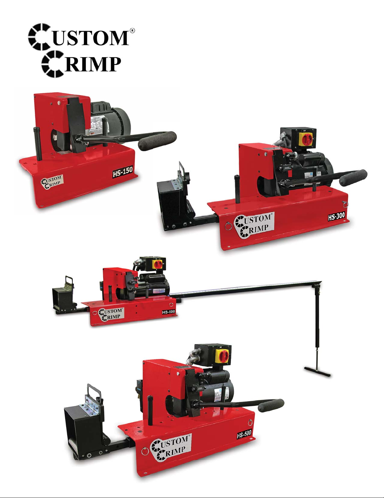
CustomCrimp® HS Models
The HS150 (1 HP) saw is capable of cutting up to 1-1/4 inch 4 wire hose and up to 1 inch 6 wire hose.
The HS300 (3 HP) saw is capable of cutting up to 1-1/4 inch 6 wire or 2 inch 2 wire hose.
The HS500 (5 HP) saw is capable of cutting up to 2 inch 6 wire hose with the serrated blade installed.
Installation
Mount the saw on a sturdy workbench.
The HS150 Hose Saw is only available in 110V single phase confi guration.
For the HS300 and HS500 Saws:
Make certain that the electric service is correct for the saw. The HS 300 and HS 500 saws are available in:
3 HP and 5 HP 220 Volt Single Phase
3 HP and 5 HP 220 Volt 3 Phase
3 HP and 5 HP 480 Volt 3 Phase
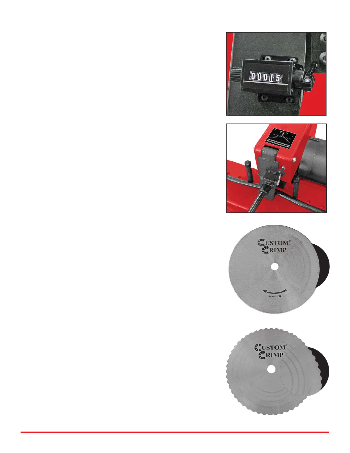
Check the blade rotation. The top of the blade should rotate towards the front of the saw. If
rotation is not correct on a 3 phase saw, reverse any two of the hot wires.
Always wear safety Glasses
Allow the blade to reach full speed before starting a cut
Periodically examine the blade for cracks and/or broken teeth.
Replace if necessary.
Do not remove or defeat any of the guards or safety features of the saw
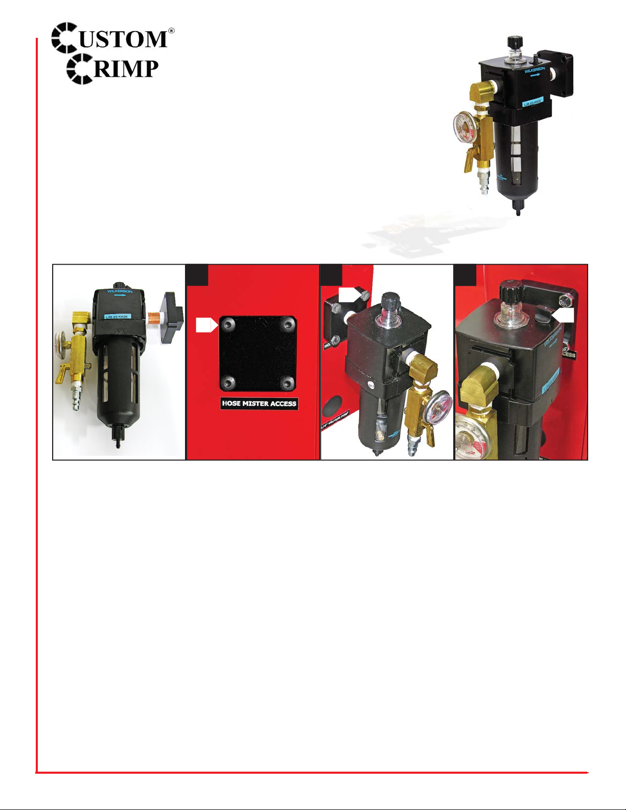
Mister Installation (Optional)
A Mister Kit (P/N 103172) is available for both the
HS 300 and HS 500 Hose Saws. The mister sprays a fi ne mist of
air tool oil on the saw blade for longer blade life and cleaner cuts.
Adjust the air pressure and fl ow control to spray a fi ne mist on the
blade. Addition of a mister kit will give smoother, cleaner cuts and
prolong blade life.
Refer to pages 5 and 6 for installation and setup of the Mister
Kit.
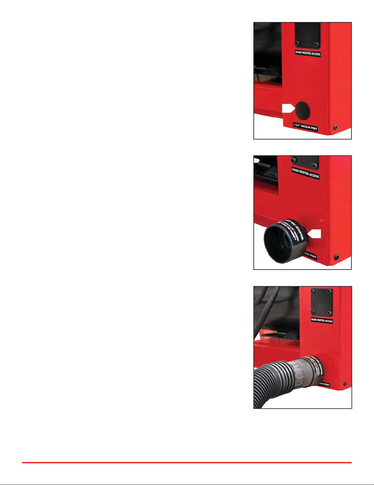
Hose Channel System (Optional)
A Hose Channel System (P/N 103073) is available in 5 foot sections
for the HS300 & HS500 models. The Hose Channel System both
measures and supports the hoses up to 2 inch diameter as they are
being cut.
Hose Helper (Standard on HS300 & HS500)
A “Hose Helper” attachment for the HS300& HS500 prevents the
hose from being drawn back during a cut and gives the operator the
ability to more precisely control the cut length. The “Hose Helper”
can be mounted on either end of the saw.

3
Counter (HS300 & HS500 Models only)
A resetable counter makes it easy to keep track of the number of cuts made.
Hose Bending Pins
Hose Bending Pins prevent the blade from binding during a cut.
Pins should be positioned in the holes in the saw table such that the hose
opens slightly during the cut. Spread the pins further apart for larger
hoses.
The hose should begin to bend before contacting the blade. This will
increase blade life and keep the hose from tearing and deforming.
Apply steady downward pressure on the handle in order to force the hose
into the blade. Do not apply enough force to stall the blade, and ease up
on the pressure before the blade completes the cut. This will keep from
separating the wires as the blade exits the hose.
Blade Choice
Two blades are available. Choose the correct blade for the type of
hose being cut.
Note: New blades must be properly conditioned to assure long
life and clean cuts. For the fi rst ten cuts, feed the blade slowly
through a medium size hose. this will properly break in and
condition the blade for long life.
Double Bevel Blade with SS Slots
The double bevel smooth blade (P/N 104050) is recommended for braided
hose and will give minimal debris in the cut hose.
Scalloped Blade (General Purpose)
The scalloped blade (P/N 104034) is recommended for all spiral hose.
Note: The edges of the blade may appear to be dull. This does not
mean that the blade is not eff ective. As long as the blade is still
giving clean cuts, do not replace the blade.
NOTE: PAY CLOSE ATTENTION TO THE DIRECTION OF
ROTATION MARKED ON THE BLADE. IT IS THE OPPOSITE OF
MOST BLADES OF THIS TYPE.

4
Change Saw Blade
Remove the 5 screws holding the Side cover in place and
remove the side cover.
Remove the 2 No 10-24 screws holding the black Saw
Blade Access Panel in place and remove the insert in
order to provide clearance to remove the blade.
Hold the arbor in place with a wrench and remove the nut
holding the saw blade. There are wrench fl ats on the arbor
behind the blade. (Note that this is a left handed nut).
When replacing a blade, if the blade has a rotation arrow,
make certain that the blade is mounted so that it rotates
in the direction of the arrow.
Replace the Saw Blade Access Panel insert and the Side
Cover.
DO NOT OPERATE THE SAW WITHOUT
ALL OF THE GUARDS IN PLACE

5
Run vacuum during cutting process.
Insert supplied 1 ¼” Vacuum Adaptor (B)
(for 2 ½” shop vac, or vacuum accessories).
Insert Vacuum Adaptor
Optional 1 ¼” Vacuum Port located on rear of hose saw.
NOTE: Do not recommend using at the same time as Mister.
Remove Plastic Plug (A). A
B

6
The following procedures can be used to install the Mister Kit on the HS 300 and HS 500
models of Custom Crimp® Hose Saws.
Remove the HS-300 / HS-500 Mister Kit from its packaging and verify that all components are
properly installed and all fi ttings are securely tightened as shown above, and then follow the
steps below to install the Mister Kit Lubricator.
Step
1
. Unplug hose saw. Remove the bolts and black cover from the Hose Mister Access (A).
Step
2
. Insert the Hose Manifold Mister into the Hose Mister Access, and secure it with the 1/4 - 20
x 3/4” Hex Bolts provided (B).
Step
3
. Remove the Fill Plug located on the top of the Mister Lubricator (C).
123
A
B
C
Full Assembly
P/N: 103172
Installation and Set Up
of the HS-300 / HS-500 Mister Kit

7
Step
4
. Pour 1 bottle of 4 oz of mister oil into the fi ll port (D). Then thread the Fill Plug back in.
2 bottles of 4 oz of mister oil are included, please note reservoir only holds 4 oz (Mister Oil part
number P/N: 104156).
Once the Mister Lubricator has been installed follow the steps below to adjust the air
pressure and oil drops:
4
5
55
D
E
H
I
G
F
6
Step
5
. Make sure hose saw is still unplugged, and remove side panel (E)
(5 screws) and follow the steps below:
1. Connect air line using quick connect (F)
2. Set air pressure by adjusting valve on the air regulator (G)
3. Adjust the oil drops (H) so that after approximately 10 seconds you see a
small fi lm appear onto the hose saw blade (I).
Note: If the sound of the air going against the blade is too loud, reduce the air
pressure and increase the oil drop. Adjust the air pressure to a more comfortable
level, then verify that you are getting your small fi lm coverage in approximately
10 seconds.
4. When the hose saw is not in use you can turn off the mister by either option:
a. Un-hook the air disconnect (this allows you not to have to adjust the air pres-
sure each time).
b. Turn off the air regulator (If you use this option we recommend making a mark
on your air pressure gage to show what the desired setting is for quick setup).
5. Place the side panel and bolts back on the hose saw.
The installation and setup of the Mister Kit have been completed.

HS-150 ASSEMBLY (103734)
QTYDESCRIPTION
PART NUMBERITEM
1HS150 BASE ASSEMBLY1034541
1
1 HP 110V 3600RPM MOTOR
1038142
4
3/8-16 X 7/8 SHCS91251A6233
43/8 LOCK WASHER91101A0314
1
1/4-20 X 1/2 HHS
92620A5375
1
1/4-20 X 1-1/2" HEX STANDOFF
92230A3306
11/4-20 RUBBER VIBRATION FOOT103774
7
1
HS-150/300/500 5/8" MOTOR SHAFT ARBOR
1031278
1
1/4-20 X 1 1/4 SHCS
91251A5449
11/4-20 X 1/4 SET SCREW91375A53310
1
10 INCH SERRATED BLADE
10350211
1
HS-150/300/500 BLADE GRIP
10239112
11/14 LEFT HAND JAM NUT90083A26013
24 1
22
12
11
8
2
7
6
14
15
15
16
18
17
19
26
25
13
9
4
3
10
20
21
5
23
8

HS 300/ HS 500 ASSEMBLY (103335)
QTYDESCRIPTIONPART NUMBERITEM
1HS 300/ HS 500 Base Assembly1027571
1Motor Assembly103335-12
43/8" Spring Lock Washer91101A0313
43/8"-16 X 7/8" SHCS90128A6234
112" Double Beveled Saw Blade1022105
112" Serated Saw Blade1031876
1Blade Grip Part 21023917
11" Hex Jam Nut95155A1198
1Removable Side Cover1026939
91/4"-20 X 1/2" BHCS91255A53710
1 Saw Blade Access Panel10292611
210-24 X 1/4" FHCS91253A23812
1Handle Pusher10269913
1Pull Pin98320A01314
1Safety Guard10270615
1Handle10269716
1Black Hand Grip10381517
1Mist Cover Plate10306518
13/8"-16 X 5" HHCS91257A64419
13/8-16 Hex Nut94846A03120
2Spring9271K6721
1Fixed Bracket Assembly10315422
25/16"-18 X 5/8" FHCS91253A58023
2Locating Pin Assembly10366524
1
2
9
11
7
13
15
18
16
6
10
19
8
12
20
3
4
21
23
14
17
2
10
22
24
9

Motor Assembly (103335-1)
QTYDESCRIPTIONPART NUMBERITEM
1HS 300 1 Phase1022561
1
HS 300 3 Phase
1019641
1HS 500 1 Phase1033411
1
HS 500 3 Phase
1033421
1HS-500 1 Ph/3 PH 5/8" Shaft Arbor1032992
1HS-300 1 PH/3 PH 7/8" Shaft Arbor1031272
1
1/4"-20 X 1 1/4" HHCS
91251A5443
11/4"-20 x 1/4" Set Screw91375A5334
1
HS 500 Electrical Box Bracket
1031515
1HS 300 Electrical Box Bracket1029205
1Electrical Box102919-016
1Electrical Enclosure Panel1029197
150 Amp Disconnect Switch1030508
10
1/4"-20 X 1/2" BHCS
91255A5379
1
2
5
6
7
8
4
3
9
10

+6+6+RVH)HHGLQJ6\VWHP5(9$
47<'(6&5,37,213$57180%(5,7(0
:HOGHG%DVH$VVHPEO\
5ROOLQJ3LQV
+RVH)HHGLQJ)UDPH
6SULQJ+LQJH$
$GMXVWDEOH6WRS*XLGH
:HOGHG6WRS$VVHPEO\
7LJKWLQJ.QRE.
[%+&6$
[%+&6$
11

12
CustomCrimp “No-Nonsense” Warranty Statement
All CustomCrimp Products are warranted to be free of defects in workmanship and
materials for one year from the date of installation. This warranty ends when the product
becomes unusable for reasons other than defects in workmanship or material.
Any CustomCrimp Product proven to be defective in workmanship or material will be
repaired or replaced at no charge. To obtain benefi ts of this warranty, fi rst, contact Warranty
Repair Department at Custom Machining Services at (219) 462-6128 and then deliver via
prepaid transportation the complete hydraulic product to:
ATTN: WARRANTY REPAIR DEPT.
Custom Machining Services, Inc.
326 North Co. Rd 400 East
Valparaiso IN 46383
If any product or part manufactured by CustomCrimp is found to be defective by
CustomCrimp, at its option, CustomCrimp will either repair or replace the defective part
or product and return via ground transportation, freight prepaid. Custom Crimp will not
cover any incoming or outgoing freight charges for machines sold outside The
United States.
This warranty does not cover any product or part which is worn out, abused, altered,
used for a purpose other than for which it was intended, or used in a manner which was
inconsistent with any instructions regarding its use.
Electric motors are separately warranted by their manufacturer under the conditions stated
in their separate warranty.

See the complete line of CustomCrimp® Crimpers and Accessories at:
(219) 462-6128CustomCrimp® www.customcrimp.com
Custom Crimp®
Custom Machining Services, Inc.
326 N. County Rd. 400 East
Valparaiso, IN 46383
Ph: (219) 462-6128
Fax: (219) 464-2773
www.customcrimp.com
Other manuals for HS-150
1
This manual suits for next models
2
Table of contents
Other CustomCrimp Saw manuals