CyberChill CCB 550 User manual

!
! !
1
OPERATING INSTR
UC
TIO
N
S
:
CCB / CCT 550 Glass Door Merchandiser
V2/2017
CyberChill Refrigeration
P.O. Box 7200
Baulkham Hills BC
NSW 2153 Australia
1300 072 000
www.cyberchill.com.au

This page is intentionally left
bl
a
n
k
!

General Hazards 4
Electrical Connection 4
Unpacking 4
Installation 4
Ventilation 4
Shelves / Pans / Slides 5
Fitting the Shelves 5
Gasket Replacement 5
Replacing the LED Tube 5
Removing Cassette Bottom Mount 6
Removing Casette Top Mount 7
Initial Start Up
8
Checks 8
Using Your New Piece of Refrigeration Equipment 8
Commissioning Instructions 9
Fault Finding 10
Alarms 11
LAE Controller Wiring Diagrams 12
Notes
13
C
on
te
n
ts
All information is subject to change without prior no
t
ice
.

General Hazar
d
s
All moving parts of the refrigerator are suitably guarded any repairs and
maintenance should only be carried out by a qualified professional
Electrical C
onn
ec
tion
This cabinet is supplied with a flexible power cable that has a molded
3 pin plug on the end. The plug needs to be accessible once the
equipment is placed in its final position. Do not overload the power
supply (see rating label inside cabinet for power supply and current
draw) should the plug require replacement please contact a qualified
electrician.
Unpacking
Leave all packaging in place until refrigerator is in its final position to avoid
damage. When the cabinet is in its final position, carefully remove all packaging
and check for damage. Any damage should be reported immediately to your
dealer. All packaging should be carefully disposed of and recycled where
possible.
In
sta
ll
a
tion
The cabinet is very easy to move around as it’s supplied on castors. If for any
reason the cabinet has to be laid down, it should always be laid on its back
and not its side or front to avoid damage. When lowering or raising the
cabinet extreme care should be taken as the casters can cause the
cabinet to slip away whilst lifting or lowering. A person should always
be standing at the base of the cabinet whilst it is being lowered or
raised. Cabinet should not be plugged in for at least 1 hour if it has
been laid down or tipped during installation.
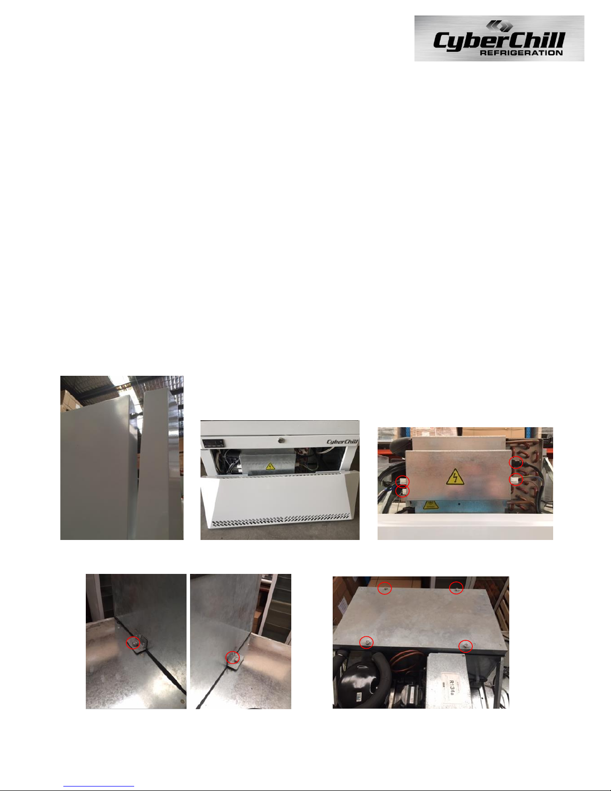
This product must be placed on a level floor to ensure the automatic
door closing and correct draining of condensate. Once in final position
lock the two front castors by pushing down on the extended tab.
V
e
ntil
a
tion
For efficient operation of the cabinet, it is essential that adequate ventilation be provided
around the refrigeration unit. The maximum recommended ambient temperature (at
place of installation) is 43°C, although the cabinet will generally use less power when
installed in a cooler location. Refrigeration equipment generates a lot of heat. Therefore,
it is very important that the cabinet must be installed with sufficient space around it for
ventilation and for maintenance access. Ventilation grills must not be blocked, or even
partially blocked as this could affect the cabinet’s performance and life span.

Shelves
The shelves may be positioned at different
heights to suit various products. Each shelf
is held in place by 4 shelf clips which engage
in the shelf support strips.
To Fit the shelves
1- Unpack the wire shelves and shelf clips
from inside the cabinet.
2- Establish the desired position for the
shelves and securely engage a
shelf clip in each of the shelf support
strips
3- Sit the shelves on the shelf support clips
Note: Remove some product if the shelves are flexing or bending
Gasket Re
pl
aceme
n
t
Damaged gaskets can easily be replaced. Remove the old
gasket by gently pulling it out of the gasket retainer and simply
push in the new gasket leaving the corners until last.
Replacing LED Light Tube
The cabinet has one interior side light.
The side light houses one 12 Watt T5 LED tube,
which may be replaced without removing shelves
or product from the cabinet.
1 - Disconnect the cabinet from the mains power
supply.
2 –Slide a thin flat head screw driver between the
diffuser and the edge its clipped into. Remove the
side light diffuser, by sliding the screw driver down
the full length of the cabinet until it disengages
from the aluminium housing and then lift the
diffuser out.
3 - The LED tube can now be removed. Revolve
the tube until the pin position allows withdrawal.
4 - When refitting the new LED tube ensure the
printing on the tube is at the bottom, as the tube orientation is important.
5 - When refitting the diffuser, engage the back section into the housing,
and then compress and snap the front section of diffuser back into place
working down the full length of the light.

Removing Cassette
Should maintenance be required on the cassette the following steps are to be followed;
1. Disconnect the cabinet from the mains power supply
2. Pull on the bottom of the kick panel to dislodge it from the cabinet (fig.1)
3. Lower the kick panel to remove and set aside (fig.2)
4. Using a flat head screw driver undo the 4 screws on the control fascia and remove (fig.3)
5. Using a Phillips head screw driver undo the outermost crews securing the lifting handles (fig.4)
6. Unplug the 4 plugs leading into the electrical compartment (fig.5)
7. Lower the handles to drop the cassette down and slide out to perform work (fig.6)
Fig.1
Fig.2
Fig.3
Fig.4
Fig.5
Fig.6

Removing Cassette –Top Mount
Should maintenance be required on the cassette the following steps are to be followed;
1. Disconnect the cabinet from the mains power supply
2. Pull on the top of the kick panel to dislodge it from the cabinet (fig.1)
3. Lift the kick panel to remove and set aside, this is recommended to avoid causing damage
(fig.2)
4. Unplug the 4 plugs into the electrical compartment (fig.3)
5. Undo the 2 bolts holding the cassette on to the cabinet with a number 13 spanner (fig.4)
6. The cassette can now be lifted off the cabinet
7. Should works only be required on the evaporator housing proceed with steps 1, 2, 3, 4 and
Then 8
8. Undo the 4 bolts holding the insulated lid, set aside and proceed with required works (fig.5)
NB: The cassette weight is approx. 40kg
Fig.1 Fig.2 Fig.3
Fig.4 Fig.5

Initial Start U
p
Plug the molded plug into a suitable socket. If
necessary, push the button on the controller to
start the unit. The cabinet air temperature will be
displayed once the unit is running. To standby the
unit when running, press and hold the button
for 3 seconds.
Display Legend
Operations
Checks
After initial start-up, the cabinet should start to pull down to the pre-set temperature,
check that the temperature is reducing and listen inside and outside the cabinet to
make sure the fans are turning freely to check there has been no movement in
shipping. If time permits, stay with the cabinet until the pre-set temperature is
reached and the condensing unit cuts out.
Using Your New Refrigeration
Equip
me
n
t
The cabinet must reach its preset operating temperature before loading any produce.
Ensure stored products are evenly distributed on shelves ensuring that no more than 40kg
are placed on each shelf. Cover all foods ensuring that cooked and raw foods are kept
separate to avoid cross contamination. To ensure even product temperature, it is
recommended that no food product is stored below the lowest shelf support.
Warm or hot food should never be stored inside the cabinet.
Foods containing acetic acids or yeast should be covered or ideally stored in airtight
containers otherwise premature failure of the refrigeration system may occur.

Commissioning Instr
u
c
tion
s
Refrigerators +1oC to +4
o
C
Temperature Se
tting
Refrigerators are designed to operate between +1oC and +4oC depending on the model.
The control is preset at the factory for this temperature and should require no
readjustment.
The temperature setting can be checked by unlocking the controller by pressing the
centre key twice . Once unlocked press the centre key again to display SP, press
the centre key again to display the set point.This setting can then be changed to better
meet site conditions by pressing the or buttons. (Refrigerators have a maximum
setting of 10oC and a minimum of -2C.) The temperature set is the cut out (stopping)
temperature; the cut-in (starting) temperature is determined by the differential.
Defr
o
st
ing
All CyberChill refrigerated cabinets are fitted with a fully automated defrost system that
ensures the cooling system remains free from ice under normal conditions. If a manual
defrost is required, this can be activated by pressing , for 2 seconds which will
terminate automatically once the pre-programmed temperature has been reached.

Fault
Finding
In the event of cabinet fault/failure, please check the following:
1. Plug is in socket and power to the socket can be proven by plugging another appliance
into the same socket or swapping the problem cabinet to a socket that is known to
work.
2. The condenser is clean and free from dust or debris.
3. Door gasket is sealing and free from damage.
4. Check if the evaporator is iced up, if found to be iced up push and hold to start
manual defrost.
If this doesn’t solve the problem, please call CyberChill on 1300 072 000.
When requesting a service call, please find the manufacturers data plate and provide the
model, serial number and details of any fault codes that are displayed.
Alarms
The controller is equipped with visual and audio alarms:
Alarm
Displayed
Descr
iption
Action Required
do
Door Open Alarm
Close door
hc
Condenser High Temperature Alarm
Check for blockage / clean
hi
High Temperature Alarm
Press a button to cancel / check
Lo
Low Temperature Alarm
Press a button to cancel / check
E1
Probe T1 Failure
Call Engineer
E2
Probe T2 Failure
Call Engineer
E3
Probe T3 Failure
Call Engineer
OFF
Cabinet In Standby
Press for 3 seconds
Press any button on the controller to silence an alarm.

Wiring Diagram

Notes:

Model: …………………………………………………………………….
Serial Number: …………………………………………………………
AUS Patent App. No. 2015201249
NZ Patent App. No. 705857
GWP Values for Refr
ig
era
n
ts:
R1234ze –<1
R290 –< 3
R134a –1430
R404a –3922
These units contain fluorinated greenhouse gases covered by the F Gas directive
Declaration of Conformity References:
Low Voltage Directive 2006/95/EC
EC Machinery Directive 2006/42EC
Electromagnetic Compatibility Directive 2004/108/EC
Pressure Equipment Directive 97/23/EC
RoHS / WEE Directive 2002/95 EC
This manual suits for next models
1
Table of contents