cybernetech CT-10G-MC series User manual

CT-10G-MC series
Media Converter
User’s Manual
CT-10G-MC Ver 1.1

2

3
Revision History
Date Version History
2011/05/06 1.0 First draft version
2011/08/01 1.1 Add XFP2 version

4
Table of Contents
Foreword..........................................................................................................................................2
Revision History..............................................................................................................................3
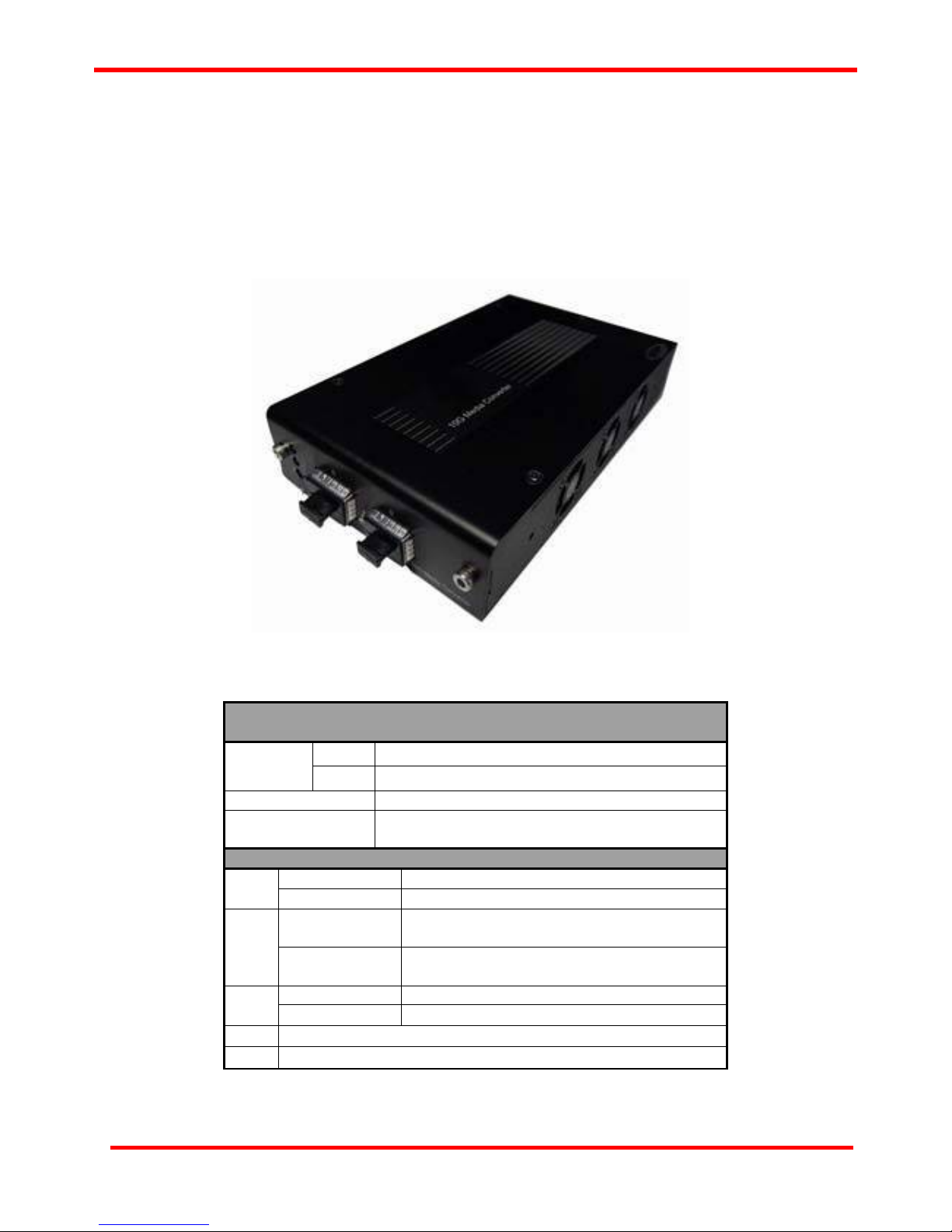
1. CT-10G-MC series Overview.......................................................................................................6
1.1. General Descriptions of CT-10G-MC ................................................................................6
1.2. Features, Key Advantages, and Main Applications of CT-10G-MC series ....................7
1.3. CT-10G-MC series Functions Overview ...........................................................................8
1.3.1. CT-10G-MC series Outer Case .....................................................................................8
1.3.2. CT-10G-MC series Front Panel.....................................................................................9
A. Front Panel of CT-10G-MC-SFP+2 series......................................................................9
B. Front Panel of CT-10G-MC-XSFP+ series ...................................................................10
C. Front Panel of CT-10G-MC-SFP+ series......................................................................11
D. Front Panel of CT-10G-MC-CX4 series........................................................................12
E. Front Panel of CT-10G-MC-XFP2 series......................................................................13
F. Front Panel of CT-10G-MC-XFP series.........................................................................14
1.3.3. CT-10G-MC series Back Panel ...................................................................................15
2. CT-10G-MC series Installation...............................................................................................16
2.1. Choices of UTP Cable and Optical fiber.........................................................................16
2.1.1. 10GBASE-T (Copper Wire)..........................................................................................16
2.1.2. 10GBASE-R (Optical Fiber).........................................................................................17
2.2. Connection of UTP Cable and Optical fiber...................................................................18
2.2.1. 10GBASE-T (Copper Wire)..........................................................................................18
2.2.2. 10GBASE-R (Optical Fiber).........................................................................................18
2.3. Applications Examples for Your Network.......................................................................20
2.3.1. Application for University...........................................................................................20
2.3.2. Application for Online Game Company.....................................................................21
2.3.3. Application for Home Users .......................................................................................22
3. CT-10G-MC series Management...............................................................................................23
3.1. Managing CT-10G-MC series with Management Webpage...........................................23
3.1.1. Accessing CT-10G-MC series Management Webpage.............................................24
3.1.2. CT-10G-MC series Management Webpage – Overview............................................25
3.1.3. CT-10G-MC series Management Webpage – System...............................................26
A. System Information ..........................................................................................................26
3.1.3. CT-10G-MC series Management Webpage – Management......................................27
A. IP Configuration ............................................................................................................27
B. User Settings.................................................................................................................28
C. System Configuration...................................................................................................28
D. SNMP Setting.................................................................................................................29
3.1.4. CT-10G-MC series Management Webpage – Counter..............................................29
A. Device Counter..............................................................................................................29
3.1.5. CT-10G-MC series Management Webpage – Maintenance......................................30
A. Save Changes................................................................................................................30
B. Update F/W (Firmware).................................................................................................30
C Update FPGA..................................................................................................................30
D. System Reboot..............................................................................................................31
E. System Config...............................................................................................................31
F. Config Upload ................................................................................................................31
G. Factory Defaults ............................................................................................................31
3.2. Managing CT-10G-MC series with HyperTerminal.........................................................32
3.3.1. HyperTerminal Settings for CT-10G-MC series.........................................................32
3.3.2. CT-10G-MC series HyperTerminal Commands.........................................................35
A. CT-10G-MC series HyperTerminal Command – system ............................................36
B. CT-10G-MC series HyperTerminal Command – counter ...........................................38
C. CT-10G-MC series HyperTerminal Command – ip .....................................................38
D. CT-10G-MC series HyperTerminal Command – cls....................................................39

5
E. CT-10G-MC series HyperTerminal Command – logout..............................................39
4. CT-10G-MC series General Specifications..............................................................................40

6
1. CT-10G-MC series Overview
1.1. General Descriptions of CT-10G-MC
CT-10G-MC series is a complete and versatile solution for applications such as FTTx, CWDM, and carrier
Ethernet. By the diversified speeds of 10Gbps, our provides standalone CT-10G-MC series for different
applications and can be applied according to your ideal network topology.
Our CT-10G-MC series provides various interfaces such as 10GUTP, SFP+, XFP and CX4. All these
interfaces are developed to support the protocols such as 10GBase-T, 10GBase-EZR, 10GBase-ZR,
10GBase-ER, 10GBase-LR, 10GBase-SR and 10GBase-CX4, thus making your network more complete
and solid.
All CT-10G-MC series are equipped with real-time LEDs which display the status of each port, thus allowing
users to view network status easily.
CT-10G-MC series provides an easy-to-access Management Webpage, allowing users to view system status,
counters, and network statistics.
Also, CT-10G-MC series supports MIB Counter Report including counters such as Packet, Byte, Broadcast
packet, Pause Frame, Length: 64 Bytes, Length: 65-127 Bytes, Length: 128-255 Bytes, Length: 256-511
Bytes, Length: 512-1023 Bytes, Length: 1024-1518 Bytes, Unicast packet, Multicast packet, CRC Error,
IP Checksum Error , Under size packet, and Over size packet.
With various interfaces, CT-10G-MC series provides different conversions between fibers and copper wires in
10Gbps Ethernet.

7
1.2. Features, Key Advantages, and Main Applications of CT-10G-MC series
Features
Diversified interfaces including SFP+, RJ45, XFP and CX4
Supports 3R (Re-generation, Re-timing, Re-shaping) Performance, both in STM-64 & OC-192
Supports Jumbo Frame
Supports DDI (Digital Detection) functioned optical transceivers and overload protection
Support easy-to-use Management Webpage that allows users to view system status, counters,
and network statistics
Supports SNMP (Simple Network Management Protocol)
Supports Link Loss Forwarding
Key Advantages
Fast connection with multi-function
Provide reliable long-distance connection
Port supported: SFP+, RJ45, XFP and CX4
Small portable size case
Plug and play without extra configuration
Main Applications
Media converter for network backbone
Connection between fiber to copper or fiber to fiber 10Gbps Ethernet equipment
Can be applied in Telecommunication room, R&D laboratory, Data center, and etc.

8
1.3. CT-10G-MC series Functions Overview
1.3.1. CT-10G-MC series Outer Case
CT-10G-MC series’ outer case consists three parts: Front Panel, Cooling Fan, and Back Panel. The figure
above shows the outer case of CT-10G-MC-CX4 series. Outer cases of other CT-10G-MC series are quite
the same and can be related.
CT-10G-MC series Outer Case Overview
Front Panel CT-10G-MC series comes with various different types of ports, providing media
converting platforms for different types of media. Please see “1.3.2. CT-10G-MC
series Front Panel”for more detailed information.
Cooling Fan Cooling fan for ventilation. All CT-10G-MC series have cooling fans installed.
Back Panel
CT-10G-MC series’ back panels allow users to access their management web
pages or making configurations via hyper terminal softwares.Also, CT-10G-MC
seriespower jack is located on the back panel as well. Please see “1.3.3.
CT-10G-MC series Back Panel” for more detailed information.
Cool Fan
CL-MC-CX4 back panel
CT-10G-MC-CX4 Front panel

9
1.3.2. CT-10G-MC series Front Panel
As mentioned in “1.3.1. CT-10G-MC series Outer Case”, CT-10G-MC series comes with various different
types of ports, providing media converting platforms for different types of media. Please see the sections
down below for more detailed information/specification for CT-10G-MC series.
A. CT-10G-MC-1 series
CT-10G-MC-1 series Front Panel Specification
Port A SFP+
Interface Port B SFP+
Data Transfer Rate 10Gbps
Ethernet Mode 10GBase-LR
10GBase-SR
LED Status
Green ON CT-10G-MC-1 series is power on.
Power Green OFF CT-10G-MC-1 series is power off.
Green ON CT-10G-MC-1 series is booting
properly and is ready for tests.
SYS Yellow ON Error occurred when booting
CT-10G-MC-1 series.
Green ON Port A/B is connected.
A/B Green Blinking Port A/B is transmitting/receiving data.
▇User-defined LED
▲User-defined LED

10
B. CT-10G-MC-2 series
CT-10G-MC-2 series Front Panel Specification
Port A SFP+
Interface Port B XFP
Data Transfer Rate 10Gbps
Ethernet Mode 10GBase-LR
10GBase-SR
LED Status
Green ON CT-10G-MC-2 series is power on.
Power Green OFF CT-10G-MC-2 series is power off.
Green ON CT-10G-MC-2 series is booting
properly and is ready for tests.
SYS Yellow ON Error occurred when booting
CT-10G-MC-2 series.
Green ON Port A/B is connected.
A/B Green Blinking Port A/B is transmitting/receiving data.
▇User-defined LED
▲User-defined LED

11
C. CT-10G-MC-3 series
CT-10G-MC-3 series Front Panel Specification
Port A RJ45
Interface Port B SFP+
Data Transfer Rate 10Gbps
Ethernet Mode 10GBase-LR
10GBase-SR
10GBase-T
LED Status
Green ON CT-10G-MC-3 series is power on.
Power Green OFF CT-10G-MC-3 series is power off.
Green ON CT-10G-MC-3 series is booting properly
and is ready for tests.
SYS Yellow ON Error occurred when booting
CT-10G-MC-3 series.
Green ON Port A/B is connected.
A/B Green Blinking Port A/B is transmitting/receiving data.
▇User-defined LED
▲User-defined LED

12
D. CT-10G-MC-4 series
CT-10G-MC-4 series Front Panel Specification
Port A CX4
Interface Port B SFP+
Data Transfer Rate 10Gbps
Ethernet Mode 10GBase-LR
10GBase-SR
10GBase-CX4
LED Status
Green ON CT-10G-MC-4 series is booting properly
and is ready for tests.
SYS Yellow ON Error occurred when booting
CT-10G-MC-4 series.
Green ON Port A/B is connected.
A/B Green Blinking Port A/B is transmitting/receiving data.

13
E. CT-10G-MC-5 series
CT-10G-MC-5 series Front Panel Specification
Port A XFP
Interface Port B XFP
Data Transfer Rate 10Gbps
Ethernet Mode 10GBase-LR
10GBase-SR
LED Status
Green ON CT-10G-MC-5 series is power on.
Power Green OFF CT-10G-MC-5 series is power off.
Green ON CT-10G-MC-5 series is booting properly
and is ready for tests.
SYS Yellow ON Error occurred when booting
CT-10G-MC-5 series.
Green ON Port A/B is connected.
A/B Green Blinking Port A/B is transmitting/receiving data.
▇User-defined LED
▲User-defined LED

14
F. CT-10G-MC-6 series
CT-10G-MC-6 series Front Panel Specification
Port A RJ45
Interface Port B XFP
Data Transfer Rate 10 Gbps
Ethernet Mode 1000Base-T
10GBase-LR
10GBase-SR
LED Status
Green ON CT-10G-MC-6 series is power on.
Power Green OFF CT-10G-MC-6 series is power off.
Green ON CT-10G-MC-6 series is booting properly and
is ready for tests.
SYS Yellow ON Error occurred when booting CT-10G-MC-6
series.
Green ON Port A/B is connected.
A/B Green Blinking Port A/B is transmitting/receiving data.
▇User-defined LED
▲User-defined LED

15
1.3.3. CT-10G-MC series Back Panel
A B C
CT-10G-MC series Back Panel Description
A Management Port 100 Mbps RJ45 Management Port for connecting
CT-10G-MC series to a network, thus allowing users
to access CT-10G-MC series’ management web pages
B Diagnostic Port 2.5mm Phone Jack for connecting PC’s RS 232
port, thus allowing users to make configurations
via hyper terminal softwares.
C Power Jack DC 12 V Power Jack

16
2. CT-10G-MC series Installation
As a media convertor platform, installing CT-10G-MC series is very easy and simple: all you have to do is to
plug the proper fiber/UTP cables into CT-10G-MC series’ ports like a general Ethernet switch without any extra
configurations. However, selecting the proper physical media and applications in your network
environment is crucial when installing CT-10G-MC series. Please see the sections down below for detailed
information regarding to physical media types and CT-10G-MC series application.
2.1. Choices of UTP Cable and Optical fiber
2.1.1. 10GBASE-T (Copper Wire)
10GBASE-T, or IEEE 802.3an-2006, is a standard released in 2006 to provide 10 gigabit/second
connections over unshielded or shielded twisted pair cables and over distances up to 100 meters (330 ft).
10GBASE-T cable infrastructure can also be used for 1000BASE-T, allowing a gradual upgrade from
1000BASE-T, and auto-negotiation to select which speed to use.
10GBASE-T Connectors
10GBASE-T uses 650 MHz versions of the venerable IEC 60603-7 8P8C (RJ-45) connectors, which is
already widely used in Ethernet.
10GBASE-T Cables
10GBASE-T works up to 55 m (180 ft) with existing Category 6 cabling. In order to allow deployment at
the usual 100 m (330 ft), the standard uses a new partitioned Category 6a cable specification, designed
to reduce crosstalk between UTP cables.
The table down below is a reference regarding to UTP cable categories.
UTP Cable Categories References
Cat 5 Provides performance of up to 100 MHz, and was frequently used on 100 Mbps Ethernet
networks. Cat 5 may not be suitable for 1000BASE-T gigabit Ethernet.
Cat 5e Provides performance of up to 100 MHz, and is frequently used for both 100 Mbps and
Gigabit Ethernet networks.
Cat 6 Provides performance of up to 250 MHz, more than double of category 5 and 5e. It works up
to 55 m (180 ft) for 10Gbps Ethernet.
Cat 6a
Provides performance of up to 500 MHz. It is suitable for
10GBASE-T and works up to 100 m (330 ft) for 10Gbps
Ethernet. All the cables mentioned above do not have
individually- shielded pairs as the picture here, including
Cat 6a.
Cat 7 This standard specifies four individually-shielded pairs (STP) inside an overall shield.
Designed for transmission at frequencies up to 600 MHz. It has better performance than Cat
6a.

17
2.1.2. 10GBASE-R (Optical Fiber)
10GBASE-R is 10Gbps Ethernet connection that based on IEEE802.3ae. It uses fiber as transmission
media with different specification of fiber, connector and transceiver. CT-10G-MC series uses two standards,
10GBASE-LR and 10GBASE-SR.
10GBASE-SR
10GBASE-SR ("Short Range") uses 64B/66B encoding and 850 nm wavelength lasers. It is designed to
support short distances over deployed multi-mode fiber cabling, it has a range of between 26 meters (85
ft) and 82 meters (270 ft) depending on cable type. It also supports 300 meters (980 ft) operation over
new, 50 μm 2000 MHzkm OM3 multi-mode fiber (MMF).
The transmitter can be implemented with a VCSEL (Vertical Cavity Surface Emitting Laser) which is low
cost and low power. MMF has the advantage of having lower cost connectors than SMF (single-mode
fiber) due to its wider core.
10GBASE-SR delivers the lowest cost, lowest power and smallest form factor optical modules.
10GBASE-LR
10GBASE-LR ("Long Range") is a Long Range Optical technology delivering serialized 10 gigabit
Ethernet over a laser with 1310 nm wavelength connection on single-mode fiber via IEEE 802.3 Clause
49 64B-66B Physical Coding Sub layer (PCS) using a line rate of 10.3125.
Single-mode optical cabling is used to interconnect transceivers at a distance spaced at 10 kilometers
(6.2 mi), but it can often reach distances of up to 25 kilometers (16 mi) with no data loss.
Fabry–Pérot lasers are commonly used in 10GBASE-LR optical modules. Fabry–Pérot lasers are more
expensive than VCSELs (mentioned above) but their high power and focused beam allow efficient
coupling into the small core of single mode fiber.
Fiber Specification
Fibers which support many propagation paths or transverse modes are called multi-mode fibers (MMF).
Fibers which can only support a single mode are called single-mode fibers (SMF). Multi-mode fibers
generally have a larger core diameter, and are used for short-distance communication links and for
applications where high power must be transmitted. Single-mode fibers are used for most
communication links longer than 200 meters.
Fiber Buffer/Jacket Color Meaning
Yellow Single-mode optical fiber, long distance connection
Orange Multi-mode optical fiber, short distance connection

18
2.2. Connection of UTP Cable and Optical fiber
2.2.1. 10GBASE-T (Copper Wire)
10GBASE-T uses the same RJ45 connector that is the same as original 100M/1000Mbps Ethernet
network. Just plugging the RJ45 connector into the port of 10Gbps and it is ready to work. When
connected properly, the Link/ACT LED located under the RJ45 Port will be on accordingly. 10G UTP
need apply Cat6a or Cat7 cable.
2.2.2. 10GBASE-R (Optical Fiber)
Please see the figure down below for connecting the optical fiber, transceiver, and CT-10G-MC series’ SFP+
Port.
PLUG SFP+ transceiver into 10G Media converter

19
Optical Fiber
As mentioned above, there are Single-mode and Multi-mode optical fiber. Both of them can be used for
CT-10G-MC series .
Fiber Connector
Optical fiber connector contains two ends of fibers and can attach
to SFP+ transceivers. There are two ports for one SFP+
transceiver: one fiber is for receiving and one fiber is for
transmitting. The picture here is called LC connector that can
attach to SFP+ transceiver.
Transceiver (Connector)
SFP+/XFP Transceivers can be plugged into CT-10G-MC series’ SFP+/XFP Ports. SFP+/XFP Transceivers
are active components that consume power from CT-10G-MC series and are capable of converting signals
between optical data flow and electronic data flow.
For different transmission purpose, the component inside SFP+ form factor can be 10BASE-SR, LR, ER,
ZR, EZR, mode.

20
2.3. Applications Examples for Your Network
2.3.1. Application for University
10Gbps speed Ethernet connection may not be commonly seen in ordinary offices. However, network
administrators may have Gigabit Ethernet in their control rooms already. Getting 10Gbps Ethernet
connection from Internet Backbone and distributing it to different Gigabit Ethernet segment for different
buildings or organizations is practical and more cost-effective. Figure down below is an example of a
possible network structure for a university:
Descriptions
A Internet backbone from ISP.
B The distance from the central office to the university might be long, and it is advised to construct the
connection via single-mode optical fiber with 10BASE-LR mode, which can extend the distance
beyond tens of kilometers.
C CT-10G-MC series, which is located at the computer center of university.
D After the conversions made by CT-10G-MC series, expensive equipments for
transmitting/receiving network data via optical fiber are not required anymore.
E Full 10Gbps Ethernet switches may be exceeding your budget or not available. Some 1Gbps
switches reserve a swappable slot for future upgrading. You can purchase a 10Gbps module with
one 10Gbps port for these switches to serve the same purpose.
F Several 1Gbps connections can be distributed by the switches mentioned above to different
buildings inside the university by Cat 6a network cables (which can be extended to 100 meters).
G/H/I General switches with 1Gbps or 100Mbps ports can be connected here for the end-users.
Table of contents