Cyfre CBAHP800 User manual

Cellular In-Building Amplifier Installation
Manual
Page 1 of 4
All brands and trademarks are the property of their respective owners. Copyright
2003, Janizary Holdings, Inc. All rights reserved. 11/16/05
Rev A D000003
Designed and manufactured under license from Motorola, Inc. in the USA
Note: Before installing the Cyfre™ Amplifier, please read the entire contents of this manual.
Section # 1 Parts List
Ite
m
Q
ty
Description
1
1
Cyfre™ Amplifier
2
1
Cyfre external antenna
3
4
5
1
1
1
Cyfre interior antenna with 4 meters of low loss antenna cable
Cyfre 120 VAC power supply
Cyfre 4 meter low loss antenna cable with “N” connectors
Section # 2 Tools and Other Materials Required
Item
Description
1
Electric drill (as required for amplifier mounting holes, and external antenna mounting)
2
Chisel and Phillips Screw drivers, 8mm and 10mm wrenches
3
Qty 8 fasteners (length and type as required for amplifier and external antenna mounting)
4
Wire cutters / strippers
5
Cables ties for clamping the external and interior antenna cables to rigid structure
Section # 3 WARNINGS!
∇Antennas must be mounted a minimum distance of 50 cm (1.64ft) away from any person.
∇When selecting a location for the interior antenna a minimum distance of 6 feet (1.82m) distance away from the amplifier.
∇When 2 or more antennas are located in the same area they must be mounted at different heights to insure optimum performance.
∇Exterior antennas can only be installed outdoors. Under no circumstances can an exterior antenna be installed indoors, Doing so will result
in amplifier failure and void the warranty.
∇The power supply must be plugged into a 120 VAC electrical outlet that is connected to a circuit breaker of a minimum of 1 ampere.
∇Under no circumstances should the amplifier be powered up without a properly connected 50 ohm 800/ 1900 MHz dual band cellular
antenna connected to both the internal and external connections or the amplifier may be damaged, resulting in the manufacturer’ warranty
being voided.
∇For optimum performance and compatibility with cellular service provider requirements, it is recommended that the external antenna be
installed above the roofline of a building with a clear view of the surrounding area
∇Use of cellular amplifiers with antennas of higher gains than 15dBi gain is in violation of FCC regulations for which the offender will be fully
liable, and warranty claims will be voided.
∇Do not extend the external antenna cable with another coaxial cable. The additional loss of the cable length and connectors will greatly
diminish the performance of the amplifier.
It is recommended that only qualified or informed installation technicians install this product in a building.
Installation by any other person is at the risk of the owner and operator.

Cellular In-Building Amplifier Installation
Manual
Page 2 of 4
All brands and trademarks are the property of their respective owners. Copyright
2003, Janizary Holdings, Inc. All rights reserved. 11/16/05
Rev A D000003
Designed and manufactured under license from Motorola, Inc. in the USA
Section # 4 Installation Cautions
∇Use caution to avoid drilling through or near electrical, water or gas lines.
∇Do not mount the signal amplifier or its associated wiring in a location that may contain hazardous materials or materials
that are corrosive.
∇Do not attempt to ground the external antenna. It is designed with its own interior ground system.
∇The interior antenna requires a ground plane. It should be mounted on any type of metal that will have a minimum of one
square foot of surface area under the antenna base.
∇Caution: DO NOT INSTALL THE INTERIOR ANTENNA IN A HAZARDOUS LOCATION THAT MAY
CONTAIN ANY TYPE OF VOLITILE VAPORS.
Section # 5 Selecting a Suitable Location To Install The Amplifier
∇Locate a suitable place to mount the cellular band amplifier. For exterior antennas you must mount the antenna above the
roofline of the building at a distance that can be reached from the supplied external antenna cable, on a shelf near a
electrical power source, in a dry area that is well ventilated. The amplifier’s location should be easily accessible and
mounted away from moving parts, as well as excessive heat and moisture.
∇Antennas must be mounted a minimum distance of 50 cm (1.64ft) away from any person.
∇When selecting a location for the interior antenna a minimum distance of 6 feet (1.82m) distance away from the amplifier.
∇When 2 or more antennas are located in the same area, they must be mounted at different heights to insure optimum
performance.
∇Exterior antennas can only be installed outdoors. Under no circumstances can an exterior antenna be installed indoors,
Doing so will result in amplifier failure and void the warranty.
∇If the signal level is increased in some areas but not others, it may be due to location of interior antenna or building
materials acting as a shield for the radio signals. This can be overcome by re-positioning the interior antenna or, the use of
2 internal antennas in conjunction with a very low loss high quality splitter. Please note that the interior antennas must be at
least twenty five (25) feet apart and should be separated by gypsum clad, masonry or metal constructed wall.

Cellular In-Building Amplifier Installation
Manual
Page 3 of 4
All brands and trademarks are the property of their respective owners. Copyright
2003, Janizary Holdings, Inc. All rights reserved. 11/16/05
Rev A D000003
Designed and manufactured under license from Motorola, Inc. in the USA
Typical Installation For the Cyfre™ In-Building Amplifier Series
Section # 6 Installation Of The Cellular In-Building Amplifier
1. Unpack the box with the amplifier, power supply, external antenna, antenna cable and interior antenna.
2. The first item is to find a suitable location for the exterior antenna, which will give a clear view without obstruction, and also
allow the antenna cable to penetrate either the roof area or a wall area below the roofline.
3. The exterior antenna contains two mounting brackets, a mounting tube, three sets screws, two 5 mm, and one 6mm, and
the actual antenna. (see figures below)
4. Slide the two mounting bracket on to the mounting tube, tighten the center mounting screws, 5 mm, (8mm wrench required)
hand tight when the brackets are within 2 inches of the top and bottom of the mounting tube. When the assembly is
mounted to the wall surface, make certain the center-mounting hole of the mounting tube is facing outward.
5. Mark the wall surface through the four holes of the mounting brackets.
6. Drill the holes for the mounting brackets and use masonry fasteners, self-tapping screws or bolts to mount the mounting
brackets and tube to the wall surface.
Use a 3dB antenna for
Optimal Performance

Cellular In-Building Amplifier Installation
Manual
Page 4 of 4
All brands and trademarks are the property of their respective owners. Copyright
2003, Janizary Holdings, Inc. All rights reserved. 11/16/05
Rev A D000003
Designed and manufactured under license from Motorola, Inc. in the USA
Section # 6 Installation Of The Cellular In-Building Amplifier (Continued)
7. Attach one end of the RF Coaxial cable with the N connectors to the antenna.
8. Slide the cable through the mounting tube and push the antenna into the top of the tube until the locking threaded hole in
the antenna base lines up with the mounting tube hole.
9. Place the 6 mm bolt through the mounting tube hole, with the lock washer and tighten the assembly. (requires 10 mm
wrench)
10. Drop the antenna cable through either the roof, or wall penetration into the area below the roofline. Seal all penetrations with
either a mechanical device or with some form of silicon sealer.
11. Drill holes or Velcro tape and mount the signal amplifier (ITEM 1) in the selected location.
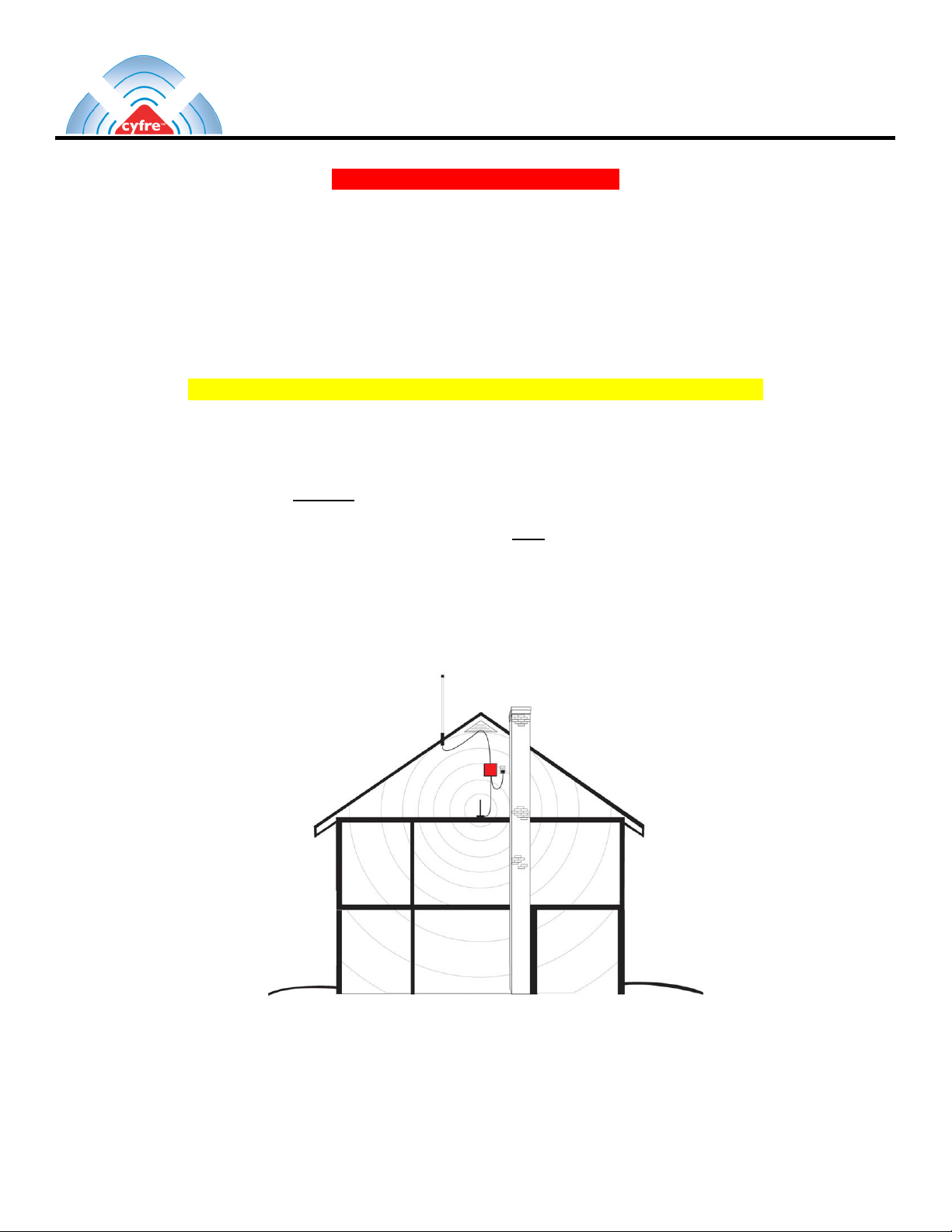
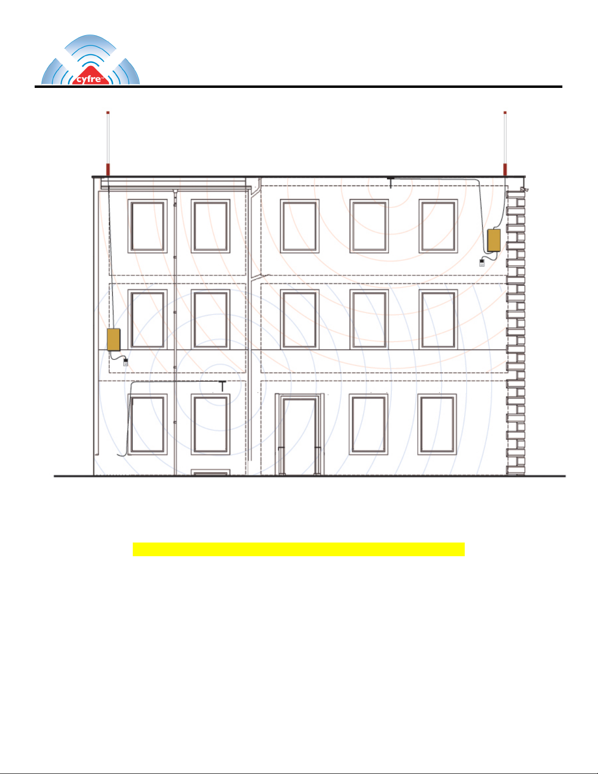
12. Place the interior antenna as central to the building as possible.
13. Place the antenna on a metal sheet 12 inches by 12 inches or larger on shelf or any other flat dry surface for a good ground
plane. Make sure that the inside antenna is at least four (6) six feet or more below the external antenna in a vertical
measurement. Never attempt to install the Interior antenna in the same horizontal plane as the external antenna.
14. Connect the external coaxial antenna cable to the “External Antenna” connection on the amplifier case marked “exterior
antenna” This will be on the side with no power LED light or power input.
15. Connect the inside antenna to the “Interior Antenna” connection on the side of the amplifier case that has the power LED
light and power input.
16. Insert the 2.5 x 5.5 mm power plug from the power supply (ITEM 4) into the amplifier input next to the power LED light.
17. Insert the power supply to wall 120 VAC power.
18. Make sure the power light comes on the amplifier.
19. The installation is now complete.
Antenna assembly drawing:
Section # 7 Limited Warranty
Cyfre™ warrants that this product is free from any defects in material or workmanship for a period of one year.
If a defect in material or workmanship is found, Cyfre™ agrees to repair or replace the product at its own
discretion, free of charge to the original purchaser excluding all shipping charges. Please return the product
along with proof of purchase to the original authorized dealer. This warranty is null and void if the product has
been modified, abused, tampered with, or subjected to abnormal conditions. Any use of non Care™ antennas or
cables will void this warranty.
Table of contents
Other Cyfre Amplifier manuals