CA819
Dual Band Amplifier Installation Manual Page 2 of 2
All brands and trademarks are the property of their respective owners.
Copyright 2007, Janizary Holdings, Inc. All rights reserved.
Rev F D00000415
Designed and manufactured in North America
Manufactured under license from Motorola Inc.
∇You may place your amplifier anywhere inside your vehicle (except as mentioned above). The amplifier’s location should be easily
accessible and mounted away from moving parts, excessive heat or moisture.
∇The exterior antenna must be mounted outside the vehicle and at a distance that can be reached from the supplied antenna cable.
Section # 5 Installation Cautions
∇Use caution to avoid drilling through or near fuel lines or fuel tanks; brake lines; or electrical wiring.
∇Do not mount the amplifier or its associated wiring in a location that may interfere with the safe operation of the vehicle.
∇If the fuse is changed from the 3 amps to a higher rating the warranty is void. Purchaser of the amplifier would be responsible for
the repair of the unit.
∇Caution: Connection to the negative side with the positive lead will cause damage to the amplifier.
Section # 6 Installation of In-Vehicle Amplifier
To meet the FCC Exposure Guidelines, the antenna should be installed so there is at least 20 cm of separation between the body of the user
or nearby persons and the antenna.
Typical Installation For Under the Seat Mounting
1. For safety, disconnect the vehicle’s negative “−“battery terminal to remove power from the vehicle.
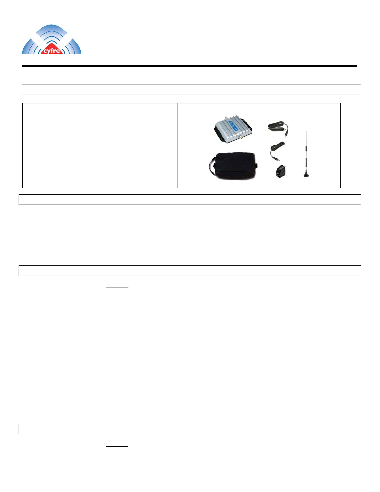
2. Drill holes and mount the signal amplifier (ITEM 1) in the selected location.
3. Connect the red wire of the supplied 2 Meter (78”) power cable (ITEM 2) for the signal amplifier to a positive connection on the vehicle’s
electrical system. Choose a 10 to 30 Volt DC circuit that is: fuse protected; and ignition switched. (Often referred to as the “Accessory
output”)
4. Attach the solid black wire of the supplied 2 Meter (78”) power cable (ITEM 2) to a vehicle electrical ground point.
5. Attach an external antenna cable (6dbi max) to the amplifier's antenna connector. The “Phone” connector on the amplifier is connected to a
cellular phone handset via a RF cradle or an RF cable. You may also connect the optional RF cable for your handset, from the cellular
handset to amplifier port labelled “Phone”.
6. Reconnect the vehicle’s negative “−“ Battery terminal.
Section # 7 Limited Warranty
Cyfre™ warrants that this product is free from any defects in material or workmanship for a period of one year. If a defect in
material or workmanship is found, Cyfre™ agrees to repair or replace the product at its own discretion, free of charge, to the
original purchaser excluding all shipping charges. To return product, all parts, packaging, and accessories along with original
receipt from where you purchased your product must be included with your return. Failure to return all product, parts,
packaging, and accessories will result in voiding your warranty. The warranty is void if the product has been modified,
abused, tampered with, or subjected to abnormal conditions. Any use of non Cyfre™ antennas or cables will void your
warranty.
Cyfre™
·
2282
Townsgate
Road
·
Building
1
·
Westlake
Village,
California
·
91361
·
tel:
805-777-1100
·
fax:
805-777-8232
·
ema
il: [email protected]
Use a 3dB
antenna for
Optimal
Performance