Cymbol G3 Series User manual

4 Channel Video Recorder
Quick Guide
Smart Secure Technology™
™
Series
™

1. Hardware Overview
This installation guide provides detailed information and instructions for the HNR-E10450 /
HNR-E20450 Network Video Recorder.
• Front View
REC LED : Emitting during recording
Power LED : See ** below
Power On/Standby button
** Power status
Red : Standby state
Orange : In booting progress
Green : Normal state
Network LED : Emitting when Ethernet cable connected
• Right Side View
• Left Side View
Sata hard disc drive
Extra Sata connector : To expand hard disc drive
adding to installed drive inside
1 USB Port : To connect external hard disk
drives for data backup.
2

• Rear View
- 2.4GHz wireless antennas
WiFi Antennas
8 Ports Sensor In
p
ut
- NO Devices
- DC 30V 1A max
- AC 125V 0.5A max
8 Ports Alarm Out
p
ut
- NC/NO Devices selectable
- TTL Level Input
** Only working with wireless antennas
WPS Button :
To automatic detect and
connect to wireless cameras
Reset Button :
To return all configurations
to factory default values
RS232 Port :
To connect devices
such as POS
Gigabit Ethernet Port :
To connect to IP cameras
and Client software
3

2. Installation
2.1 Connecting Power and Network
• Connecting to the RJ-45
Connect a standard RJ-45 cable to the network port of the broadband router (or Network
Switch) and the other end of the cable to the network port on the NVR.
HNR-E20450
Network Connections
Example Broadband Router
4

• Connecting Alarms
Alarm Input :
You can use external devices to signal the network camera to react on events.
Mechanical or electrical switches can be wired to the Alarm Input 1~8 and GND
(Ground) connectors.
GND(Ground) :
Connect the ground side of the alarm input to the G (Ground) connector.
Alarm Output :
The network camera can activate external devices such as buzzers or lights. Connect
the devices to the Alarm Output 1~8 and C(Common) connectors.
• Connecting the Power
Connect the DC power adaptor to the NVR. As the power is supplied, the Power LED
will start flickering, indicating stand-by mode. Pressing the POWER button will turn
the power on and the Power LED will light.
5

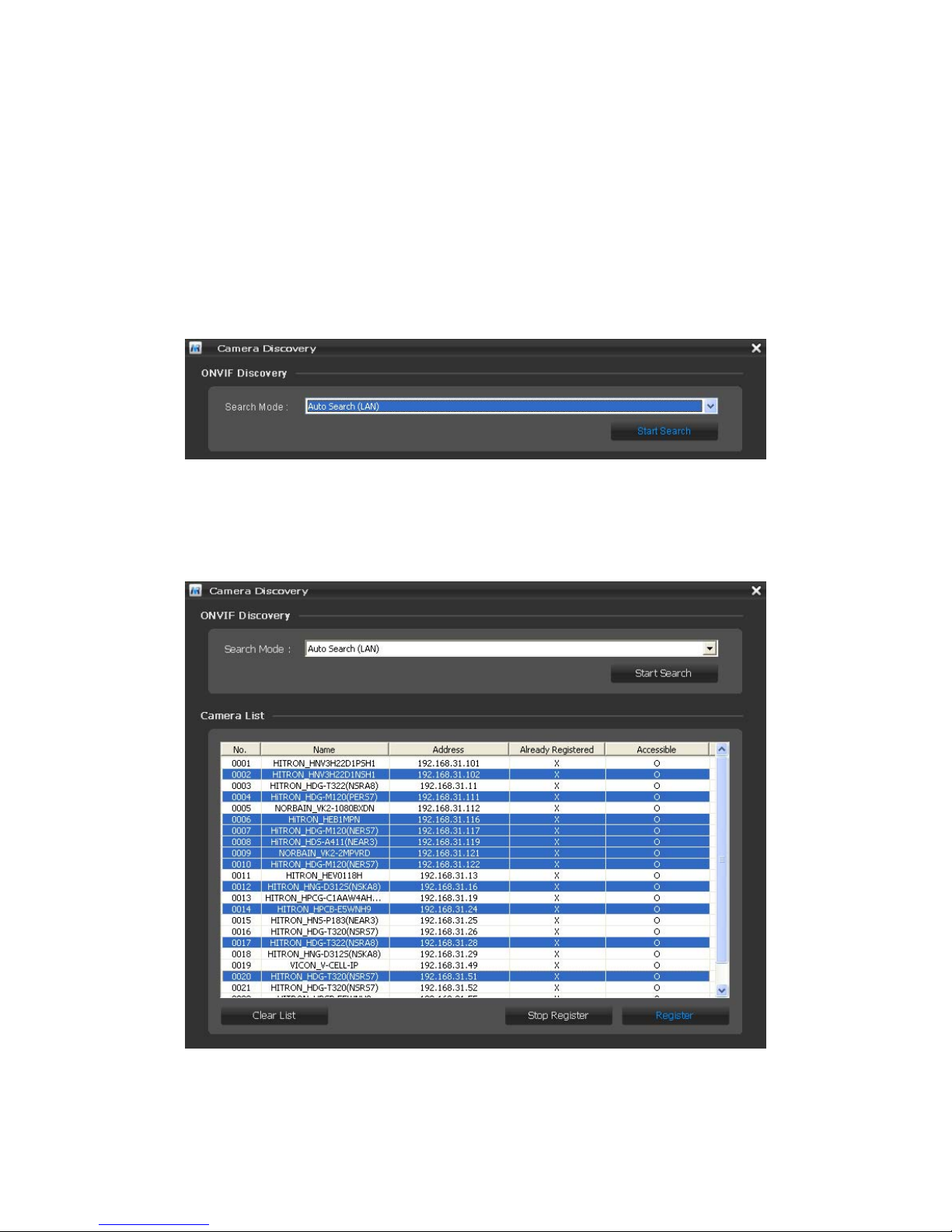
2.2 Discovering the NVR
The Network Video Recorder supports operation through the network. When the NVR is first
connected to the network it has an IP address assigned to it by your broadband router. So, it
is not necessary to allocate an IP address.
Contained on the CD supplied is a program called Smart Manager. Smart Manager detects
IP devices on your network. Using a windows machine connected to your network (Wireless
or Wired Connection), install smart manager.
1. Ensure the NVR is connected the broadband router and powered up.
2. Start SmartManager utility, the main window will be displayed, after a short while any
network devices connected to the network will be displayed in the list.
3. To access the NVR double click on the NVR listed in the Smart Manager, this will
automatically launch the Internet Explorer and display the login window for the NVR.
Please Note – Depending on your computer setup, you may be requested to install an
internet explorer add-in. Please select yes or install when prompted.
6

2.3 Connecting to the NVR Manually
1. Start a browser (Internet Explorer).
2. Enter the IP address or host name of the Network Video Recorder in the
Location/Address field of your browser.
3. If the NVR has not been configured, Setup Wizard will be shown. This drastically
reduces the time required for system installation. Images from cameras are connected
and recorded automatically to the NVR, so that you can start monitoring and recording
instantly.
Default Username and Password
Username: admin
Password: admin
7

2.4 Setup Wizard
[Step1]
The Setup Wizard window will be shown if you are accessing the NVR for the first time.
Enter the date and time settings. You can select to synchronize the server time with an
internet time server. If you enter a domain name for the NTP server.
8

[Step2]
Easy Installation means the NVR will detect Vista VK2 cameras wired to your broadband
router and register them automatically.
You can change the admin password or use the default password (admin) for cameras to be
detected.
If you don’t want to use Easy Install function, click the checkbox.
Click the Next button to go to next page.
[Step3]
The NVR displays any cameras already connected to the NVR if no cameras are displayed
you may need to search for the cameras.
9

Click the Search Cameras button and the Camera Discovery window appears. Select one
of three in Search Mode and click the Start Search button.
• Search Mode:
- Auto Search (LAN): Lists cameras in a LAN environment. (Recommended)
- IP Search (Single): Allows you to enter the IP address of a device. You can
search more than one device at a time by entering a range of IP addresses.
- Domain Name Search: Allows you to enter the domain name registered on a
DDNS server if the camera uses the DDNS function.
All cameras detected are displayed in the list. Display the name and IP address the
selected camera. The name will be updated automatically depending on the settings of
the network camera.
10
Other manuals for G3 Series
7
Table of contents
Other Cymbol DVR manuals


