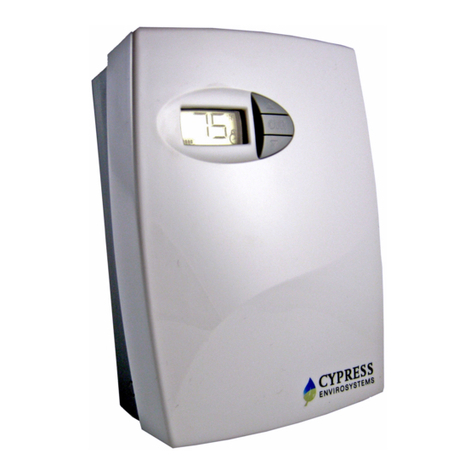
Cypress WPT Use and care manual

Tech note: WPT Battery Replacement
Doc No. 910-00022-01 Rev 01
Page 1 of 7
1. Overview
This technical note describes the Wireless Pneumatic Thermostat (WPT) battery
replacement procedures presented in a bulleted list of simple steps. This technical
note covers thermostats with current as well as older firmware versions. A
troubleshooting section provides the necessary steps to reset the WPT if any non-ideal
behavior is noticed.
1.1. Tools Required for Installation
•1/16” hex Allen wrench
•2mm hex Allen wrench (older versions)
2. Battery Replacement
The WPT has a battery icon on the LCD display which indicates the current state of the
batteries. Batteries must be replaced anytime the battery icon displays fewer than 4
bars as shown in Figure 1 below.
Figure 1: Low Battery Icon Examples with Fewer than 4 Bars Displayed
When the batteries are too low to function normally, the WPT will enter a fail-safe mode
(Figure 2) until batteries are replaced. The fail-safe mode shuts down all functions of
the WPT except for temperature control which continues to operate at a setpoint of 72
ºF.
Figure 2: LCD Display during the Fail-Safe Mode
Note: With older generation WPT thermostats, the device may go directly to a blank
display and/or stop responding to button presses.
2.1. Battery Installation
After replacing batteries, following tasks must be performed:
•Press any button to power on the WPT.
•Perform a Force Discovery. Refer to Figure 4 or Figure 8 for the menu structure.
•Perform a manual calibration, Refer to section 2.3.1or 2.3.2.
•(Optional) Resend temperature setpoints, setpoint limits and auto calibration
values from the WPT Green Box Controller. Refer to the appropriate WPT Green
Box manual for instructions.
Note: If any of the steps above fail, refer to Section 3 (Troubleshooting) for further
details.

WPT Battery Replacement Tech Note
Doc No. 910-00022-01 Rev 01
Page 2 of 7
2.2. Battery Handling Precautions
Figure 3: WPT Batteries
Only replace battery with Type CR123A that meets UL-1642, as evidenced by UL
component recognition mark (from Panasonic, Energizer or Duracell). Use of any other
battery may present a risk of fire or explosion. See Figure 3 for correct polarity.
•Underwriters Laboratories Recognition Mark:
•Caution: The battery used in this device may present a fire or chemical burn
hazard if mistreated. Keep away from children and/or other untrained personnel.
Do not recharge, disassemble, heat above 100 ºC (212 ºF), or dispose of in fire.
•Dispose of used battery promptly in accordance with local regulations (place in
plastic bag and recycle if possible).
•Do not insert batteries with the and polarities reversed.
•Do not short-circuit.
•Be sure to wrap each battery when disposing or storing to avoid short circuit.
•If leaked liquid gets in the eyes, wash them with clean water and consult a
physician immediately.
•Do not use new and used batteries together. Do not use different types of
batteries together.
•Do not apply strong pressure to the batteries nor handle roughly.
•Do not use or leave the batteries in direct sunlight or in high-temperature areas.
2.3. Calibrating the WPT
Remove the front cover of the WPT and make sure that the WPT is acclimatized to the
ambient temperature.
NOTE: Keep hands and breathe away from the WPT to minimize calibration error.
NOTE: The black throttling range adjuster has been factory set to the location marked
on the lever as shown in Figure 6. The factory setting provides a Throttling
Range (TR) of 4°F. This TR adjuster MUST NOT BE MO VED to ensure proper
operation and accuracy of the WPT.

Tech note: WPT Battery Replacement
Doc No. 910-00022-01 Rev 01
Page 3 of 7
Figure 4: WPT Menu Structure (FW v25.00 and higher)

Tech note: WPT Battery Replacement
Doc No. 910-00022-01 Rev 01
Page 4 of 7
2.3.1. WPT firmware v25.00 or higher
1. To enter Calibration Mode, perform the following:
2. Press the ▼button and OVR button together for two seconds. The display will show
‘dt’.
3. Press OVR four times. The LCD displays the branch pressure in PSI along with
PRESSURE indicator. The display shows “--" if the motor is in motion when trying to
access branch pressure.
4. Press all buttons simultaneously to enter Calibration Mode. The “C” icon will flash
rapidly while in this mode.
5. Use a 1/16” hex Allen wrench and very carefully turn the calibration set screw on the
thermostat lever, shown in Figure 6, until the branch pressure is equal to the desired
control point. Use extreme caution not to allow the lever to rotate sideways while
adjusting the setscrew. Damage to the bi-metallic spring can result if the end of the
lever is allowed to move left or right by more than 1/16”.
NOTE: Ensure that there is at least one thread of calibration screw adjustment above
the top surface of the Friction Clip, or not less than one thread below the
bottom surface of the Control Lever as depicted in Figure 7.
NOTE: Each battery segment on the LCD represents 0.25 PSI resolution, as shown
in Figure 5. Pay special attention to this extra resolution while turning the set
screw. It is critical this value precisely matches the control point for seamless
operation.
Figure 5. Pressure Display Resolution
NOTE: Single pipe WPTs might take a longer time to respond during calibration.
Please allow sufficient time to calibrate the WPT accurately.
Figure 6. WPT Calibration
Adjust this screw using a
1/16” Allen key to obtain the
required control pressure
Factory Calibrated Throttling
Range Adjuster Tab

WPT Battery Replacement Tech Note
Doc No. 910-00022-01 Rev 01
Page 5 of 7
Figure 7. Friction Clip and Control Lever
6. When the desired control pressure is achieved, press the OVR button to exit and
save the value.
7. A confirmation screen will appear and flash the stored control pressure for 3 seconds.
Repeat the calibration procedure if this value does not match the desired control
pressure.
NOTE: The WPT will automatically exit Calibration Mode if OVR is not pressed after 3
minutes. The control pressure will NOT be saved and the WPT will return to
the home screen.
8. Replace the WPT front cover.
2.3.2. WPT firmware v22.00 & v23.00
1. Adjust the setpoint manually using the ▲or ▼key to match the ambient temperature
value displayed on the LCD.
2. Press the ▼button and OVR button together for two seconds. The display will show
‘dt’.
3. Press OVR four times. The LCD displays the branch pressure in PSI along with
PRESSURE indicator. Refer to Figure 8.
4. Use a hex Allen wrench and very carefully turn the calibration set screw on the
thermostat lever, shown in Figure 6, until the branch pressure is equal to the desired
control point. Use extreme caution not to allow the lever to rotate sideways while
adjusting the setscrew. Damage to the bi-metallic spring can result if the end of the
lever is allowed to move left or right by more than 1/16”.
5. When finished, press the OVR button once again, or just wait for the mode to time-
out.
6. Replace the WPT front cover.
NOTE: Single pipe WPTs might take a longer time to respond during calibration.
Please allow sufficient time to calibrate the WPT accurately.
Control Lever
Friction Clip

WPT Battery Replacement Tech Note
Doc No. 910-00022-01 Rev 01
Page 6 of 7
Figure 8: WPT Menu Structure (FW v22.00 & V23.00)

WPT Battery Replacement Tech Note
Doc No. 910-00022-01 Rev 01
Page 7 of 7
3. Troubleshooting
If the WPT exhibits incorrect or suspect behavior after battery replacement, perform the
following steps. Examples of such behavior could be: non-responsive buttons, erroneous
setpoint limits, inaccurate ambient temperature or excessive motor movement.
1. Remove both batteries from the WPT thermostat.
2. Press and hold the OVR button until the segments on the LCD are no longer visible.
3. Let the thermostat sit for 30-45 minutes to fully discharge all components. This will
default many of the operating parameters of the thermostat to factory defaults.
4. Re-install the batteries and follow the steps in section 2.1.
Cypress Envirosystems
198 Champion Court
San Jose, CA 95134, USA
info@cypressenvirosystems.com
Phone: +1 (888) 987-3210
Other manuals for WPT
1
Table of contents
Other Cypress Thermostat manuals
Popular Thermostat manuals by other brands

Venstar
Venstar T1800 installation instructions

Venstar
Venstar T1035 installation instructions

Honeywell
Honeywell T87F installation instructions

Viessmann
Viessmann VITOTROL 100 UTA-RF installation instructions

Theben
Theben VARIA Series Installation and operating instructions

Sinope
Sinope TH1500NP installation guide