Cytron Technologies SN-SHK User manual

SN-SHK
Shock Sensor
User’s Manual
V1.1
December 2007
Information contained in this publication regarding device applications and the like is intended through suggestion only and may
be superseded by updates. It is your responsibility to ensure that your application meets with your specifications. No
representation or warranty is given and no liability is assumed by Cytron Technologies Incorporated with respect to the accuracy
or use of such information, or infringement of patents or other intellectual property rights arising from such use or otherwise. Use
of Cytron Technologies’s products as critical components in life support systems is not authorized except with express written
approval by Cytron Technologies. No licenses are conveyed, implicitly or otherwise, under any intellectual property rights.

ROBOT . HEAD to TOE
Product User’s Manual – Shock Sensor
Created by Cytron Technologies Sdn. Bhd. – All Rights Reserved
Index
1. Introduction and Overview 1
2. Product Specification and Limitations 2
3. Product Layout 3
4. Getting Started 4
5. Warranty 6

ROBOT . HEAD to TOE
Product User’s Manual – Shock Sensor
Created by Cytron Technologies Sdn. Bhd. – All Rights Reserved 1
1. INTRODUCTION AND OVERVIEW
Shock and impact sensors are devices that detect sudden or severe impact at a predetermined
level and indicate whether the level has been exceeded. Shock sensors are a type of
transducer that responds to shock energy by producing another type of energy signal, usually
electrical. Shock sensors are essentially seismic detectors which pick up vibrations. Shock
indicators are employed to check the adverse effect of excess shock on an item being
monitored. Shock sensors should be sensitive to shock, insensitive to any other property, and
should not influence the measured property. Shock and impact sensors are commonly used in
heavy industries.
Shock and impact sensors are used in many applications. Examples include automobile
security systems, military applications, and laboratory test equipment. Shock and impact
sensors are also used in industrial manufacturing equipment.
The product features include:
•Single bit output
•Small size makes it easy to conceal
•Plastic housing to provide protection for the electronic circuitry
•Indicator LED for indication of a shock
•Compatible with all types of microcontrollers
•High sensitivity to shock and impact

ROBOT . HEAD to TOE
Product User’s Manual – Shock Sensor
Created by Cytron Technologies Sdn. Bhd. – All Rights Reserved 2
2. PRODUCT SPECIFICATION
2.1 Pin Definitions and Ratings
Pin Name Function
Black GND Connects to Ground
White Output Connects to an I/O pin set to INPUT mode (or transistor/MOSFET)
Red Vcc Connects to Vcc (+5V to + 12V)
Table 2.1

ROBOT . HEAD to TOE
Product User’s Manual – Shock Sensor
Created by Cytron Technologies Sdn. Bhd. – All Rights Reserved 3
3. PRODUCT LAYOUT
Figure 3.1
Part Description
Indicator LED The indicator LED will be ON when a shock is detected.
Predetermined level adjustor The predetermined level of the shock sensor can be adjust by
the adjustor, turning clockwise will increase sensitivity and
turning anticlockwise will reduce the sensitivity of the sensor.
Pin connector The pin connectors need to be connecting to GND, Vcc and
I/O pin of microcontroller. Please refer the product
specification for the connection.
Table 3.1
Predetermined
level adjustor
Indicator LED
Pin connector

ROBOT . HEAD to TOE
Product User’s Manual – Shock Sensor
Created by Cytron Technologies Sdn. Bhd. – All Rights Reserved 4
Bc547
Q2
BC557
Q1
2N2222
Q3
10K
R1
10K
R3
1K
R4
220
R6
10K
R5
1K
R7
Buzze r
VCC
1K
R2
Reset Button
S1
1
2
3
Header 3H
Connector to ShockSensor
4. GETTING STARTED
4.1 Connecting and Testing
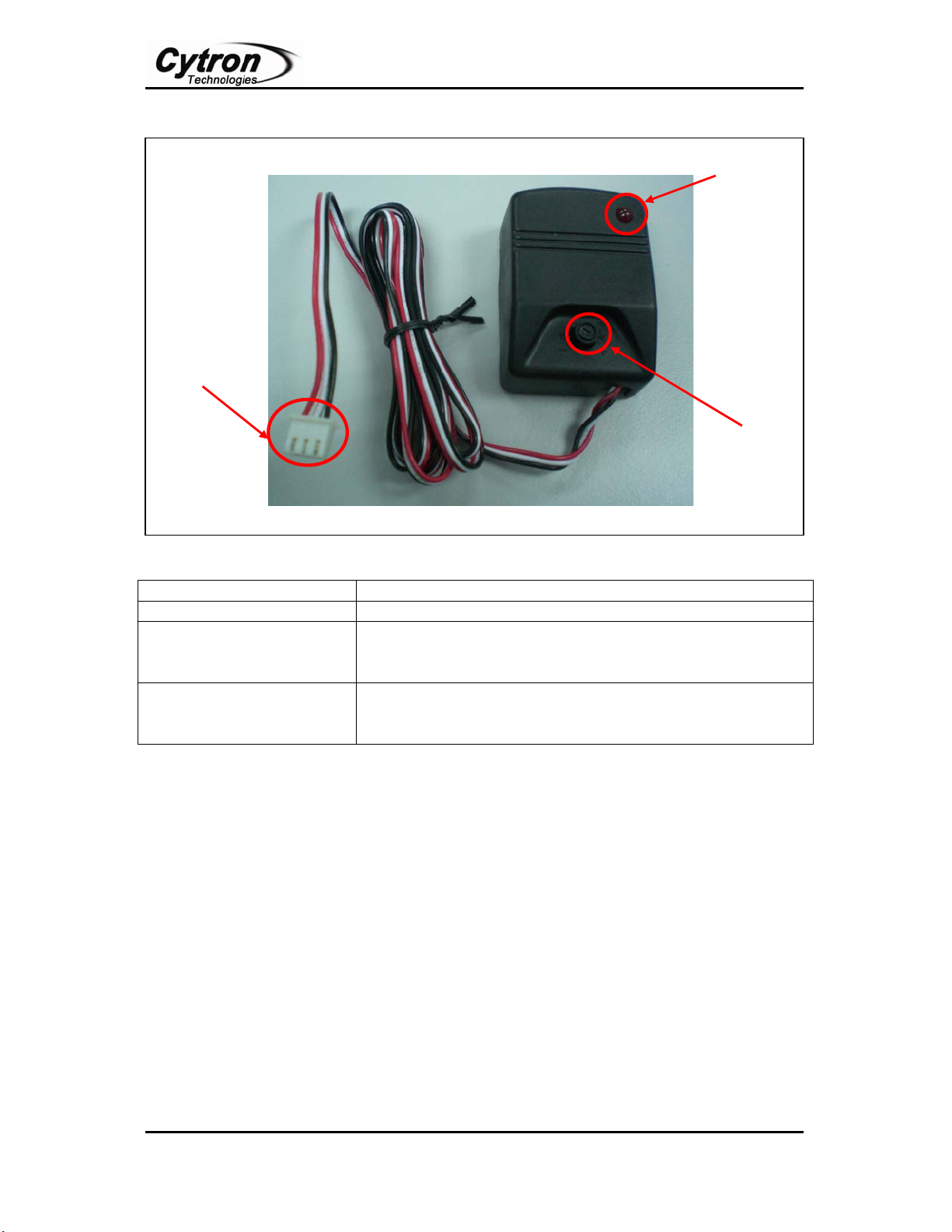
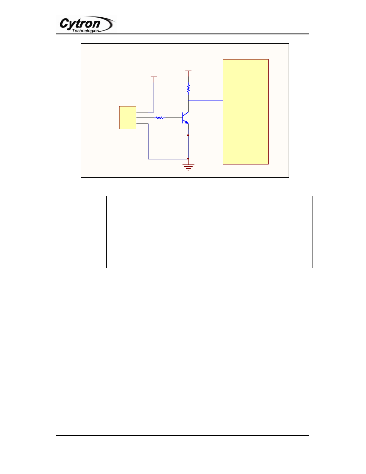
Connect the 3-pin header to your circuit so that the black colour pin connects to ground, the
red color pin connects to Vcc and the white colour pin connects to your output signal pin. The
unit output is LOW whenever there is shock detected. The output voltage of shock sensor
followed the voltage supplied to the sensor (Vcc) when there is no shock detected. Please
refer schematic in Figure 4.1 and Figure 4.2 for example application.
Figure 4.1: Example application for Shock Sensor (Without microcontroller).
Part Description
Header 3H Connects to Shock Sensor, pin 1 to GND (Black color), pin 2 to output
(White color) and pin 3 to Vcc (Red color).
Vcc Connects to Vcc (+5V to + 12V)
Buzzer Connects to buzzer (+5V to + 12V)
S1 Reset button for the circuit.
R1, R3, R5 10kΩResistor
R2, R4, R7 1kΩResistor
R6 220ΩResistor
Q1 PNP transistor ( BC557)
Q2 NPN transistor ( BC547)
Q3 NPN transistor ( 2N2222)
Table 4.1
With reference to Figure 4.1, the buzzer will be ON when there is a shock detected, and the
buzzer will only OFF when the reset button being press. The buzzer is chosen depends on the
value of Vcc. 5V buzzer will be choose when Vcc is connect to 5V whereas 12V buzzer is
chosen when Vcc is connected to 12V.

ROBOT . HEAD to TOE
Product User’s Manual – Shock Sensor
Created by Cytron Technologies Sdn. Bhd. – All Rights Reserved 5
1
2
3
Header 3
Connector to Shock Sensor
BC547
Q1
5V
1K
R1
10K
R2
VCC
Microcontroller
I/O pin
Figure 4.2: Example application for Shock Sensor (With microcontroller).
Part Description
Header 3H Connects to Shock Sensor, pin 1 to GND (Black color), pin 2 to output
(White color) and pin 3 to Vcc (Red color).
Vcc Connects to Vcc (+5V to + 12V)
R1 1kΩResistor
R2 10kΩResistor
Q1 NPN transistor ( BC547)
I/O pin of
Microcontroller
The output of the circuit need to connect to the I/O pin microcontroller
which set to ‘INPUT’ mode.
Figure 4.2
The application of shock sensor with microcontroller is shown in Figure 4.2. The function of
the transistor, Q1 is to protect the microcontroller in case the voltage supply to shock sensor
is higher than 5V. With refer to the schematic, the output signal which send to
microcontroller after Q1 will be HIGH wherever there is a shock detected. It is invert of the
original output signal of shock sensor.

ROBOT . HEAD to TOE
Product User’s Manual – Shock Sensor
Created by Cytron Technologies Sdn. Bhd. – All Rights Reserved 6
5. WARRANTY
¾Product warranty is valid for 6 months.
¾Warranty only applies to manufacturing defect.
¾Damage caused by miss-use is not covered under warranty.
¾Warranty does not cover freight cost for both ways.
Prepared by
Cytron Technologies Sdn. Bhd.
19, Jalan Kebudayaan 1A,
Taman Universiti,
81300 Skudai,
Johor, Malaysia.
Tel: +607-521 3178
Fax: +607-521 1861
URL: www.cytron.com.my
Email: [email protected]
Table of contents
Popular Accessories manuals by other brands

Emerson
Emerson Rosemount TupHFET TF396 instruction manual

Vitrolife
Vitrolife CulturePro user manual

Hytronik
Hytronik HBHC25 Installation and instruction manual

Barbarian Basketball Systems
Barbarian Basketball Systems Titanium Series Assembly instructions and owner's manual

PhiGolf
PhiGolf PHG-100 Quick manual

SIKA
SIKA INDUQ VMI 07 operating manual