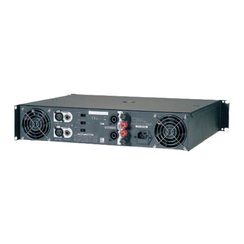
D.A.S. EP Series User manual

User's Manual
Before operating the device, please read
the “Safety precautions” section of this
manual. Retain this manual for future
reference.
EP-450 / EP-2K4 / EP-6K4 / EP-10K4 / EP-22K4
EP SERIES

CONTENTS
INSTALLATION
AMPLIFIER CONFIGURATION
INTRODUCTION
6
7
FRONT PANEL 7-8
8-9
10
REAR PANEL
3
SAFETY PRECAUTIONS
4
WARRANTY
5
DECLARATION OF CONFORMITY
12
SPECIFICATIONS
12
LINE DRAWINGS
14
ANNEX: Line connections: unbalanced and balanced
13
TROUBLESHOOTING
EP series / User’s Manual

3
EP series Safety Precautions
Keep these instructions. Read these instructions.
Heed all warnings. Follow all instructions.
The exclamation point within an equilateral triangle is intended to alert the user of important operating and maintenance (servicing)
instructions in the literature accompanying the appliance.
Where the amplifier is mounted in a rack and permanently connected to the mains, then the rack should be installed with a readily
accessible connector or an ALL POLE circuit breaker with 3mm breaking distances.
The mains switch on the amplifiers only switches one pole of the mains supply, therefore for units with a detachable cord to be fully
disconnected from the mains, the mains disconnect device (ie mains plug or mains coupler) should remain readily operable. For
units with a fixed mains lead the external all pole circuit breaker with 3mm breaking distances is the disconnect device and therefore
the installation of the amplifier shall be carried out in accordance with all the applicable installation rules.
Protect the power cord from being walked on or pinched particularly at plugs, convenience receptacles and the point where they exit
from the apparatus.
Refer all servicing to qualified service personnel. Servicing is required when the apparatus has been damaged in any way, such as if
the power-supply cord or plug is damaged, liquid has been spilled or objects have fallen into the apparatus, the apparatus has been
exposed to rain or moisture, does not operate normally, or has been dropped.
The mains circuit breaker shall remain readily accessible.
To completely disconnect this equipment from the AC mains, disconnect the power cord from the mains circuit breaker.
This unit is fitted with a 3-wire power cord. For safety reasons, THE EARTH LEAD SHOULD NOT BE DISCONNECTED UNDER ANY
CIRCUMSTANCES.
Take into account that the nominal AC voltage is the value shown in the equipment ±10% (according to IEC 60065:2001).
Unplug this apparatus during ligtning storms, earthquakes or when unused for long periods of time.
Do not install near any heat sources such as radiators, stoves or other apparatus that produce heat. Do not block any ventilation
openings, install in accordance with the manufacturer's instructions.
The cooling fans push cool air through one side and blow hot air out of the other side of the unit through the ventilating grilles.
Do not block the sides of the amplifier (i.e. in a rack with grilles). Allow an air flow gap of 5cm or more on the sides. IF THE AIR IS NOT
ALLOWED TO CIRCULATE, OVERHEATING WILL OCCUR.
Take care when mounting other equipment in the same rack.
Working temperature ranges from 15ºC to 45ºC with a maximum relative humidity of 75%.
Do not expose this device to rain or moisture. Do not use this apparatus near water (for example, swimming pools and fountains). Do
not place any objects containing liquids, such as bottles or glasses, on the top of the unit. Do not splash liquids on the unit. IP-20
equipment. Clean only with a dry cloth. Do not use any solvent based cleaners.
This symbol on the product indicates that this product should not be treated as household waste. Instead it shall be handed over to
the appicable collection point for the recycling of electrical and electronic equipment.
Only use attachments/accessories specified by the manufacturer. Use only with the cart, tripod, bracket or table specified by the
manufacturer, or sold with the apparatus. When a cart is used, use caution when moving the cart/apparatus combination to avoid
injury from a tip over.
WARNING: To prevent injury, this apparatus must be securely attached to the rack in accordance with the installation instructions.
The connected outer wiring to these terminals requires of its installation by an instructed person and the use of a flexible cable already
prepared.
The lightning flash with arrowhead symbol within an equilateral triangle is intended to alert the user to the presence if uninsulated
“dangerous voltage”. To reduce the risk of electric shock do not remove the cover. No user serviceable parts inside.
WARNING: Apparatus with CLASS I construction shall be connected to a MAINS socket outlet with a protective earthing connection.
EP series / User’s Manual

WARRANTY
All our products are warrantied against any manufacturing
defect for a period of 36 months from date of purchase.
The warranty excludes damage from incorrect use of the
product.
All warranty repairs must be exclusively undertaken by the
factory or any of its authorised service centers.
To claim a warranty repair, do not open or intend to repair
the product.
All the details related to the warranty (such as extended
warranties) can be found in the SUPPORT section on our
website: www.dasaudio.com
4EP series / User’s Manual

5
DECLARATION OF CONFORMITY
DAS Audio Group, S.L.
C/ Islas Baleares, 24 - 46988 - Pol. Fuente del Jarro - Valencia. España
(Spain).
Declares that EP series:
In accordance with Harmonized European Norms:
EN 62368-1:2014.- Audio/video, information and communication
technology equipment - Part 1: Safety requirements.
EN 55032:2012.- Electromagnetic compatibility of multimedia
equipment. Emission requirements.
EN 55103-2:2009.- Electromagnetic compatibility. Product family
standard for audio, video, audio-visual and entertainment lighting
control apparatus for professional use. Part 2:Immunity.
EN 50581:2012.- Technical documentation for the assessment of
electrical and electronic products with respect to the restriction of
hazardous substances.
Abide by essential objectives relating Directives:
Low Voltage Directive 2014/35/UE
Electromagnetic compatibility Directive EMC 2014/30/UE
RoHS Directive 2011/65/UE
RAEE Directive (WEEE) 2012/19/UE
EP series / User’s Manual

INSTALLATION
Unpacking
Carefully open the shipping carton box and check for any
noticeable damage. Every amplifier has been QC tested
and inspected before leaving the factory. If any damage
may had happened during transportation notify the
incidence to the shipping company immediately. Keep
the carton box in case you need to ship the amplifier to an
authorized service center.
Rack Mounting
Free airflow, front to rear, of the amplifier unit must be
allowed. Therefore, no doors or rack lids should be
mounted in front of or behind the amplifiers in order to
not block the airflow necessary to cool the units.
Amplifiers may be installed stacked directly one on top of
each other, but the ideal configuration would be spacing
them vertically 1 rack unit.
It is recommended to assembly the rear brackets
provided with the units when fixing them to a rack:
Cooling
The amplifier uses a forced air cooling system with front to
rear airflow in order to maintain a controlled operation
temperature.
The cooling fans suck cool air in through the front and
blow hot air out at the rear of the unit through the
ventilating grills. The front and rear of the amplifier should
have free exposure to the air (i.e. in a rack leave the front &
rear doors off), with 2cm air gap at the sides.
It is also very important to keep clean the dust filters
located behind the detachable front panel in order to
ensure always maximum air flow.
The filter behind the air intake apertures on the front of
your amplifier should be cleaned or replaced periodically,
e.g. 12-24 months. (Filters in amplifiers located in more
'dirty' atmospheres may require more f requent
maintenance).
The filter should be 'dry' cleaned, using a vacuum cleaner
preferably. Running the unit without a filter is not
Operating Voltage
The label placed close to the mains cable at the rear
amplifier panel indicates the nominal operating voltage
of the unit. Be sure of the nominal voltage required by the
amplifier before connecting it to the mains.
In case the power connector supplied with the power cord
is not valid for you area / region it would need to be
removed and replaced by a convenient one wired as
follows:
Rear mounting brackets and hardware provided
Insert the Screw + Washer and fix the bracket to the rear
panel for permanent installation
Use the Spacer for non permanent installation
6EP series / User’s Manual
BLACK or BROWN
WHITE or BLUE
GREEN or GREEN/YELLOW
LIVE
NEUTRAL
EARTH (GROUND)
Once a suitable AC supply is connected to the unit, the
amplifier can be turned on using the front panel power
switch. The amplif ier will start a short auto-check
sequence:
- Power led will lit in green.
- The fans will blow at the highest speed before dropping
to idle state.
- Mute leds will indicate that all output channels are
muted during the test. After 3 seconds channels will be
unmuted.
The inrush current is controlled during the auto-check
sequence enabling multiple amplifiers to be turned on at
the same time.
2x
Power cables
115V areas
Use standard 15A Edison plug for models EP-2K4 and
EP-6K4. One 20A circuit per amplifier.
Use Nema L5-30 Twist lock plug for models EP-10K4 and
EP-22K4. One 30A circuit per amplifier.
230V areas
Use in all cases standard 16A Schuko plug.

7
General
Thank you for purchasing DAS EP series power amplifiers. They have been designed with the lastest and most advanced
Class D technology. As a result, a family of multi channel high power, high efficiency amplifiers has been created for
medium/big sized professional applications.
Features
- 4 channel high power amplifiers
- Class D, switching power supply
- Integrated voltage limiters, adjustable by the user
- Independent Volume controls per channel
- Power On led and dual color Signal/Clip leds per ouput channel
- Thermal protection
- Over current protection
- Built in DC protection
- Short Circuit protection
- Stereo (low impedance) and Bridge (high impedance) modes
- Speakon NL4 connectors
FRONT PANEL
INTRODUCTION
A) Power Switch
Turns the amplifier on (“I” position) and off (“0” position).
When the amplifier is turned on the “power” LED will light
up in green.
B) Channel Gain Controls
Four level potentiometers are located at the front panel
providing individual channel attenuation. Level range
varies from - 50dB to 0dB. The 12 o´clock position equals
to -25dB attenuation.
C) Front Covers with dust filters.
there are two front covers located, each one located on
one side of the front panel. To loose the front cover use the
M3 thumb screws located underneath the amplif ier
handles. This allows removal of the dust filters for cleaning
and maintenance.
D) Mute Leds
When the amplifier is turned on, mute leds will appear
active (red) while the amplifier is doing an auto test. After
three seconds the MUTE leds will be deactivated.
E) Bride Mode
When active (rear panel dips), the led will light up in green.
Remember not to use 4ohm loads in Bridge mode.
F) Temperature and Load indicators
G) Channel meters
Each output channel is equipped with a signal meter:
EP series / User’s Manual
A
B
C
DE
Temp Warning (Flashing Yellow)
Temp Mute (Permanent Yellow)
Output Muted (Permanent Yellow)
Load fault
F
Hi-Z/open load detected (Yellow)
Amp Peak limiter active (Red)
Current Peak limiter active (flashing Orange)
Very Low impedance / Short circuit (Permanent Orange + MUTE)
All EP series models are equipped with protection circuits
that detect continuous very high frequency content in the
input signal. The detection starts from 10 kHz on. If these
type of signals are detected in the amplifier, the output
will be muted for 6 seconds before re-measuring.
Once no continuing very high frequency signal is
detected, the output un-mutes and returns to normal
state.
This feature recognizes that continuous full-scale VHF
signals do not appear in “natural” sources such as music.
Any such signals can therefore be considered as a fault
when present. VHF protection is essential in avoiding
damage to high frequency drivers.
The VHF protection is NOT a limiter and does not alter the
amplifier’s frequency response. It is implemented solely
to detect continuous VHF content. The amplif ier will
always pass VHF peaks at full power, with no effect on
musical “transients”.
G

8
REAR PANEL
A) Mains input
B) Analogue balanced audio inputs
Four XLR input connectors located at the rear panel allow
injecting signal to the different channels of the amplifier.
C) Amplifier outputs
Four Neutrik NL4 output connectors located at the rear
panel permit the connection of the amplier channels to
the speaker systems. The amplifier outputs are named CH
A, CH B, CH C and CH D.
NL4 connector for outputs B and D include 2 active
connecting pins, +/-1.
NL4 connectors for outputs A and C include 4 active
connecting pins, +/-1 and +/2. By doing this the user may
have all the four output channels connected to 2 cables.
When using channels in bridge mode the speaker
systems must be connected to CH A or CH C using the pins
+1/-2.
D) DIP Switches
different parameters of the amplifier can be configured at
the rear panel with the mini DIP switches:
EP series / User’s Manual
AB
200 -24 0V 5 0-6 0H z: 250 0W
CDE
Amp Gain Bridge mode
Peak limiters
Peak limiters mode
E) Analogue balanced audio outputs.
Two XLR output connectors located at the rear panel
allowing having a copy of inputs A & C.

I
0
INPU T A
STERE O
PARALLE L
BRIDG E
C&D
A&B
Output:A
Output:A
1+:HOT
1- :COLD
Output:B
Output:B
1+:HOT
1- :COLD
Output:A
1+:HOT
2- :COLD
[BRIDGE]
Input:A,
Output:C
1+:HOT
1- :COLD
Output:D
1+:HOT
1- :COLD
Output:C Output:D
INPU T BINPU T CINP UT D
Output:C
1+:HOT
2- :COLD
[BRIDGE]
Input:C,
2Ω
2Ω
0.775V 0V 32dB
100VAC-240VAC
50Hz-60Hz
PUSH PU SH PUSH
PUSH
Input sensivity choice;
The input sensivity choice of this device is 0.775V( factory seng ),1V,32dB
0.775V
1V
32dB
Input mode choice
Stereo mode( factory mode)
When set as the figure, channels A and B are in stereo mode, set
each channel volume directly. Operaon of Channels C and D
will be the same;
Parallel mode
When set as the figure, channels A and B are in parallel mode, input
signal into channel A , then both, A and B channels use the same signal
Set each channel volume directly. Operaon of
Channels C and Channel D will be the same.
Bridge mode
When set as the figure, channels A and B are in bridge mode, input
signal into channel A, channels A and B will operate as a mono
output, volume control of Channel A will manage both channels. Operaon of
Channels C and Channel D will be the same.
STEREO
PARALLEL
BRIDGE
STEREO
PARALLEL
BRIDGE
STEREO
PARALLEL
BRIDGE
FRONT PANEL
A) Level control
Four level potentiometers are located at the front panel
providing individual channel attenuation. Level range
varies from - 50dB to 0dB. The 12 o´clock position equals
to -25dB attenuation
B) Power ON Indicator
This LED lights when the mains switch is pressed. If it does
not light up, the unit is not connected to the mains or the
mains fuse has blown.
C) Signal indicator
This LED lights up if signal is detected at the amplier´s
output channel. The indicator goes off when no signal or
when a protective circuit has been activated in the
amplifier.
D) Limit
This LED lights up if the limiter threshold has been
reached and the amplifier is being operated at the clip
level. When the LED flashes permanently the volume of
the input audio source should be reduced or the gain
control of the amplif ier´s channel turned counter
clockwise.
E) Power Switch
The unit is switched on by the use of the power switch.
Loudspeaker outputs are switched on via delayed relays in
order to avoid audible transients.
A
BC
E
D
REAR PANEL
9
EP series / User’s Manual

10 EP series / User’s Manual
EP-10K4
EP-10K4
150 V
300 V
101 V 101 V
202 V 202 V
195 V
195 V
121 V
242 V
83 V 83 V
166 V 166 V
170 V
170 V
101 V
202 V
70 V 70 V
140 V 140 V
140 V
140 V
83 V
166 V
56 V 56 V
112 V 112 V
116 V
116 V
70 V
140 V
47 V 47 V
94 V 94 V
100 V
100 V
56 V
112 V
38 V 38 V
76 V 76 V
80 V
80 V
47 V
94 V
n/a n/a
n/a n/a
66 V
66 V
38 V
76 V
n/a n/a
n/a n/a
54 V
54 V
EP-6K4
EP-6K4
EP-2K4
EP-2K4
EP-22K4
EP-22K4
AMPLIFIER CONFIGURATION
All EP series models include at the rear panel a group of
mini dips to configure different settings of the units.
These are the parameters accessible via rear panel of the
units:
- Amplifier GAIN (dB). By default is set to 35dB.
- Bridge or Stereo mode. By default is set to stereo mode.
- Maximum voltage available per output channel. This is
basically a limiter that allows the end user to reduce the
voltage produced by the amplifier to match the power
capacity of the audio systems. By default the amplifier is
set to its maximum capability.
- Hard or Soft limiting mode. When hard mode is enabled
the attack time of the limiter is shorter and allows less
peaks to be driven to the load.
Gain
Globally affects all channels. From + 23 dB to + 44 dB in
3dB steps.
Bridge
Switches the channel pairs into bridge mode. Valid for
channels A+B and C+D.
Voltage Limiters
Adjust (per channel) the maximum value of the desired
peak voltage accordingly to the audio system´s power
handling.
Rear mini DIPs detail
VOLTAGE PEAK LIMITERS
Maximum voltage (per channel) Stereo mode
Maximum voltage (per channel) Bridge mode
Input and Output connectors
All EP series models are equipped with 4x XLR input
connectors (one per amplifer channel). All models include
2x XLR output (loop thru of input channels A and C)
connectors are also available for daisy chaining multiple
amplifier channels using the same audio signal.
All EP series models are equipped with 4x NL4FC Speakon
Output connectors (Speaker Outputs), one per amplifier
channel.
Two amplified channels can be connected from a single
NL4FC connector (see figure below, CH A and B):
CH A and B
+-1 / +-2
CH C
+-1
CH D
+-1
When using a bridge configuration use pins +1 and -2 of
the NL4 connector in your cable.

Cables and Output Connectors
Use one of these three options when connecting your
cable to the amplifier output channel connector:
Only one channel driven
per output cable
Balanced Input Connections
All EP series models are equipped with 4x XLR balanced
input connectors, one per amplifier channel. The XLR
input connectors are electronically balanced and wired
according to the IEC268 standard (pin 2 = +). XLR cable
connectors should be wired as follows:
Pin 1 Ground/Shield
Pin 2 Hot (+)
Pin 3 Cold (-)
Unbalanced Input Connections
These type of connection is not recommended for
professional audio applications as it may cause noise in
the installation.
Cables and Output Connectors
Use one of these three options when connecting your
cable to the amplifier channels:
Two channels driven per
output cable (stereo mode)
Two channels driven per
output cable (bridge mode)
The outputs on all EP series models produce high voltage.
Do not connect or disconnect the loudspeaker cables
while the amplifier is working. Never operate an amplifier
with any portion of bare loudspeaker cable exposed.
11
EP series / User’s Manual
WARNING:
Minimum nominal impedance per channel 4ohm

12 EP series / User’s Manual
SPECIFICATIONS
EP-2K4EP-450 EP-6K4 EP-10K4 EP-22K4
4 x 600W
4 x 600W
15A15A
88 x 485 x 440 mm
50 x 489 x 248 mm
190 x 571 x 508 mm101 x 546 x 317,5 mm 177,8 x 660 x 622,3 mm
7.5 x 22.5 x 20 in
4 x 21.5 x 12.5 in 7 x 26 x 24.5 in
3.5 x 19 x 17.3 in
2 x 19.25 x 9.75 in
14 kg (30.8 lb)
4,5 kg (10 lb)
14 kg (31 lb)
6 kg (13.2 lb)
14.5 kg (31.9 lb)
14 kg (31 lb)
15.5 kg (34.1 lb)
15,8 kg (35 lb)
19.5 kg (42.9 lb)
20,86 kg (46lb)
4 4
2 x 1200W
-
4 x 1250W 4 x 2100W
15A
2 x 4200W
4 x 4650W
2 x 9500W
4 x 300W
4 x 400W 4 x 625W
15A
2 x 2500W
4 x 1350W 4 x 2500W
All specifications are subject to change without prior notice.
Output Power Ratings
Power 8 Ohms, all Channels Driven
Power 8 Ohms, two Channels Bridged
Power 4 Ohms, all Channels Driven
Electronics and Connectors
Dimensions - Weight
Dimensions ( H x W x D )
Net Weight
Shipping
Carton Dimensions ( H x W x D )
Shipping Weight
Amplifier Channels
Output Circuitry
Frequency Response
Voltage Gain
Controls
Cooling
Amplifier Protections
LED Indicators
Audio Signal Input Connectors
Speaker Output Connectors
AC Power Requirements, 115A
4
Switched Amplification
10 Hz - 30 kHz (0/-0.5dB)
23 - 44 dB (Rear DIPs adjustable)0.775V / 1V / 32 dB
Power On/Off, Gain Pots, Rear DIP SwitchesPower On/Off, Gain Pots
Front to Back
Thermal, Overload, Short Circuit, Over Current
Independent Channel Meters, CLIP/VPL, Mute, VHF, Temp, On
4 x Balanced Neutrik XLR
4 x Neutrik NL4
4 4
30A
485
445
467
76
88
505
440
485
445
467
76
88
88 x 485 x 440 mm
3.5 x 19 x 17.3 in
88 x 485 x 440 mm
3.5 x 19 x 17.3 in
88 x 485 x 505 mm
3.5 x 19 x 19.9 in
LINE DRAWINGS
EP-2K4 / 6K4 / 10K4
EP-22K4
I
0
INPUT A
STEREO
PARALLEL
BRIDGE
C&D
A&B
Output:A
Output:A
1+:HOT
1- :COLD
Output:B
Output:B
1+:HOT
1- :COLD
Output:A
1+:HOT
2- :COLD
[BRIDGE]
Input:A,
Output:C
1+:HOT
1- :COLD
Output:D
1+:HOT
1- :COLD
Output:C Output:D
INPUT BINPUT CINPUT D
Output:C
1+:HOT
2- :COLD
[BRIDGE]
Input:C,
2Ω
2Ω
0.775V 0V 32dB
100VAC-240VAC
50Hz-60Hz
PUSH PUSH PUSH
PUSH
248 483
44
EP-450
7.5 x 22.5 x 20 in 7.5 x 22.5 x 20 in
190 x 571 x 508 mm
190 x 571 x 508 mm

13
TROUBLESHOOTING
No sound from the unit
Full power cannot be obtained.
Sound is distorted.
Hum or buzz when a mixer is connected to the
unit.
Hum or buzz when using lighting controls in
the same building.
Low sound.
The MUTE led and the Temp Led are
indicating protection.
1 - The unit has activated the thermal
protection.
1 - Lower the input level and make sure the
amplifier is being cooled correctly. Check that
the fan is working and be sure that all the air
inlets/outlets are not blocked.
1-The console probably has unbalanced
outputs. You may be using an incorrect
unbalanced to balanced cable.
2 - The mixer and the powered speaker are
not plugged into the same mains outlet.
3 - The audio signal cable is too long or
too close to an AC cable.
1-The audio signal cable is too long or too
close to the lighting cable.
2 - On a sound system with three phase AC,
the lighting equipment and the unit are
connected to the same phase.
1 -The audio signal cable is defective.
2-The Level controls are not at maximum
position.
3 - Low input signal level.
4 - Using speakers with transformer in stero
mode.
1- Move the audio signal cable away from
lighting cables.Try to find out at what point
the noise is leaking into the system.
2 - Connect the sound system to a different
phase than the lights. You may need the help
of an electrician.
1- Check cabling and replace them.
2 - Turn up level controls of the output
channles.
3 - Turn up the level from the source.
4 - Change the amplifier´s mode from Stereo
to Bridge (100/70V).
1-Read the appendix of this manual to make a
correct unbalanced to balanced cable.
2 - Connect the mixer and the unit to the same
mains outlet.
3 - Use a cable that is as short as possible
and/or move the audio signal cable away from
mains cables.
1-The mixer or signal source is distorting.
2 - The output level from the mixer is too high.
3 - Amplifier clip shown in the channel.
1-Turn down the mixer´s output and check no
channels are distorting.
2 -Turn down the mixer´s output.
3 - Turn down input gain controls or lower
input signal level.
1 - The signal source does not have enough
ouput level and / or the amplifier GAIN is set to
a low value.
2 - Input gain controls are at very low volume.
1 - Use balanced outputs of a mixer.
Rise master ouput volume of the source.
Use a professional sound mixer providing
enough ouput voltage.
Set the amplifier gain to a higher value.
2 - Set up level controls at higher positions.
1 - The signal source is sending no signal.
2- Input gain controls are at minimum
position.
3 - Defective signal cables.
4 - Amplifier not plugged.
5 - Thermal protection activated.
1 - Check that the source is not muted and is
sending signal to the unit.
2 - Check input gain controls. Put them at
maximum level.
3 - Check that the cable from the source to the
unit is connected correctly. Replace the cable if
defective.
4 - Check the connections.
5 - Lower de input signal level and double
check that the amplifier fans are working
properly.
EP series / User’s Manual
PROBLEM CAUSE SOLUTION

14
There are two basic ways to transport an audio signal with microphone or line level:
Unbalanced line: Utilising a two conductor cable, it transports the signal as the voltage between them.
Electromagnetic interference can get added to the signal as undesired noise. Connectors that carry
unbalanced signals have two pins, such as RCA (Phono) and ¼” (6.35mm, often referred to as jack) mono. 3 pin
connector such as XLR (Cannon) may also carry unbalanced signals if one of the pins is unused.
Balanced line: Utilising a three conductor cable, one of them acts as a shield against electromagnetic
noise and is the ground conductor. The other two have the same voltage with respect to the ground
conductor but with opposite signs. The noise that cannot be rejected by the shield affects both signal
conductors in the same way. At the device’s input the two signals get summed with opposite sign, so that
noise is cancelled out while the programme signal doubles in level. Most professional audio devices use
balanced inputs and outputs. Connectors that can carry balanced signal have three pins, such as XLR
(Cannon) and ¼” (6.35mm) stereo.
The graphs that follow show the recommended connection with different types of connectors to
balanced processor or amplifier inputs. The connectors on the left-hand side come from a signal source, and
the ones on the right hand side go to the inputs of the processor or amplifier. Note that on the unbalanced
connectors on the left-hand side, two terminals are joined inside the connector. If hum occurs with balanced
to balanced connections, try disconnecting the sleeve (ground) on the input connector. Note that the
illustrations show what should be connected to what, but that pin locations on an actual XLR connector are
different. Also, pin 2 hot is assumed on XLR connectors.
ANNEX : Line connections: unbalanced and balanced
EP series / User’s Manual

UM_EP_01_EN
www.dasaudio.com
DAS Audio Group, S.L.
C/. Islas Baleares, 24
46988 Fuente del Jarro
Valencia, SPAIN
Tel. +34 96 134 0860
DAS Audio of America, INC.
6900 NW 52th Street
Miami, FL. 33166 - U.S.A.
TOLL FREE: 1 888 DAS 4 USA
DAS Audio Asia PTE. LTD.
3 Temasek Avenue, Centennial
Tower #34-36
Singapore 039190
Tel. +65 6549 7760
DAS do Brasil LTDA.
Rua Dos Andradas, 382 SL
Santa Efigênia, São Paulo
Brasil. CEP: 01208-000
Tel. +551133330764
DAS Audio Gmbh
Mülheimer Str. 48
53840 Troisdorf
Germany
Tel. +49 2241 945880
This manual suits for next models
5
Table of contents
Other D.A.S. Amplifier manuals
D.A.S.
D.A.S. CSA series User manual
D.A.S.
D.A.S. DX-80 User manual
D.A.S.
D.A.S. INTEGRAL-WA4 User manual
D.A.S.
D.A.S. H-1500 User manual
D.A.S.
D.A.S. PA Series User manual

D.A.S.
D.A.S. PA-500 User manual

D.A.S.
D.A.S. ps-200 User manual

D.A.S.
D.A.S. T series User manual
D.A.S.
D.A.S. DXi Series User manual
D.A.S.
D.A.S. D-100 User manual

