d & b audiotechnik A1 Mainframe F-Series User manual

A1 Mainframe
F-Series, M2, M1220
User Manual
A1 Mainframe, F-series, M2, M1220 User Manual
Version 4.0 E, 02/2001, D2100.E.04
© d&b audio echnik 1995-2001; all righ s reserved.
The informa ion presen ed in his documen is, o he bes of our
knowledge, correc . We will however no be held responsible for
he consequences of any errors or omissions.
Technical specifica ions, weigh s and dimensions should always be
confirmed wi h d&b audio echnik AG prior o inclusion in any addi-
ional documen a ion.
d&b audio echnik AG
Eugen-Adolff-S rasse 134, D-71522 Backnang
Telephone +49-7191-9669-0, Fax +49-7191-95 00 00
WARNING!
CAUTION!
IMPORTANT!
References in the manual
This refers to a potentially
dangerous situation which may
lead to personal injury.
This refers to a potentially
dangerous situation which may
lead to damage to the
equipment.
This refers to a situation which
may cause the equipment to
malfunction.
Symbols on the equipment
Please refer to the information in
the operating manual.
WARN NG! Dangerous voltage!

WARNING!
CAUTION!
(4.0 E) Safety precautions
Safety precautions
Before you use our products, read the manual
carefully and observe all the safety precautions.
They will protect you and help to avoid equipment
failures. Keep this manual in a safe place so that it is
available for future reference.
f you supply d&b products, please draw the
attention of your customers to these safety
guidelines. Enclose the relevant manuals with the
systems. f you require additional manuals for this
purpose, you can order them from d&b (order form
on the last page).
nformation regarding use of the A1 mainframe
The mainframe complies wi h he elec romagne ic compa ibili y
requiremen s of EN 50082-1 - residen ial, business and commercial
areas.
Acous ic in erference and malfunc ions may occur if he uni is
opera ed in he immedia e vicini y of high-frequency ransmi ers
(e.g. wireless microphones, mobile phones, e c.). Damage o he
mainframe is unlikely, bu canno be excluded.
To mee he EMC requiremen s, use only shielded cables wi h
properly conneced plugs for all signal erminals (INPUT, INPUT
LINK, MONO OUT).
The following informa ion is in ended o preven fires and possible
elec ric shocks:
The mainframe is a pro ec ive class 1 uni . Make sure ha he ear h
(ground) con ac is a ached when he uni is in opera ion. A missing
ear h (ground) con ac may lead o dangerous vol ages in he
housing and con rols.
To reduce he possibili y of audible hum he mainframe signal
ground (XLR pin 1) o ear h (ground) connec ion has a high
impedance. I will preven he uni from s a ic charge bu any
vol age applied o signal ground will pass hrough all connec ors.
To preven elec ric shock, make sure ha all devices in he signal
pa h are grounded properly.
Never connec an amplifier ou pu pin o any o her in- or ou pu
connec or pin or ear h (ground). This migh damage he mainframe
or lead o elec ric shock.
Lay all cables o and from he uni so ha hey canno be crushed
by vehicles or o her equipmen and ha no-one can s ep on hem.
Keep dus , mois ure, wa er or o her liquids well away from he uni .
Never opera e he uni when i is open.
Always disconnec he mains power supply when replacing a
defec ive fuse. Only use he ype of fuse lis ed in he specifica ions.

WARNING!
WARNING!
Safety precautions (4.0E)
Only carry ou work specified in his manual and always disconnec
he mains power supply.
All o her work should be performed by rained service s aff,
especially in he following cases:
- Mains power cable or plug has been damaged
- Objec s or liquids have en ered he uni
- The uni is no opera ing normally
- The uni was dropped or he housing is damaged
nformation regarding use of loudspeakers
Never s and in he immedia e vicini y of loudspeakers driven a a
high level. Professional loudspeaker sys ems are capable of causing
a sound pressure level de rimen al o human heal h. Seemingly
non-cri ical sound levels (from approx. 95 dB SPL) can cause
hearing damage if people are exposed o i over a long period.
In order o preven acciden s when deploying loudspeakers on he
ground or when flown, please ake no e of he following:
When se ing up he loudspeakers or loudspeaker s ands, make
sure hey are sanding on a firm surface. If you place several
sys ems on op of one ano her, use s raps o secure hem agains
movemen .
Only use accessories which have been es ed and approved by
d&b for assembly and mobile deploymen . Pay a en ion o he
correc applica ion and maximum loading capaci y of he
accessories as specified in our Rigging Accessories Manual.
Ensure ha all addi ional hardware, fixings and fas eners used for
ins alla ion or mobile deploymen are of an appropria e size and
load safe y fac or. Pay a en ion o he manufac urers ins ruc ions
and o he relevan safe y guidelines.
Regularly check he loudspeaker housings and accessories for
visible signs of wear and ear, and replace hem when necessary.
Regularly check all load bearing bol s in he moun ing devices.

CAUTION!
(4.0 E) Safety precautions
Only use loudspeakers in he F-Series and he M2 and M1220
moni ors wi h he A1 mainframe fi ed wi h he correc con roller
modules. The con oller moni ors cone excursion and voice coil
empera ure of he drivers. When loudspeakers are opera ed
wi hou he correc con roller, in addi ion o losses in one, here is
a risk of damage o he componen s. Any defec s arising from
opera ion o her han hose specified in his manual will be excluded
from any warran y claims.
Loudspeakers produce a s a ic magne ic field even if hey are no
connec ed or are no in use. Therefore make sure when erec ing
and ranspor ing loudspeakers ha hey are nowhere near
equipmen and objec s which may be impaired or damaged by an
ex ernal magne ic field. Generally speaking, a dis ance of 0.5 m
(1.5 f ) from magne ic da a carriers (floppy disks, audio and video
apes, bank cards, e c.) is sufficien ; a dis ance of more han 1 m
(3 f ) may be necessary wi h compu er and video moni ors.

A1 mainframe front and rear views
A1
GR LO
ISP
GR HI
OV LO
OV HI
CUT
MON
LFC
MUTE
12 2 0 - C O
0
-6
-12
-18
0
+3-3
dB HI dB
ID
OFF
ON
REM
PWR
TEMP
REM
PROT
LOCK
LO HI
INPUT
INPUT LINK
PUSH
REMOTE
CONTROL
FUSE T2A
220V-240V
∼
50-60 Hz
OVER
VOLTAGE
FUSE T8A FAIL
FAIL
PIN ASSIGNMENT
OUTPUT 2
OUTPUT 1
A LOW OUT +
B LOW OUT -
C SPEAKER ID
D SPEAKER ID
E SENSE DRIVE +
F SENSE DRIVE -
G HIGH OUT +
H HIGH OUT -
1220
Configuration switches
These switches depend on the
type of loudspeaker. They are
described individually for each system
in the section "Loudspeakers".
Displays and controls of
controller modules
These elements are common to all
modules. They are described in the
section "Controller modules".
Displays and controls
of mainframe
These elements are described in
the section "A1 mainframe".
Output connectors
These elements are described
individually for each system
in the section "Loudspeakers".
Input connectors
These elements are described in
the section "A1 mainframe".

(4.0 E) Contents
Contents
Safety precautions
1. ntroduction................................................... 1-1
1.1. Sys em concep ......................................................................... 1-1
1.2. d&b ac ive sys ems design...................................................... 1-2
1.3. Block diagram ..........................................................................1-2
2. A1 mainframe ............................................... 2-1
2.1. Fea ures..................................................................................... 2-1
2.1.1. A1 power amplifiers ................................................................2-1
2.1.2. SenseDrive ................................................................................2-1
2.1.3. SpeakerID ................................................................................. 2-2
2.1.4. Fan.............................................................................................2-2
2.1.5. Mains overvol age pro ec ion................................................ 2-3
2.1.6. Mains inrush curren limi er .................................................... 2-3
2.1.7. Fuses ..........................................................................................2-3
2.1.8. Remo e con rol & moni oring ................................................ 2-3
2.2. A1 con rols & indica ors.......................................................... 2-5
2.3. Connec ions ..............................................................................2-6
2.4. Mainframe ins alla ion ............................................................2-7
2.5. Power consump ion and power loss...................................... 2-8
2.6. Technical specifica ions ...........................................................2-9
3. Controller modules........................................ 3-1
3.1. Fea ures..................................................................................... 3-1
3.2. Con rols & indica ors............................................................... 3-2
3.3. Module exchange and replacemen ...................................... 3-3
4. Loudspeaker systems .................................... 4-1
4.1. Connec ions ..............................................................................4-2
4.2. Da a shee s for he loudspeakers .......................................... 4-3
F1220
F1222
M1220
M2
F2
B1-SUB
B2-SUB
5. System operation .......................................... 5-1
5.1. Se ing up/s acking he loudspeakers ................................... 5-1
5.1.1. Ver ical coverage .................................................................... 5-1
5.1.2. Arraying mid/high cabine s ................................................... 5-1
5.1.3. S acking subwoofers................................................................ 5-2
5.2. Wiring ....................................................................................... 5-3
5.3. Level se ing for mixed sys ems..............................................5-4
6. Troubleshooting ............................................ 6-1
7. Publications list.............................................. 7-1
8. EU declaration of conformity (CE symbol) ..... 8-1


(4.0 E) 1-1
1. Introduction
This user manual describes he facili ies, func ions and opera ion of
d&b ac ive con roller loudspeaker sys ems and covers he opera i-
on of he A1 mainframe, con roller modules and loudspeakers used
in hese sys ems.
d&b publishes addi ional applica ion and echnical informa ion no -
es (TI). A d&b publica ions lis and order form is appended o his
manual and we will gladly send you any of he lis ed publica ions
on reques .
This user manual should provide he informa ion you need in order
o ge he bes performance ou of he sysem. If you have any
commen s on he informa ion presen ed, or feel ha some hing is
inadequa ely explained or no covered, hen please ell us using
he commen s sec ion of he publica ion order form.
1.1. System concept
All d&b loudspeaker sys ems are designed o mee he following
cri eria :
- Consis en neu ral sound over he full working dynamic range
- Ease of opera ion
- Simple se up and wiring
- Safe and reliable opera ion
- Compac design
In order o sa isfy hese demands d&b developed a comple e
sys em concep incorpora ing he loudspeaker, he loudspeaker
specific con rol elec ronics ( he con roller) and he power amplifier.
Fundamen al o he performance of he loudspeaker is he care
aken in he developmen of individual componen s resul ing in well
con rolled dispersion, high efficiency and excellen dynamic
response.
The con roller crea es he op imum mix of ou pu level capabili y,
opera ing reliabili y and longevi y, and pure sound quali y.
Pro ec ive circui s con inuously model he loudspeaker load hrough
simula ion of cone displacemen and voice coil empera ure
ensuring signal level is only reduced when necessary o preven
driver damage. No signal compression akes place wi hin he
sys ems normal opera ing range and here is no dynamic
manipula ion of sys em frequency response enabling mos
applica ions and acous ic environmen s o require no addi ional
signal processing.
The power amplifier and con rol for each loudspeaker are housed
wi hin he A1 and P1200A mainframes or he E-PAC power
amplifier con roller. All sys ems are compa ible, easily combined
and complemen ary, and can be accessed using he d&b remo e
con rol sys em o allow overview and con rol over he mos
complex applica ions.
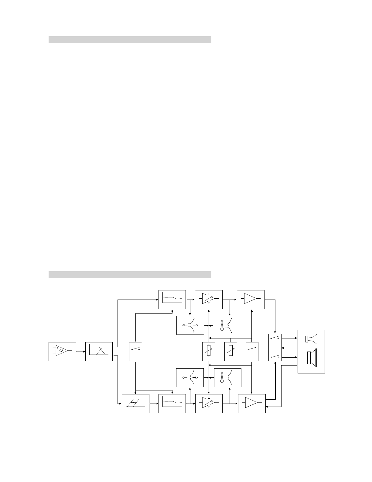
Block diagram - full range active system
Highpass
switchable
2-way box
with Speaker ID
and SenseDrive
Configuration
Level
ute
Displacement
Temperature
Input Stage
HF-Protect
EQ VCA
Power Amplifier
Cross Over
EQ VCA
Power Amplifier
HF Level
ID
Sense
Drive
Displacement
Temperature
1-2 A1 User Manual
1.2. d&b active systems design
Their are wo ypes of d&b ac ive loudspeaker sys em - ac ive sub-
woofers and full range, 2 way, ac ive loudspeakers. Each ype of
ac ive sys em is driven by an A1 mainframe fi ed wi h a single,
loudspeaker specific con roller module.
The differen loudspeaker con roller modules house he signal pro-
cessing elec ronics, connec ors, con rols & indica ors appropria e o
he differen ypes of loudspeaker.
As well as he con roller module, he A1 mainframe houses wo se-
para e power amplifiers - a 1200 W / 4 Ohm low frequency am-
plifier and a 350 W / 4 Ohm high frequency amplifier. In he case
of he full range 1220 Sys em, a single A1 fi ed wi h a 1220 con-
roller module can drive wo 1220 cabine s. Wi h he higher ou pu
full-range F2 Sys em, each F2 cabine needs o be driven by i s
own A1/F2 con roller module combina ion.
The full range sys ems can of course be supplemen ed wi h B1 or
B2 subwoofers. Each ac ive subwoofer cabine is driven by i s own
A1/con roller module combina ion - he mainframe HF amplifier
being unused.
The modular na ure of mainframe based sys ems allows la er re-
configura ion. Simply changing he ype of con roller module fi ed
o a mainframe al ers he mode of mainframe opera ion wi hou
he need for any in ernal changes o he mainframe i self.
The A1 mainframe incorpora es an in erface for remo e con rol
and moni oring of all con roller module and mainframe func ions.
Ac ive full range sys ems may also be used wi h Series 02 subwoo-
fers - e.g. he F2 Sys em and C4-SUBs. Series 02 sys ems use he
d&b 1200A mainframe.
1.3. Block diagram

(4.0 E) 2-1
. A1 mainframe
The A1 mainframe is housed in a 3 rack uni high, 353 mm (13.9")
deep, 19" rack moun enclosure. The A1 is designed o accep a sin-
gle d&b ac ive sys em con roller module and includes power supplies,
separa e LF and HF power amplifiers, pro ec ion circui s wi h heir in-
dica ors and a remo e con rol in erface.
All mainframe facili ies and func ions and hose of he con roller
modules can be remo ely in erroga ed and al ered via he d&b
Remo e In erface Bridge (RIB).
2.1. Features
2.1.1. A1 power amplifiers
The wo power amplifiers fi ed o he A1 can, respec ively, deliver
700 W +200 W con inuous sine wave power in o an 8 ohm load - in-
creasing o 1200 W + 350 W con inuous sine wave power in o a
4 ohms load. These ou pu ra ings are valid for a leas 30 minu es of
opera ion a an ambien empera ure no exceeding 24° C.
Con inuous sine wave power ra ing represen s an ex reme of opera i-
on no normally encoun ered when reproducing ypical speech and
music signals - bo h complex waveforms wi h average power levels
usually well below heir peak power level. Even when driving a d&b
ac ive sys em wi h highly compressed music (2:1 cres fac or), he A1
will opera e indefini ely - provided of course ha he amplifier cooling
sys em has sufficien cool airflow.
2.1.2. SenseDrive
The accuracy of a loudspeakers signal reproduc ion, bo h level and
ransien response, is influenced by dynamic damping fac or - he ra-
io of he load o source impedance.
Especially a low frequencies, he impedance of a loudspeaker will va-
ry markedly wi h frequency. This impedance varia ion will significan ly
affec he sys em response. Whils amplifier source impedance remains
cons an he impedance of he cables and connec ors will largely de-
pend upon he leng h and ype of cable used - longer cables produce
grea er signal losses.
d&b SenseDrive compensa es for he elec rical proper ies of he loud-
speaker cable. Two sense wires connec he signal from he LF driver
back o he amplifier where i is compared and correc ed o compen-
sa e for he cable losses. Signal reproduc ion is enhanced by delive-
ring he correc signal o he loudspeaker erminals irrespec ive of he
cable losses.
The SenseDrive echnique is no used for driving he loudspeaker HF
driver since ex ernal in erference from souces such as adjacen ligh-
ing wiring could in erfere wi h he opera ion of he Sense-Drive cir-
cui s. The rela ively high impedance of HF drivers also ends o swamp
any increase in load impedance due o longer speaker cables.
The A1 SenseDrive circui is gain limi ed and whils his imposes a cei-
ling on damping fac or improvemen , i guaran ees s able opera ion
wi h no cable leng h res ric ion using speaker mul icores such as d&b
MC8.

IMPORTANT!
2-2 A1 User Manual
2.1.3. Speaker D
A buil -in SpeakerID circui ensures ha signal can only be connec-
ed o a loudspeaker if i ma ches he con roller module fi ed o
he mainframe. When he SpeakerID circui senses ha he correc
loudspeaker is connec ed o he mainframe ou pu hen he in ernal
power amplifier ou pu s are fed o he mainframe speaker ou pu
connec or(s) and he green ID LED on he con roller module fron
panel illumina es.
Wi h no cabine connec ed, he ID LED remains unli . If he wrong
ype of cabine is connec ed he ID LED will flash and he power
amplifier ou pu s are in ernally isola ed from he mainframe spea-
ker ou pu connec or(s).
SpeakerID no only preven s loudspeaker damage i also preven s
hazardous vol ages appearing on he exposed pins of he speaker
ou pu connec or(s).
Where a mainframe, such as he 1220 Sys em, has wo speaker
ou pu connec ors hese are independen ly moni ored and separa-
ely swi ched. However, o aler he user, connec ing jus one
wrong cabine will mu e bo h ou pu connec ors.
2.1.4. Fan
A fan draws in air hrough a fil er behind he rear panel air in ake.
The fan speed is governed by he empera ure of he ou pu
module hea sink and he momen ary ou pu level. This
arrangemen ensures a minimum of fan noise since he fan
opera es a minimum speed when power demand is low.
The level con rolled fan allows grea er cooling during louder
passages, hereby allowing fan speed o be reduced s ill fur her
during quie passages preven ing background noise in erference.
We advise frequen cleaning of he fan fil er o ensure good
airflow hrough he uni . If he fil er is visibly dir y, hen i should be
cleaned or replaced. Never opera e he A1 wi hou a fil er. Dus
deposi s, especially combined wi h damp condi ions, could cause
he mainframe o malfunc ion.
When se ing up he mainframe, do no block or cover he rear
panel air in ake or he ven s on he fron panel of he mainframe.
See also sec ion 2.4. (Mainframe ins alla ion).
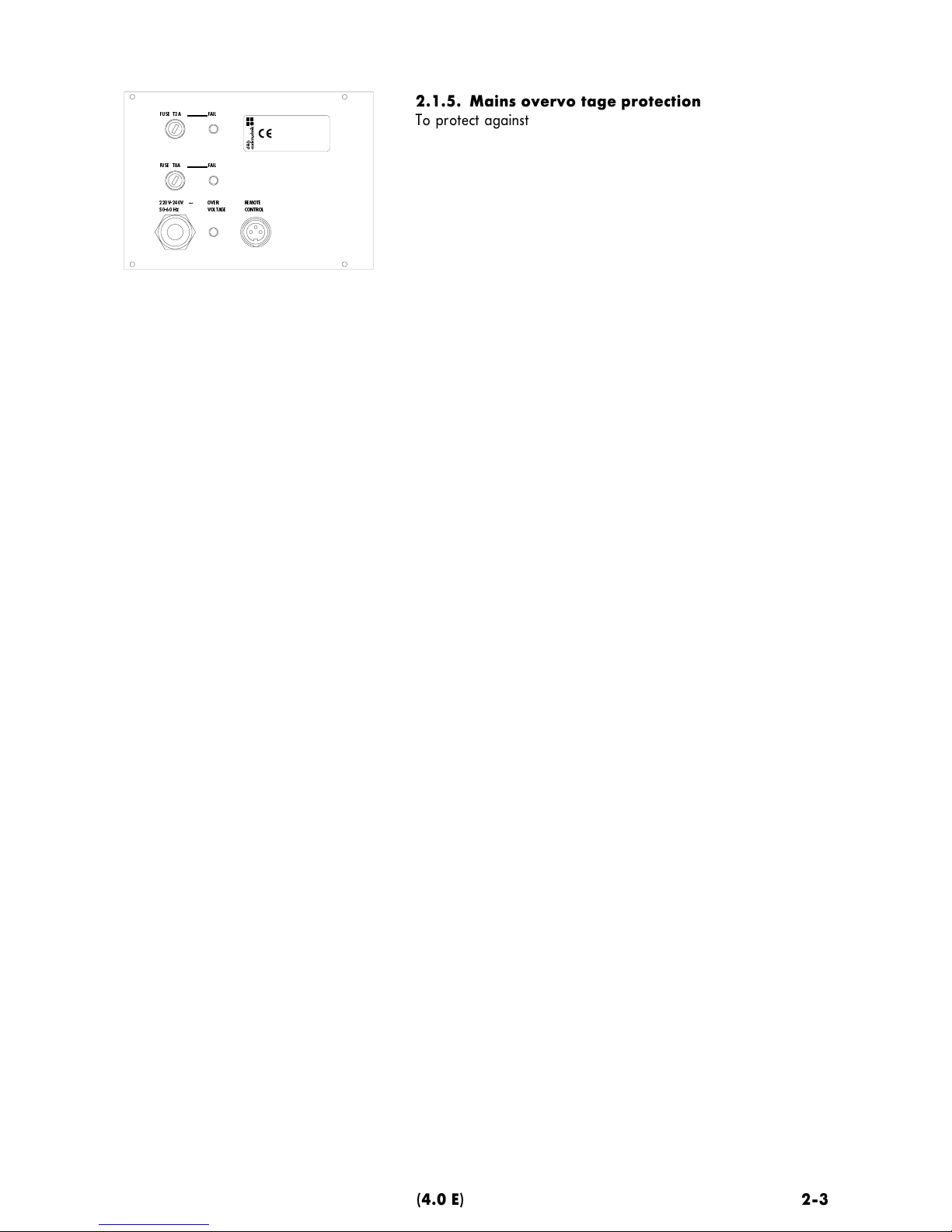
A1 mains input and fuses
REMOTE
CONTROL
FUSE T2A
220V-240V
∼
50-60 Hz OVER
VOLTAGE
FUSE T8A FAIL
FAIL
(4.0 E) 2-3
2.1.5. Mains overvoltage protection
To pro ec agains mains overvol age damage he A1 is fi ed wi h
an efficien , self-rese ing mains overvol age pro ec ion circui .
As soon as he mains supply vol age exceeds 265 V (115 V for he
100 V supply version) he overvol age pro ec ion circui responds
and isola es he mainframe power supply from he mains supply
leaving only a supervisory circui ac ive o moni or he mains sup-
ply vol age. The green POWER LED on he mainframe fron panel
goes ou and he OVER VOLTAGE LED on he mainframe rear pa-
nel comes on.
Only if he mains vol age drops below 255 V (111 V) is he mai-
nframe au oma ically reconnec ed o he mains supply and normal
opera ion resumed. This 10 V difference in he pro ec ion circui
swi ching levels (swi ching hys eresis) preven s he mainframe from
cycling on and off wi h a fluc ua ing mains supply vol age.
The pro ec ion circui will opera e wi h any mains overvol age up
o 400 V; allowing he A1 o survive connec ion across wo phases
of a hree phase supply.
2.1.6. Mains inrush current limiter
The mains inrush curren limi er ensures a slow "s ar -up" for he
mainframe and allows several mainframes connec ed o he same
mains supply circui o be swi ched on oge her wi hou emporarily
overloading he supply circui and causing a breaker o rip. The
inrush curren a swi ch on is limi ed o 5 A (230 V version).
No e ha repea edly and rapidly swi ching a mainframe on and
off will overhea and s ress he inrush curren limi er circui - a rear
panel fuse pro ec s he circui from damage.
2.1.7. Fuses
Two 20 mm delay fuses are fi ed on he mainframe rear panel -
an 8 A fuse for he mainframe power supply and a 2 A fuse pro-
ec ing he mains inrush curren limi er. If ei her fuse should blow
hen he red LED (FAIL) indica or nex o he respec ive fuseholder
will ligh .
2.1.8. Remote control & monitoring
The A1 is fi ed wi h a win wire remo e in erface for various levels
of remo e con rol and sys em supervision of he mainframe and i s
con roller module. The remo e in erface connec ion is op o-isola ed
and floa ing.
Basic Remote
The Basic Remo e is he simples way o implemen a remo e con rol
sys em. A mainframe can be remo ely powered on by simply ap-
plying an 18 - 28 VDC con rol vol age o he erminals of i s re-
mo e in erface connec or. Connec ing a simple de ec or circui o
he remo e in erface of a mainframe also allows remo e warning of
a mainframe faul . De ails of basic circui s for remo e power con -
rol and faul display are published in d&b echnical informa ion
bulle in TI 212.

2-4 A1 User Manual
Remote operation using the d&b Remote nterface
Bridge (R B)
The d&b RIB is housed in a 1 RU high, 19 rack moun enclosure.
Combina ions of 1 o 12 mainframes (A1 or P1200A) up o 500 m
away can be direc ly connec ed o a RIB I/O por by a win wire
bi-direc ional serial link.
From he fron panel of he RIB each mainframe can hen be remo-
ely powered on and off and i s power and error s a us moni ored.
A group of mainframes can be swi ched direc ly by he RIB fron
panel MASTER ON/OFF swi ch or remo ely via a connec ion o an
op o-isola ed inpu por on he rear panel of he RIB. Remo e indi-
ca ion of he error s a us of a mainframe group can also be re-
layed by he RIB.
Computer/M D control
The RIB can be con rolled by a compu er (RS232, RS422 or MIDI in-
erface) running sui able con rol sof ware or by a MIDI con rol de-
vice. Under compu er con rol, he following remo e con rol and dis-
play op ions become available:
Remote control
−
Power On/Off swi ching of mainframe
−
Level con rol from +0 o -63.5 dB in 0.5 dB s eps.
−
MUTE swi ching
−
Configura ion swi ching e.g. CUT, MON, e c.
Remote status information
−
Configura ion swi ch s a us
−
Mu e swi ch s a us
−
Level con rol se ing
−
Fron panel indica or s a us (ISP, GR, OVL e c.)
−
SPEAKER ID s a us
−
Pro ec s a us (DC pro ec , shor circui pro ec , hermal pro ec )
−
Hea sink empera ure in °C
−
Available headroom (pre-limi er)
−
Gain reduc ion (due o limi er opera ion)

A1 front panel
OFF
ON
REM
PWR
TEMP
REM
PROT
LOCK
LO HI
(4.0 E) 2-5
2.2. A1 controls & indicators
PWR - Power (green)
−
On. when he mainframe is connec ed o he mains supply, swi -
ched on and ready for use.
−
Off. The mainframe is no connec ed o or powered from he
mains supply. The mains overvol age pro ec ion has riggered
(see above) or he mainframe is no swi ched on.
−
Flashes during he ini ial power-up cycle for abou 2 seconds
and also when he mains overvol age pro ec ion circui is rigge-
red by an ex ernal faul (see also PROT below).
TEMP - Temperature (red)
−
Flashes. The mainframe has swi ched off because he maximum
permissable opera ing empera ure has been exceeded. This oc-
curs if he power amplifier hea sink empera ure exceeds 83° C or
if he mains power ransformer empera ure exceeds 120° C.
PROT - Protect (red)
As he wo mainframe power amplifier channels opera e indepen-
den ly here are separa e PROT indica ors for LO and HI channel.
−
On. An in ernal faul has been de ec ed on he mainframe chan-
nel concerned and ha channel has been disconnec ed (e.g. DC
vol age faul in he ou pu s age).
−
On and the PWR LED also flashes. An ex ernal faul has
swi ched off he affec ed power amplifier channel. Typical faul s
producing his indica ion are shor ed speaker cables or a load
impedance which is oo low for he amplifier o drive. Once he
cause of he faul has been iden ified and removed, ei her mu ing
and un-mu ing he con roller module, or powering he mainframe
off and on again, will rese he mainframe faul pro ec ion circui s
and allow normal opera ion o resume.
REM - Remote (green)
−
On. The mainframe is connec ed o he d&b RIB and ready for
communica ion.
LOCK (yellow)
−
On. The mainframe has been placed in a locked condi ion by a
remo e con rol sys em. This means ha all he mainframe and
con roller module con rols wi h he excep ion of he mains swi ch
are inac ive (locked ou ).
−
Off. The A1 mainframe is se o local opera ion, i.e. may be ope-
ra ed using he fron panel con rols.
OFF/REM/ON (power switch)
−
OFF. Wi h he excep ion of he mains overvol age pro ec ion cir-
cui , he mainframe is isola ed from he mains supply.
−
REM. The mainframe is se o remo e opera ion. If no remo e
con rol sys em is connec ed his se ing is equivalen o he power
swi ch OFF posi ion.
−
ON. The mainframe is swi ched on. In his swi ch posi ion, he re-
mo e con rol sys em can moni or and display he opera ional s a-
us of he mainframe bu canno change any se ings.

F2-CO loudspeaker output
PIN ASSIGNMENT OUTPUT
A LOW OUT +
B LOW OUT -
C SPEAKER ID
D SPEAKER ID
E SENSE DRIVE +
F SENSE DRIVE -
G HIGH OUT +
H HIGH OUT -
F2
A1 input signal connectors
INPUT
INPUT LINK
Pin assignment for remote
control
Pin 3 +)
Pin 1 –)
Pin 1 (GND)
Pin 2 (pos. signal)
Pin 3 (neg. signal)
Pin assignments on P1200A signal inputs
2-6 A1 User Manual
2.3. Connections
NPUT and NPUT L NK
The mainframe has a 3 pin XLR female inpu connec or. Benea h
and wired in parallel is a 3 pin male XLR connec or o provide an
inpu link - some imes called a pass- hrough connec or - used o
feed he inpu of he nex device in he sys em signal chain.
Transformer balanced input (option)
To preven sys em ground loops, he P1200A can be supplied wi h
ransformer balanced inpu s. The ransformers used are s udio
quali y orroidal ransformers able o handle signal levels up o
+28 dBu wi hou degrading he sys ems low frequency response.
The inpu balancing ransformer gives elec rical isola ion be ween
he source ou pu (e.g. mixing console) and con roller inpu s and
herefore preven s ground loops. A 22 kohms coupling resis or
preven s elec ros a ic loading of he mainframe.
REMOTE CONTROL
The A1 is fi ed wi h a wo-wire serial remo e con rol in erface. The
3 pin female DIN remo e con rol connec or is loca ed on he lef of
he A1 rear panel. The connec or is op o-coupled.
The remo e func ions are de ailed in sec ion 2.6. (Remo e con rol &
moni oring).
OUTPUT (loudspeaker outputs)
The speaker ou pu (s) are also loca ed on he mainframe rear pa-
nel. Bo h power amplifier ou pu s (LF & HF), SENSE DRIVE and
SPEAKER ID connec ions all ermina e on a single 8-pin CA-COM
connec or. The CA-COM is a par icularly robus and reliable bayo-
ne fi (locking) connec or.
Differen con roller modules have differen ou pu connec or pin
assignmen s which are prin ed on he panel nex o he connec-
or(s). Each con roller module speaker ou pu panel is described in
he la er sec ions of his manual along wi h he differen ac ive
loudspeakers and heir con roller modules.
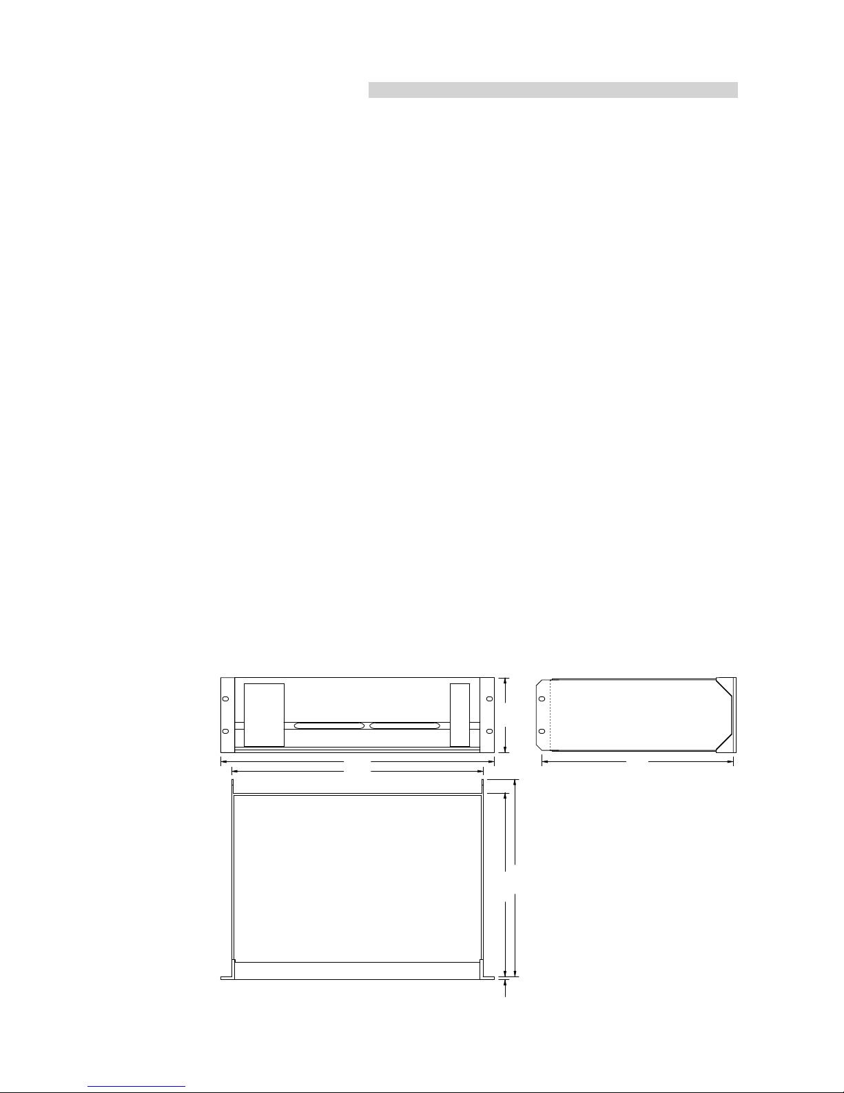
483
443
348 132
338
5323
A1 enclosure dimensions
(4.0 E) 2-7
2.4. Mainframe installation
P1200A mainframe enclosures are designed o fi a s andard 19"
equipmen rack or cabine .
The fron panel ven slo serves as a useful handle for lif ing and
moving mainframes in and ou of racks. The fron panel swi ches
are flush-fi ed and he level con rol(s) and mainframe power
swi ch are recessed o pro ec hem from acciden al damage and
unin en ional adjus men .
When specifying a rack, be sure o allow ex ra dep h (10 cm is
usually sufficien ) o accommoda e he cables and connec ors a he
rear of he mainframe(s).
When moun ing mainframes in o a 19" rack cabine , provide
addi ional suppor using shelves fixed o he inner sides of he
cabine or he moun ing holes provided on he mainframe rear-
moun ed rack ears - do no jus rely on fixing and suppor ing
mainframes by heir fron panels. This advice is par icularly
impor an if mainframes are being racked-up for ouring use.
Since he P1200A power amplifiers can genera e a lo of hea ,
please ensure, wha ever he moun ing or racking arrangemen ,
ha adequa e cool airflow is provided o avoid a build-up of ho
air inside he rack leading o overhea ing. The P1200A air in ake is
on he rear panel and he air ou le s are se in o he fron panel.
To main ain good airflow hrough mainframes we recommend
frequen cleaning of he fan fil ers. If mainframes are ins alled in
cabine s so ha direc access o he rear panel fil ers is no
possible, we recommend using addi ional fan modules wi h fron -
moun ed fil ers which can be easily replaced wi hou opening he
sealed cabine s. We will gladly advise on he choice of sui able fan
modules.
ignal
waveform
CF
Pout
[W]
Pin
[W]
Ploss
[W]
Square wave
1
2150
2900
750
Sine wave
1,4
1400
2130
730
Pink noise, com-
pressed music
3,5
200
500
300
Music wit me-
dium dynamic
range
5
100
300
200
Speec , music
wit wide dyna-
mic range
8
40
200
160
CF :Cres fac or
Pout :Maximum average ou pu po-
wer (sum of bo h channels)
Pin :Power inpu
Ploss :Power loss
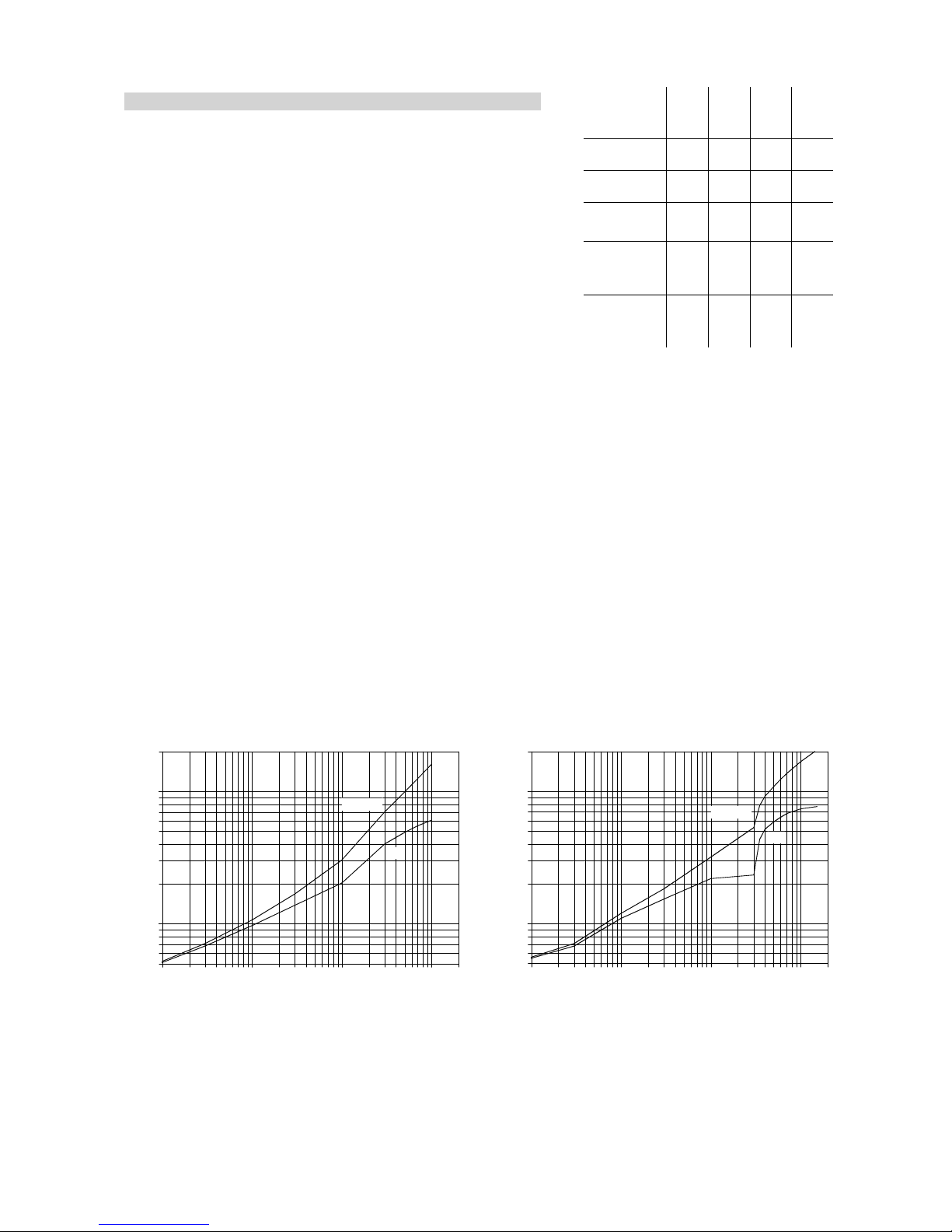
A1 Power balance
Average power consumption and loss of A1 as a factor of
output power with pink noise signal
(load impedance 4 / 8 ohms, both channels driven, sum of
output power of both channels)
Average power consumption and loss of A1 as a factor of
output power with sine wave signal
(load impedance 4 / 8 ohms, both channels driven, sum of
output power of both channels)
2000
1000
100
50
110 100 1000 2000
power [W]
average output power [W]
loss
consumption
2000
1000
100
50
110 100 1000 2000
power [W]
average output power [W]
loss
consumption
2-8 A1 User Manual
2.5. Power consumption and power loss
The power required from he mains supply and he was e hea
produced by he amplifiers power loss are variable figures
depending on he load impedance and he signal levels and
charac eris ics (e.g. speech, music).
In prac ice, he heore ical peak power consump ion of a sys em
will only be sus ained for a shor period of ime. Basing mains
curren and air condi ioning plan requiremen s on he peak power
consump ion of he sound sys em would resul in a generously
over-specified ins alla ion. The key fac or in power consump ion
calcula ions is he cres fac or of he music signal or speech signal -
he ra io of peak o sus ainable RMS vol age of he signal.
The able on he righ gives power figures for various ypes of
signal waveforms. The figures were measured on a A1 mainframe
driving a 4 and 8 ohms load (LO and HI channel) o he clipping
poin of bo h mainframe power amplifiers.
Power inpu and hermal power loss as a func ion of average
ou pu power for sine wave and pink noise signal waveforms can
also be derived from he wo graphs shown below (No e ha pink
noise signal reaches he clipping poin of he amplifiers a approx.
200 W average ou pu power).

1
0.001
0.010
0.1
0.2 110 100 1k 2k
Low 4 ohms
Low 8 ohms
THD + Noise (%) vs Output Level (W)
High 8 ohms
(4.0 E) 2-9
2.6. Technical specifications
Nominal output power............................................... 700 / 200 watts - 8 ohms
(THD+N < 0.1%, both channels d iven)..........................1200 / 350 watts - 4 ohms
Frequency response (1 dB)............................................................. 20 Hz - 50 Hz
measu ed at ated output powe , both channels d iven
Harmonic distortion (THD+N)................................................ < 0.05 % / 0.03 %
f om 0.1 W to ated output powe , 20 Hz - 20 kHz
Intermodulation distortion (SMPTE).................................. < 0.06 % / 0.02 %
f om 0.1 W to ated output powe
Residual noise............................................................................... > 112 dB / 114 dB
below ated output powe , 22 Hz - 22 kHz, unweighted, RMS
Damping factor at loudspeake output ................................................ > 50 / 100
20 Hz - 20 kHz, 4 ohms load
Crosstalk ............................................................................................................. < 55 dB
Protection circuits
Mains in ush cu ent limite ............................................................................................ 5 A
Switch-on delay .............................................................................................................. < 2 s
Ove voltage, DC output, ove tempe atu e and sho t ci cuits
INPUT.........................................................................................................XLR 3-pin female
Input impedance......................................................................................................44 kohms
elect onically o t ansfo me balanced (optional)
INPUT INK................................................................................................XLR 3-pin male
pa allel to input
C4-OUT (B2-CO only)..............................................................................XLR 3-pin. male
balanced, output load impedance .................................................................
≥
600 ohms
OUTPUT ...........................................................................................8-pin CA-COM, male
Pin assignments depend on type of loudspeake
General
Height x width x depth ...................... 3 ack unit x 483 mm (19") x 353 mm (13.9")
Weight with module fitted........................................................................ 22 kg (48.5 lbs)
Mains voltage (min/nominal/max) ........................ 195 /230 /265 V / 50 - 60 Hz
.................. (additionally with 115/230 V ve sion: 98 / 115 / 132 V / 50 - 60 Hz)
............................................................ (100 V ve sion: 85 / 100 / 115 V / 50 - 60 Hz)
Fuses ............................................................1 x 2 A Time Lag (T), 1 x 8 A Time Lag (T)
.......................................................................(115/230 V ve sion: 2 x 8 A Time Lag (T))
....................................(100 V ve sion: 1 x 5 A Time Lag (T), 1 x 16 A Time Lag (T))

This manual suits for next models
2
Table of contents


