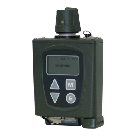
D-Industrial Technology Q200 User manual

Uson
Q200 User Manual
Revison 10
Updated September 2018

Q200 User Manual Preliminary
196045/Issue 10 i
Disclaimer
D-Industrial Technology Ltd. makes no representations or warranties with respect to the
contents or use of this manual and specifically disclaims any express or implied warranties of
merchantability or fitness for any particular purpose. Further D-Industrial Technology Ltd
reserves the right to revise this manual and to make changes to its content, at any time, without
obligation to notify any person or entity of such revisions or changes.
Copyright
No part of this manual may be reproduced or transmitted in any form or by any means,
electronic or mechanical, including photocopying and recording, for any purpose other than the
purchaser's personal use without the written consent of the copyright holder.
©D-Industrial Technology Ltd, October 2003-2016. All rights reserved.
Trademarks
Q200 ®is a registered trademark of D-Industrial Technology Ltd
SPC-PC IVTM is a registered trademark of Quality America, Inc.
WindowsTM is a trademark of Microsoft Corporation.
Sales and Support
US and North America
Creative Solutions
PO Box 14511
Scottsdale, AZ 85267
+1 512 588-2002


Q200 User Manual Preliminary
200120/Revision 10 i
Document History
Part Number: 200120
Revision History:
Issue Change
Note Date Description
1 N/A 04/02/1994 First Edition
2 N/A 12/03/1994 First Revision
3 N/A 14/12/1994 Second Revision
4 1348 06/01/1995 Spares Updated
5 1415 25/01/1996 EC Revision
6 0051 02/07/1997 Sinter References
7 0263 08/11/1999 H, M & L Sinters. Fixed exponent display
8 0536 05/02/2002 Sales support information and document format
updated.
9 0627 1/10/2003 Sales support information updated
10 0760 2/26/2007Added ROHS declaration

Preliminary Q200 User Manual
ii 200120/Revision 10
About This Manual
This manual is designed to provide full information about the setting up and use of the
Q200.
•Section 1 WARNING AND CAUTIONS gives general information to be aware
of when installing or using the Q200.
•Section 2 INTRODUCTION gives a general introduction to the Q200 and its
operation.
•Section 3 UNPACKING provides a checklist for the components supplied with
the Q200.
•Section 4 INSTALLATION REQUIREMENTS explains the installation
requirements for the Q200 before use.
•Section 5 CONSOLE FAMILIARISATION familiarises the user with the Q200's
console and front panel interface.
•Section 6 HAND UNIT FAMILIARISATION familiarises the user with the hand
unit, key panel and controls.
•Section 7 POWER UP AND INSTALLATION this section describes how to
switch the Q200 on and the initialisation routine that follows.
•Section 8 PROGRAMMING THE Q200 gives a detailed description of each
program function and instructions for viewing and altering them.
•Section 9 CALIBRATING THE Q200 describes the procedure for calibrating
the Q200 to a standard leak.
•Section 10 THE Q200 IN USE gives guidance on the precautions that may
need to be taken when calibrating and using the Q200 in a typical industrial
environment.
•Section 11 INTERFACING THE Q200 describes how the Q200 can be
connected to peripheral devices such as printers or chart recorders.
•Appendix A Q200 Specification gives a full specification for the Q200.
•Appendix B Preventative Maintenance gives information on general
preventative maintenance for the Q200.
•Appendix C Fault/Error/Warning Messages explains possible fault, error and
warning conditions and suggests corrective actions.
•Appendix D Spares/Options List gives a list of the spares and options available
for the Q200.
•Appendix E RS232 Connector Details lists the pin-outs and connectors for the
Q200.
•Appendix F Applications describes some of the typical application areas in
which the Q200 is used.

Q200 User Manual Preliminary
200120/Revision 10 iii
•Appendix G Changing the Internal Gas Cylinder details the procedure for
changing the internal gas cylinder on the Q200.
•Appendix H Installing/Changing the Battery details the procedure for installing
and changing the battery on the Q200.
•Appendix I Changing The Probe/Sinter details the procedure for changing the
Q200's hand unit probe and sinter.
•Appendix J Leak Rate and Concentration Formulae lists the formulae for
converting between leak rates in different units and between leak rate and
concentration.
•Appendix K Program Structure details the program structure for reference
when programming the Q200 for use.
•Glossary of terms used within this manual.
•Index.


Q200 User Manual Contents
200120/Revision 10 1
Table of Contents
Disclaimer.........................................................................................................................i
Copyright..........................................................................................................................i
Trademarks......................................................................................................................i
Sales and Support............................................................................................................i
Document History.............................................................................................................i
About This Manual ..........................................................................................................ii
Table of Contents........................................................................................................... 1
1.0 WARNING AND CAUTIONS............................................................................1-1
1.1 HAND UNIT DETECTOR..............................................................................1-1
1.2 Sinter.............................................................................................................1-1
1.3 Configuring the Q200....................................................................................1-1
1.3.1 Changing from capillary mode to sinter mode.........................................1-2
1.3.2 Changing from sinter mode to capillary mode.........................................1-2
1.3.3 Changing between sinters.......................................................................1-3
1.3.4 Re-configuring the instrument..................................................................1-3
1.3.5 Measuring ranges and configuration codes.............................................1-4
1.4 ARGON GAS SUPPLY.................................................................................1-5
1.5 POWER SUPPLY .........................................................................................1-5
1.6 TRANSPORTING THE Q200........................................................................1-6
1.7 DISPOSAL....................................................................................................1-6
1.8 ENVIRONMENTAL.......................................................................................1-6
1.9 EC DECLARATION OF CONFORMITY .......................................................1-7
2.0 INTRODUCTION..............................................................................................2-1
3.0 UNPACKING....................................................................................................3-1
4.0 INSTALLATION REQUIREMENTS..................................................................4-1
4.1 REMOVING THE CASE LID.........................................................................4-1
4.2 GAS SUPPLY ...............................................................................................4-1
4.3 POWER SUPPLY .........................................................................................4-2
4.4 STORAGE AND OPERATING ENVIRONMENT ..........................................4-2
4.5 OPERATING MODES...................................................................................4-2
4.5.1 PORTABLE INSTALLATION...................................................................4-2
4.5.1.1 CHECKING THE INTERNAL ARGON SUPPLY..............................4-3
4.5.1.2 CHECKING THE BATTERY............................................................4-3
4.5.2 FIXED INSTALLATION............................................................................4-3
4.5.2.1 RUNNING FROM AN EXTERNAL GAS SUPPLY...........................4-3
4.5.2.2 RUNNING FROM THE EXTERNAL POWER SUPPLY...................4-4
5.0 CONSOLE FAMILIARISATION........................................................................5-1
5.1 FRONT PANEL LAYOUT .............................................................................5-1
5.1.1 KEY-SWITCH ORIENTATION.................................................................5-1
5.1.2 FRONT PANEL KEYS.............................................................................5-2
5.1.3 BATTERY CHARGER INDICATOR.........................................................5-2
6.0 HAND UNIT FAMILIARISATION......................................................................6-1
6.1 HAND UNIT KEYS........................................................................................6-2
6.2 HAND UNIT INDICATORS ...........................................................................6-2
6.2.1 WARNING LED .......................................................................................6-2
6.2.2 PEAK HOLD LED....................................................................................6-2
6.3 HAND UNIT BAR GRAPH DISPLAY............................................................6-2
7.0 POWER UP AND INSTALLATION...................................................................7-1
7.1 SWITCH ON .................................................................................................7-1
7.2 INSTALLATION ............................................................................................7-1
8.0 PROGRAMMING THE Q200............................................................................8-1
8.1 CALIBRATE MENU ......................................................................................8-1
8.1.1 CALIBRATION LEVEL.............................................................................8-1
8.1.2 RE-CALIBRATION INTERVAL................................................................8-2

Q200 User Manual Contents
2200120/Revision 10
8.1.3 CALIBRATION FACTOR..........................................................................8-3
8.2 CONFIGURE MENU .....................................................................................8-3
8.2.1 CLEAN TIME............................................................................................8-3
8.2.2 ALARM LEVEL.........................................................................................8-3
8.2.3 TRACE GAS CONCENTRATION ............................................................8-4
8.2.4 AUTO ZERO ............................................................................................8-5
8.2.5 DISPLAY TYPE........................................................................................8-5
8.2.6 RESET PARAMETERS............................................................................8-6
8.2.7 GAS SUPPLY...........................................................................................8-6
8.3 DIAGNOSTICS MENU ..................................................................................8-7
8.3.1 BATTERY VOLTAGE...............................................................................8-7
8.3.2 TEMPERATURE......................................................................................8-7
8.3.3 DETECTOR FREQUENCY......................................................................8-7
8.3.4 RE-CALIBRATION...................................................................................8-8
8.3.5 SOFTWARE VERSION NUMBER ...........................................................8-8
8.4 SET DATE/TIME MENU................................................................................8-8
8.4.1 DATE........................................................................................................8-8
8.4.1.1 DAY..................................................................................................8-9
8.4.1.2 MONTH ............................................................................................8-9
8.4.1.3 YEAR................................................................................................8-9
8.4.2 TIME.......................................................................................................8-10
8.4.2.1 HOURS...........................................................................................8-10
8.4.2.2 MINUTES .......................................................................................8-10
8.5 EXITING THE MENU STRUCTURE ...........................................................8-11
9.0 CALIBRATING THE Q200................................................................................9-1
10.0 THE Q200 IN USE.......................................................................................10-1
10.1 STANDBY MODE........................................................................................10-1
10.2 SAMPLE MODE ..........................................................................................10-1
10.3 INSTRUMENT CALIBRATION....................................................................10-2
10.4 GENERAL TIPS ON LEAK DETECTION....................................................10-3
10.5 ADJUSTING THE VOLUME........................................................................10-6
10.6 BACKGROUND CONTAMINATION............................................................10-6
10.7 RESULTS STORAGE AND PRINTOUT......................................................10-7
11.0 INTERFACING THE Q200 ..........................................................................11-1
11.1 INTERFACING TO A PRINTER..................................................................11-1
11.2 INTERFACING TO A CHART RECORDER................................................11-1
Appendix A Q200 Specification.................................................................A-1
Appendix B Preventative Maintenance .....................................................B-1
Appendix C Fault/Error/Warning Messages..............................................C-1
Appendix D Spares/Options List ...............................................................D-1
Appendix E RS232 Connector Details ......................................................E-1
Appendix F Applications............................................................................ F-1
Appendix G Changing the Internal Gas Cylinder ......................................G-1
Appendix H Installing/Changing the Battery..............................................H-1
Appendix I Changing The Probe/Sinter.......................................................I-1
Appendix J Leak Rate and Concentration Formulae..................................J-1
Appendix K Program Structure..................................................................K-1
Glossary.......................................................................................................................L-1
Index................................................................................................................................i

Q200 User Manual Contents
200120/Revision 10 3
List Of Figures
Figure 1: Q200 Case Lid Containing Accessories.......................................................3-1
Figure 2 Removing the Case Lid.................................................................................4-1
Figure 3: Front Panel Layout.......................................................................................5-1
Figure 4: Hand Unit Display and Keyboard.................................................................6-1
Figure 5: Changing the Internal Gas Cylinder............................................................ G-1
Figure 6: Changing the Battery ...................................................................................H-1
Figure 7: Fitting the Probe............................................................................................I-1
Figure 9: Location of Sinter..........................................................................................I-2
Figure 10: Q200 Menu Structure.................................................................................K-1


Q200 User Manual WARNING AND CAUTIONS
200120/Revision 10 1-1
1.0WARNINGAND CAUTIONS
This section explains the warnings and cautions that should be observed when
installing or using the Q200.
1.1 HAND UNIT DETECTOR
The detector operates at elevated temperatures; the user should proceed with caution
whenever the hand unit nozzle is removed.
The detector contains a radioactive source that should never be tampered with. The
detector contained within the hand unit has the following characteristics:
Nuclide Nickel 63
Radiation Beta rays
Content 370 MBq
Beta energy 60 keV Max
Range in air 50 mm approximately
Half-life 100 years
The primary Beta rays are completely contained within the detector cell and provide no
hazard to the user during normal operation. National Regulations relating to the control
of radioactive sources vary from country to country. It is a requirement in some
countries, and a practice that we would recommend that a competent person be
appointed to be responsible for the instrument. Their duties would be to ensure proper
care is taken of the instrument and all users are instructed in the use of the instrument
and not to attempt access to the radioactive sources. In the event of damage or loss
occurring, there may be a requirement to notify the competent authority.
Specific instructions may accompany this manual describing any further national
regulations governing the use, storage and transportation of equipment containing
radioactive sources. In the UK the radioactive source must be checked at least every
24 months for leakage. The supplier of the equipment can provide this service.
1.2 SINTER
Periodically the user should remove the nozzle and inspect the sinter, see Appendix I
for more information. A new sinter should be fitted if the current sinter is discoloured
indicating deposits of contaminants exist on its surface. Progressive blockage of the
sinter can also be observed by progressive reduction in detector response to standard
leaks or increasing calibration factors when performing calibration sequences.
1.3 CONFIGURING THE Q200
The Q200 has been factory configured to match your requirements with respect to
language option, the type of trace gas to be used, probe type and the displayed units.
If a configuration change is required, it can be performed as detailed below.

Q200 User Manual WARNING AND CAUTIONS
1-2 200120/Revision 10
1.3.1 CHANGING FROM CAPILLARY MODE TO SINTER MODE.
CAUTION: Before changing the hand unit probe ensure that the hand unit
detector block is cool.
1. Remove the capillary probe nozzle from the nozzle cone by pulling the probe
nozzle out of the nozzle cone. Ensure that the capillary probe nozzle is pulled
out of the nozzle cone in the line of the hand unit to avoid bending the capillary
probe needle.
2. Unscrew the nozzle cone from the hand unit.
3. Unscrew the capillary needle probe and its housing from the front face of the
detector assembly and store in a clean dry place. Note that the small knurled
cap on the housing retains the capillary needle probe in the housing.
Unscrewing the housing using the larger knurled flange adjacent to the front
face of the detector assembly will allow the needle probe and its housing to be
removed from the detector assembly as a single entity.
4. Locate the required sinter and inspect the seal around the periphery of the
sinter to ensure that it is not damaged. Damage to the seal will compromise the
performance of the instrument by allowing an excessive amount of air to enter
the detector. Appendix D contains details of replacement seals that can be
fitted to the sinter. Fit the sinter into the front of the detector assembly. Use a
broad flat bladed screwdriver to tighten the sinter into the detector assembly.
5. Screw the nozzle cone back into place on the hand unit.
6. Push the sinter probe nozzle firmly into the nozzle cone.
7. Re-configure the instrument as outlined in 1.3.3.
8. Perform a cleaning cycle of at least one hour.
1.3.2 CHANGING FROM SINTER MODE TO CAPILLARY MODE.
CAUTION: Before changing the hand unit probe ensure that the hand unit
detector block is cool.
1. Unscrew the nozzle cone from the hand unit.
2. Using a broad bladed screwdriver, unscrew the sinter assembly from the front
face of the detector assembly and store in a clean dry place.
3. Remove the sinter probe nozzle from the nozzle cone.
4. Locate the capillary needle probe and it’s housing and inspect the seal around
the periphery of the housing to ensure that it is not damaged. Damage to the
seal will compromise the performance of the instrument by allowing an
excessive amount of air to enter the detector. Appendix D contains details of
replacement seals that can be fitted to the housing. Screw the capillary needle
probe and its housing into the front face of the detector assembly until finger
tight.
5. Screw the nozzle cone back into place on the hand unit.

WARNING AND CAUTIONS
Q200 User Manual
200120/Revision 10 1-3
6. Push the capillary probe nozzle over the capillary needle probe and into the
nozzle cone, taking care to ensure that no bending stresses are applied to the
capillary needle probe.
7. Re-configure the instrument as outlined in 1.3.3.
8. Perform a cleaning cycle of at least one hour.
1.3.3 CHANGING BETWEEN SINTERS
CAUTION: Before changing the hand unit probe ensure that the hand unit
detector block is cool.
1. Unscrew the nozzle cone from the hand unit.
2. Using a broad bladed screwdriver, unscrew the sinter assembly from the front
face of the detector assembly and store in a clean dry place.
3. Locate the required sinter and inspect the seal around the periphery of the
sinter to ensure that it is not damaged. Damage to the seal will compromise the
performance of the instrument by allowing an excessive amount of air to enter
the detector. Appendix D contains details of replacement seals that can be
fitted to the sinter. Fit the sinter into the front of the detector assembly. Use a
broad flat bladed screwdriver to tighten the sinter into the detector assembly.
4. Screw the nozzle cone back into place on the hand unit.
5. Re-configure the instrument as outlined below.
6. Perform a cleaning cycle of at least one hour.
1.3.4 RE-CONFIGURING THE INSTRUMENT
1. Switch the instrument on and ensure that the security key-switch is in the
program position.
2. With the console display reading 'Calibrate' press the Zero (hand unit) key
and the Standby\Run (console) key simultaneously. This will bring up a four-
digit numeric configuration code on the console display. The first digit of the
code will be flashing.
Digit 1234
Code 1234
Code
Digit 1: Agent: 0. English

WARNING AND CAUTIONS
Q200 User Manual
1-4 200120/Revision 10
1. American
2. German
Digit 2: Units: 0.ml/s
1. ppm
Digit 3: Gas Type: 0. SF6
1. Undefined
Digit 4: Probe Type: 0. H Sinter
1. Capillary
2. M Sinter
3. L Sinter
3. Using the Increment \ Decrement , Scroll Left \ Scroll Right keys the
desired configuration code can be entered. If the operator then presses the
Select key the instrument will verify that the code entered is a valid one. If an
invalid code is entered, then an 'Invalid Code' message will be displayed for a
two second interval, then the operator will be given two further chances to re-
enter a valid code. If a valid code is not entered within three attempts the
instrument will revert back to the 'Configure' prompt.
4. If the Select
key is pressed with a valid code being displayed, a 'Valid Code'
message will be displayed for a two-second interval. The instrument will then
perform to the new configuration parameters. Note that changing the
configuration code clears existing parameters and will set calibration and alarm
levels to the default values for the new configuration.
CAUTION: If the instrument is re configured then it should be re calibrated as
described in this manual.
1.3.5 MEASURING RANGES AND CONFIGURATION CODES
The following tables illustrate the measuring ranges available for the various inlet
probes based on 100% trace gas concentration:

Q200 User Manual WARNING AND CAUTIONS
200120/Revision 10 1-5
Leak-Rate Measuring Ranges For SF6 / ml/s
Probe Type Capillary H Sinter M Sinter L Sinter
Range 0.0 x 10⁻¹⁰
⇓
1.8 x 10⁻⁷
0.0 x 10⁻⁸
⇓
1.8 x 10⁻⁵
0.0 x 10⁻⁷
⇓
1.8 x 10⁻⁴
0.0 x 10⁻⁶
⇓
1.8 x 10⁻³
Alarm/Cal. 1.0 x 10⁻¹⁰
⇓
1.8 x 10⁻⁷
1.0 x 10⁻⁸
⇓
1.8 x 10⁻⁵
1.0 x 10⁻⁷
⇓
1.8 x 10⁻⁴
1.0 x 10⁻⁶
⇓
1.8 x 10⁻³
Config. Code 0001 0000 0002 0003
Concentration Measuring Ranges For SF6 / ppm
Probe Type Capillary H Sinter M Sinter L Sinter
Range N/A 0.0
⇓
18.09
0.0
⇓
180.0
0.0
⇓
1800
Alarm/Cal. N/A 0.01
⇓
18.00
0.1
⇓
180.0
1
⇓
1800
Config. Code N/A 0100 0102 0103
When the M or L Sinters or the Capillary probe are fitted, the ranges over which the
instrument may be calibrated are automatically changed to match the usable range of
the instrument. Appendix A contains a full list of the operating, calibration and alarm
ranges for all the inlet probes over a range of trace gas concentrations.
1.4 ARGON GAS SUPPLY
The instrument requires a supply of Argon that is at least 99.998% pure. This is
supplied with the instrument in a gas cylinder that conforms to BS 5045/3/B.
The gas cylinder should be filled to a pressure no greater than 200 bar (2900 PSIG)
maximum, and regularly checked for damage or fatigue and that the cylinder is still
within the validity of the test period indicated by the plastic collar on the stem of the
cylinder valve.
If an external gas supply is used the pressure supplied to the inlet port should not
exceed 4 bar (58 PSIG) maximum.
1.5 POWER SUPPLY
The instrument is supplied with an internal 12 Volt, gel electrolyte battery and a battery
charger. Both items are designed for use with the Q200 only. The manufacturer
accepts no responsibility if either item is operated with any equipment other than the
Q200. Information on spares may be found in Appendix D.
The battery charger must be run only from a mains supply that has a protective earth. It
is designed to be used on a flat surface next to the instrument and with adequate
clearance for ventilation. It should not be used whilst still located in the lid infill.

Q200 User Manual WARNING AND CAUTIONS
1-6 200120/Revision 10
The internal 12 Volt battery has inline protective fuse T2A/250V. A replacement fuse
must be of an appropriate type and rating.
1.6 TRANSPORTING THE Q200
Transport of the instrument is subject to regulation in most countries. It is also subject
to international rules when transportation is between two different countries. If the
instrument needs to be transported, seek expert advice prior to shipping.
1.7 DISPOSAL
If there is an accident that damages the hand unit beyond repair or when the
instrument has exceeded its useful life, the unit must be disposed of through an
approved contractor. In the United Kingdom, the manufacturer can accept units for
disposal. Note that a charge will be made for the disposal of radioactive sources. In
other countries, the National Radiological Protection Organisation should be contacted
for advice.
1.8 ENVIRONMENTAL
Do not use the instrument:
•In explosive atmospheres.
•Outside the specified operating temperature range.
•With hazardous or toxic gases.
•In an environment where water could be drawn into the probe.
•Where the variation in background level is greater than the calibration level.

WARNING AND CAUTIONS
Q200 User Manual
200120/Revision 10 1-7
1.9 EC DECLARATION OF CONFORMITY
As detailed under the following:
•The European Low Voltage Directive 73/23/EEC (amended by 93/68/EEC).
•The Electromagnetic Compatibility Directive 89/336/EEC (amended by 91/263/EEC
and 92/31/EEC), the declaration of conformity is provided for the following:
Equipment: Q200 Trace Gas Leak Detector
Manufacturer: Uson Ltd
WesternWay
Bury St. Edmunds
Suffolk
United Kingdom
IP333SP
Transposed Harmonised Standards: BS EN 61010-1:1993 Safety requirements
for electrical equipment for measurement,
control and laboratory use.
BS EN 50081-1:1992 Electromagnetic
Compatibility: Generic emission standard
for light industry.
BS EN 50082-1:1992 Electromagnetic
Compatibility: Generic immunity standard
for light industry.
Name Of Responsible Person: Mr A Hawes
Signature:
Date: 12 March 1996
Position: Senior Development Engineer.
Address Of Responsible Person: Uson Ltd
WesternWay
Bury St. Edmunds
Suffolk
United Kingdom
IP333SP


Q200 User Manual INTRODUCTION
200120/Revision 10 2-1
2.0INTRODUCTION
The Q200 is a high sensitivity leak detector used to locate and quantify leaks with
electron capturing trace gases. The instrument may be used in a variety of industrial
and scientific applications and environments. It is lightweight and robust and comprises
a hand unit, control console, rechargeable battery and Argon gas cylinder, contained
within a case for complete portability. Facilities are built in to allow the instrument to be
operated using external gas and power supplies.
The instrument is microprocessor based, using a Vacuum Fluorescent Display (VFD) to
provide a rapid and accurate readout of leak rates. The built-in memory is capable of
storing up to one hundred separate leak rate readings, which can be output to a printer
via the built in RS232 interface connector.
The detection principle uses a single Electron Capture Detector (ECD), utilising a low
power radioactive source contained within the hand unit. To measure for leaks, the
component under test is filled with a trace gas until there is a slightly higher pressure
than ambient within the component. This condition will cause the trace gas to leak
through any cracks, holes or porous areas within the component. Leaking trace gas will
then be detected and quantified by the Q200.
Each instrument is factory configured for a specific trace gas and measurement unit.
By default the instrument is configured for SF6although configuration for other gases is
available on special order.
This manual is written specifically for an instrument configured to SF6, H Sinter
and ml/sec. Instruments configured for other gases, sinters and units will
perform identically except that some display formats are different, and the range
and step sizes for calibration and alarm levels are different. The user may
convert between leak rates in different units by referring to Appendix J.
Table of contents
Popular Security Sensor manuals by other brands

GJD
GJD D-TECT Dual Tech GJD360/AM installation guide

Optex
Optex WX Infinity Series installation instructions

DSC
DSC PowerG PG9985 installation guide

Philio Technology Corporation
Philio Technology Corporation PSP05-A manual

GasTech
GasTech F-GUARD IR3-HD user manual

Baumer
Baumer URDK 10P8914/KS35A quick start guide

Theben
Theben compact office quick start guide
B.E.G. LUXOMAT
B.E.G. LUXOMAT PD2-M-DALI/DSI-1C Installation and operating instruction

MKS
MKS Ophir FPD-IG-175 user manual

Baumer
Baumer UNDK 30U6104 quick start guide

IMMOOS
IMMOOS SS1 mGB operating instructions

Eaton
Eaton MAB50R Installation and operation manual
