d2itsu CSAD UiAWP 100 PS Series User manual

MODULAR CHILLER INVERTER
CSAD UiAWP 100 PS
CSAD UiAWP 200 PS
CSAD UiAWP 300 PS
SERIE
CSAD UiAWP 100/200/300 PS
EDITION
04/09
IMEn
INSTALLATION
MANUAL
Models:

ACCESSORIES
1
1 1
Purpose
Shape
Quantity
Unit
1
CONTENTS PAGE
1INTRODUCTION.....................................................................1
2SAFETY CONSIDERATIONS.................................................2
3BEFORE INSTALLATION......................................................3
4 IMPORTANT INFORMATION ON REFRIGERANT...............4
5SELECTION OF INSTALLATION SITE..................................4
6PRECAUTIONS ON THE INSTALLATION............................4
7 CONNECTION DRAWING OF PIPELINE SYSTEM...............9
8OVERVIEW OF THE UNIT.....................................................10
9 START-UP AND CONFIGURATION.....................................36
10 TEST RUN AND FINAL CHECK...........................................37
11 MAINTENANCE AND UPKEEP............................................39
12 APPLICABLE MODELS AND MAIN PARAMETERS...........47
13 INFORMATION REQIUREMENTS .......................................48
ACCESSORIES
Total water outlet
temperature
Sensor Casing
Installation &
Operation
manual
Installation
manual of
wired controller
Transformer
Use for installation
(only need for setting the main module)
Installation Manual___________________________________________________________________________________

Use conditions of the unit
1. INTRODUCTION
Ambient temperature (℃)
a. The standard voltage of power supply is 380-415V 3N~50Hz, the minimum allowable voltage is 342V, and the maximum voltage is 456V.
b. The unit must be operated as the following outdoor temperature:
CSAD UiAWP 100 PS
CSAD UiAWP 200 PS
Outlet water temperature (℃)
CSAD UiAWP 300 PS
CSAD UiAWP 100 PS
CSAD UiAWP 200 PS
CSAD UiAWP 300 PS
-20
-10
Fig. 1-1 Cooling operating range of CSAD UiAWP 100 PS
and CSAD UiAWP 200 PS
Ambient temperature (℃)
Outlet water temperature (℃)
Fig. 1-2 Cooling operating range of CSAD UiAWP 300 PS
Fig. 1-3 Heating operating range of CSAD UiAWP 100 PS
and CSAD UiAWP 200 PS
0
10
20
30
40
50
0 10 20 30
-20
-10
0
10
20
30
40
50
0 10 20 30
-25
-15
-5
5
15
25
35
20 30 40 50 60
-25
-15
-5
5
15
25
35
20 30 40 50 60
Outlet water temperature (℃)
Fig. 1-4 Heating operating range of CSAD UiAWP 300 PS
1
Installation Manual___________________________________________________________________________________

CAUTION
WARNING
WARNING
Failure to observe a warning may result in death.
CAUTION
Failure to observe a caution may result injury or damage
to the equipment.
To prevent injuries or property losses, make sure to observe the
following instructions. Failure to do so may cause injuries or losses.
There are two types of safety instructions: warning and caution.
Whichever type it is, you must read the information listed under it
carefully.
Get your distributor or a professional to install the product.
The installation personnel must be equipped with the
professional knowledge. When you install on your own, any
mistake you made during the operations may lead to a fire,
electric shock, injury or water leakage.
When purchasing items locally, purchase those designated by
our company.
Failure to do so may result in a fire, electric shock, or water
leakage. Note to entrust a professional to install those items.
When powering the unit, follow the regulations of the local
electric company.
Make sure the unit is grounded reliably in accordance with the
laws. Otherwise, it may cause electric shock. When moving or
reinstalling the modular unit, get your distributor or a
professional to do so.
If installed improperly, a fire, electric shock, injury or water
leakage may occur. Never modify or repair the unit on your own.
Otherwise, a fire, electric shock, injury or water leakage may
occur. Get your distributor or a professional to do so.
Ensure that the residual current device (RCD) is installed.
The RCD must be installed. Failure to install it may result in
electric shock.
Connect the cable properly.
Otherwise, it may cause damage to electrical parts.
Do not operate the unit near flammables (paint, coating, gasoline
and chemical reagents) lest fire or explosion may occur. In the
unlikely event of a fire, please turn off the main power immediately
and put out the fire using an extinguisher.
Do not touch refrigerant discharge parts to prevent being burnt.
Service the unit regularly according to the manual, to ensure that
the unit is in good condition.
When the unit stops due to a fault, refer to the Fault Analysis and
Troubleshooting in this manual, or contact the local customer
service centre. Do not start the unit until the fault is eliminated.
When finding refrigerant or chilled water (cooling water) leaks, turn
off all the switches immediately. If you cannot do so through
operating the controller, do not restart the unit unless the fault is
located and eliminated.
Use fuses with designated capacity. Do not use iron wires or
copper wires, as doing so may result in serious damages to the
unit or a fire.
2. SAFETY CONSIDERATION
2
Installation Manual___________________________________________________________________________________

3. BEFORE INSTALLATION
Handling of the unit
The angle of inclination should be between 45º and 70º when carrying the unit in case of overturn of the unit.
a. Rolling handling: several rolling rods of the same size are placed under the base of the unit, and the length of each rod must be
more than the outer frame of the base and suitable for balancing of the unit.
b. Lifting: each lifting rope (belt) should be able to bear 4 times the weight of the unit. Check the lifting hook and ensure that it is firmly
attached to the unit. To avoid damages to the unit, a protective block made of wood , cloth or hard paper should be placed between the
unit and rope when lifting, and its thickness should be 50mm or more. It is strictly forbidden to stand under the machine when it is
hoisted.
Fig. 3-1 Lifting of the unit
Lifted cable
4 protective blocks should be placed.
Unilateral distance should be 50mm or more.
The angle of inclinaton (45~70°)
Lifted hook
The angle of inclinaton (45~70°)
3
Installation Manual___________________________________________________________________________________

4. IMPORTANT INFORMATION ON
REFRIGERANT
5. PRECAUTIONS OF INSTALLATION
NOTE
The selected installation site of the unit should facilitate connection
of water pipes and wires, and be free from water inlet of oil fume,
steam or other heat sources. Besides, the noise of the unit and cold
and hot air should not influence the surrounding environment.
This product contains fluorinated greenhouse gases covered
by the Kyoto Protocol. Do not vent gases into the atmosphere.
Refrigerant type: R410A
GWP value: 2088
GWP = global warming potential
5.1 Units can be installed on the ground or proper place on a roof,
provided that sufficient ventilation can be guaranteed.
5.2 Do not install the unit in a scenario with requirements on noise
and vibration.
5.3 When installing the unit, take measures to avoid exposure to
direct sunlight, and keep the unit away from boiler pipeline and
surroundings which might corrode the condenser coil and copper
pipes.
5.4 If the unit is within the reach of unauthorized personnel, take
protective measures for safety considerations, such as installing a
fence. These measures can prevent man-caused or accidental
injuries, and can also prevent the electrical parts in operation from
being exposed when the main control box is opened.
5.5 Install the unit on a foundation at least 300 mm high above the
ground, where the floor drain is provided, to ensure that water
does not accumulate.
5.6 If installing the unit on the ground, put the steel base of the
unit on the concrete foundation, which must be as deep as into
the frozen soil layer. Ensure the installation foundation is
separated from buildings, as the noises and vibration of the unit
may adversely affect the latter. By means of the installation holes
on the unit base, the unit can be fastened on the foundation
reliably.
5.7 If the unit is installed on a roof, the roof must be strong
enough to bear the weight of the unit and the weight of
maintenance personnel. The unit can be placed on the concrete
and groove-shaped steel frame, similar to the case when the unit
is installed on the ground. The weight-bearing groove-shaped
steel must match the installation holes of the shock absorber and
is wide enough to accommodate the shock absorber.
5.8 For other special requirements for installation, please consult
the building contractor, architectural designer or other
professionals.
Model
Refrigerant(kg) Tonnes CO2equivalent
10.50
17.00
27.00
21.94
35.50
56.36
Factory charge
CSAD UiAWP 100 PS
CSAD UiAWP 200 PS
CSAD UiAWP 300 PS
Table 4-1
Left view
Top view
6.1.2 CSAD UiAWP 200 PS
E
D
F
A
A
B
C
B
Left view
6. INSTALLATION OF THE UNIT
6.1 Outline dimensional drawing
6.1.1
CSAD UiAWP 100 PS
Front view
Fig. 6-1 Outline dimensional of CSAD UiAWP 100 PS
4
Installation Manual___________________________________________________________________________________

Table 6-1
6.2 Requirements of installation space of
the unit
a. To ensure adequate air flow entering the condenser, the influence
of descending air flow caused by the high-rise buildings around
upon the unit should be taken into account when installing the unit.
b. If the unit is installed where the flowing speed of air is high, such
as on the exposed roof, the measures including sunk fence and
Persian blinds can be taken, to prevent the turbulent flow from
disturbing the air entering the unit. If the unit needs to be provided
with sunk fence, the height of the latter should not be more than that
of the former; if Persian blinds are required, the total loss of static
pressure should be less than the static pressure outside the fan.
The space between the unit and sunk fence or Persian blinds
should also meet the requirement of the minimum installation space
of the unit.
c. If the unit needs to operate in winter, and the installation site may
be covered by snow, the unit should be located higher than the
snow surface, to ensure that air flows through the coils smoothly.
d. To avoid back flow of the air in the codenser and operational
faults of the unit ,the parallel installation of multiple Modular units
can follow the direction and distance as shown in Fig. 6-4, Fig. 6-5
and Table 6-2.
NOTE
After installing the spring damper, the total height of the unit will
increase by 135mm or so.
A
B
C
D
E
F
Model
CSAD UiAWP 200 PS
2220
1325
1055
234
210
470
CSAD UiAWP 100 PS
1870
1000
1175
204
200
470
CSAD UiAWP 300 PS
3220
1513
1095
286
210
470
(unit: mm)
C
Top view
F
D
E
F
D
E
Front view
Left view
Top view
B
C
6.1.3 CSAD UiAWP 300 PS
Front view
Fig. 6-2 Outline dimensional of CSAD UiAWP 200 PS
Fig. 6-3 Outline dimensional of CSAD UiAWP 300 PS
A
5
Installation Manual___________________________________________________________________________________

A
B
D
C
G
Inlet of air flow
Inlet of air flow
Inlet of air flowInlet of air flow
Installation space
A
B
C
D
E
≥800
≥2000
≥2000
≥800
≥800
Table 6-2
Main unit
A
B
C
D
Inlet of air flow
Main unit
Main unit
Main unitMain unit
Main unit Main unitMain unit
F
G
Fig. 6-4 Single unit installstion
F
E
E
E
E
E
E
F
F
F
Inlet of air flow
Fig. 6-5 Multiple units installstion
≥1100
≥6000
Top view Front view
Top view
(unit: mm)
6
Installation Manual___________________________________________________________________________________

6.3 Installation foundation
a. The unit should be located on the level foundation, the
ground floor or the roof which can bear operating weight of the
unit and the weight of maintenance personnel. Refer to Table
12-1 (Table of applicable models and parameters) for operating
weight.
b. If the unit is located so high that it is inconvenient for
maintenance personnel to conduct maintenance, the suitable
scaffold can be provided around the unit.
c. The scaffold must be able to bear the weight of maintenance
personnel and maintenance facilities.
d. The bottom frame of the unit is not allowed to be embedded
into the concrete of installation foundation.
e. A drainage ditch should be provided to allow drainage of
condensate that may form on the heat exchangers when the
units are running in heating mode. The drainage should ensure
that condensate is directed away from roadways and
footpaths, especially in locations where the climate is such that
condensate may freeze.
Top view of schematic diagram of installation
dimension of CSAD UiAWP 100 PS
Fig. 6-7
1870
Drainage channel
Anchor bolt
800
926
Top view of schematic diagram of installation
dimension of CSAD UiAWP 200 PS
Fig. 6-8
2200
Drainage channel
Anchor bolt
1105
958
Top view of schematic diagram of installation
dimension of CSAD UiAWP 300 PS
Fig. 6-9
3220
Anchor bolt
2116
1008
180
530
425
Electric control
inlet and outlet
box side
pipe side
inlet and outlet
pipe side
inlet and outlet
pipe side
Drainage channel
Electric control
box side
Electric control
box side
≥80mm
Fig.6-6 Front view of base structure
Concrete base
h≥200mm
Rubber anti-vibration pads
Solid ground / surface
≥200mm
a. A solid base prevents excess vibration and noise. Outdoor unit
bases should be constructed on solid ground or on structures of
sufficient strength to support the units’ weight.
b. Bases should be at least 200mm high to provide sufficient
access for installation of piping.Snow protection should also be
considered for the base height.
c. Either steel or concrete bases may be suitable.
d. A typical concrete base design is shown in Fig. 6-6. A typical
concrete specification is 1 part cement, 2 parts sand and 4 parts
crushed stone with steel reinforcing bar. The edges of the base
should be chamfered.
e. To ensure that all contact points are equally secure, bases
should be completely level. Base design should ensure that the
points on the units’ bases designed for weight-bearing support are
fully supported.
Outdoor unit base structure design should take account of the
following considerations:
6.3.1 Base structure
Outdoor unit
6.3.2 Location drawing of installation foundation
of the unit
(unit: mm)
(unit: mm)
(unit: mm)
7
Installation Manual___________________________________________________________________________________

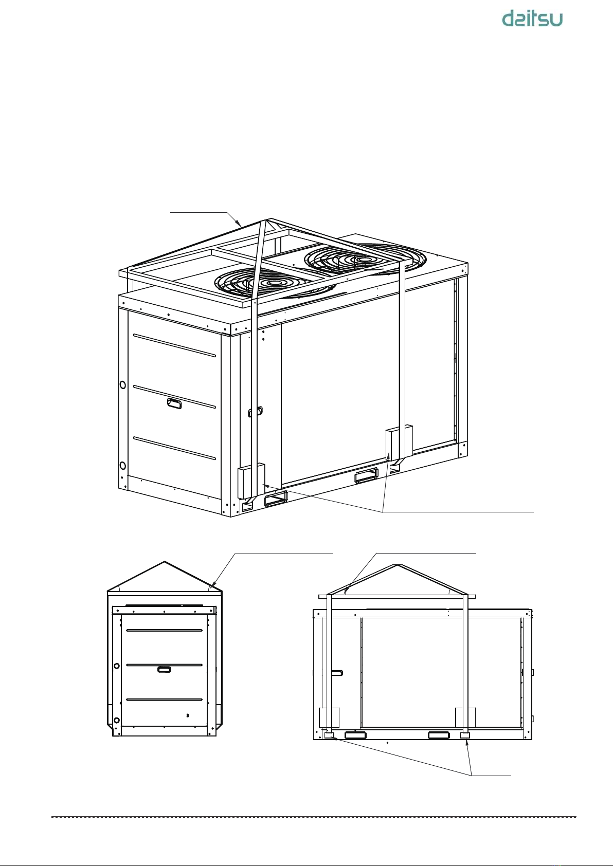
6.4 Installation of damping devices
6.4.1 Damping devices
By means of t installation holes on the steel frame of the unit
base, the unit can be fastened on the foundation through the
spring damper. See Fig.6-7,6-8,6-9(Schematic diagram of
installation dimension of the unit) for details about center
distance of the installation holes. The damper does not go with
the unit, and the user can select the damper according to the
relevant requirements. When the unit is installed on the high
roof or the area sensitive to vibration, please consult the
relevant persons before selecting the damper.
6.4.2 Installation steps of the damper
Step 1. Make sure that the flatness of the concrete foundation
is within ±3mm, and then place the unit on the cushion block.
Step 2. Raise the unit to the height suitable for installation of
the damping device.
Step 3. Remove the clamp nuts of the damper. Place the unit
on the damper, and align the fixing bolt holes of the damper
with the fixing holes on the unit base.
Step 4. Return the clamp nuts of the damper to the fixing holes
on the unit base, and tighten them into the damper.
Step 5. Adjust the operational height of the damper base, and
screw down the leveling bolts. Tighten the bolts by one circle to
ensure equal height adjustment variance of the damper.
Step 6. The lock bolts can be tightened after the correct
operational height is reached.
Damping device
Anchor bolt
Nut
Ferrol
It is recommended that the damper should be fastened on the
foundation with the provided holes. After the unit is placed on the
foundation, the damper connected with the unit should not be
moved, and the central clamp nut is not allowed to be tightened
before the damper sustains load.
Fig. 6-10 Installation of the damper
NOTE
6.5 Installation of device to prevent snow
build-up and strong breeze
(e) Equipment covered with snow
(d) Air inlet blocked by snow
(b) Snow accumulated
on the top plate
(
c) Snow falling on the equipment
(a) Buried in the snow
6.5.1 Measures used to prevent problems caused by
snow
a. Measures to prevent build-up of snow
The base height should be as least the same as the predicted
snow depth in the local area.
b. Lightning protection and snow protection measures
6.5.2 Precautions for designing a snow cover
Monsoon
Outdoor
unit
Base height
Fig. 6-11 Types of problems caused by snow
Fig. 6-12 Snow prevention base height
When installing an air-cooled heat pump chiller in a place with
heavy snow, it is necessary to take snow protection measures to
ensure trouble-free operation of the equipment.
Otherwise, accumulated snow will block the air flow and may cause
equipment problems.
Check the installation site thoroughly; do not install the equipment
under awnings or trees or a place where snow is piled up.
a. To ensure a sufficient air flow required by the air-cooled heat
pump chiller, design a protective cover to make the dust
resistance 1 mm H2O or less lower than the allowable external
static pressure of air-cooled heat pump chiller.
b. The protective cover must be strong enough to withstand the
snow weight and the pressure caused by strong wind and
typhoon.
c. The protective cover must not cause short circuit of air
discharge and suction.
8
Installation Manual___________________________________________________________________________________

7. CONNECTION DRAWING OF PIPELINE SYSTEM
Stop valve Pressure gauge Gate valve
Flexible joint
Y-shaped filter Thermometer Circulating pump one-way valve
Automatic discharge valve
Symbol explanation
Fig.7-1 Connection drawing of pipeline system
Expansion tank
Water replenishing
Dirt discharge valve
Drain valve
Two-way valve
Three-way valve
Terminal
Auxiliary electric heater
unit
unit
Y-type filter,
requiring≥ 40 meshes
This is the water system of standard module.
unit
The ratio of the two - way valves on the terminal shall not exceed 50 percent.
NOTE
9
Installation Manual___________________________________________________________________________________

8. OVERVIEW OF THE UNIT
8.1 Main parts of the uints
Fig. 8-1 main parts of CSAD UiAWP 100 PS
Fig. 8-2 main parts of CSAD UiAWP 200 PS
1
2
8
7
9
4
6
3
5
10
11
1
2
8
7
9
4
6
3
5
10
11
10
Installation Manual___________________________________________________________________________________

NO.
NAME
1 2 3 4 567
Air outlet Top cover
Air inlet
Electric
control box CondenserCompressor Evaporator
NO.
NAME
8 9
Water outlet
Water intlet
1
2
3
4
5
8
7
9
6
11
10
wire controller
Fig. 8-3 main parts of CSAD UiAWP 300 PS
10
water pump
11
11
Installation Manual___________________________________________________________________________________

Door 1 give access to the compartment of water pipes and
water side heat exchanger.
Door 2/3/4 give access to the refrigerating system components and electrical parts
.
8.2 Opening the uint
Door 1
Door 3
Fig. 8-4 Doors of CSAD UiAWP 100 PS
Fig. 8-5 Doors of CSAD UiAWP 200 PS
Door 4
Fig. 8-6 Doors of CSAD UiAWP 300 PS
By means of a detachable service panel, the maintenance personnel can easily access the interior components of the unit.
Door 2
Door 1
Door 1
Door 3 Door 4
Door 2
Door 3 Door 4Door 2
12
Installation Manual___________________________________________________________________________________

Table 8-1
Fig.8-7 CSAD UiAWP 100 PS function diagram
8.3 System diagram
8.3.1 diagram of CSAD UiAWP 100 PS
Fig.8-7 is the function diagram of the CSAD UiAWP 100 PS .
9
21
10
26
12
32
15 35
inlet
outlet
20
19
18
33
36
27
28
1
2
6
8
22
23
7
24
34
37 39
38
14
13
3
4
5
11
16 17
29
30
31 40
25
41
1
40
41
2
22
3
23
4
24
5
25
6
26
7
27
8
28
9
29
10
30
11
31
12
32
13
33
14
34
15
35
16
36
17
37
18
38
19
39
20
21
Plate heat exchanger
Total outlet water temperature sensor
Manual water drain valve
Water flow switch
Unit water outlet temperature sensor
Air purge valve
Safety valve
Unit water inlet temperature sensor
Outdoor ambient temperature sensor
Capillary
Filter
Low pressure switch
Fast oil return solenoid valve
Capillary
Filter
Suction temperature sensor
Pressure gauge joint (low pressure side)
Vapor-liqiud separator
Safty valve
System pressure sensor
Water side antifreeze temperature sensor 1
Water side antifreeze temperature sensor 2
Antifreeze heater of plate heat exchanger
High pressure tank
Filter
Electronic expansion valve
Filter
Coil final outlet temperature sensor
Coiloutlet temperature sensor
Condenser
DC fan
4-way-valve
Oil seperatoraa
Pressure gauge joint(high pressure side)
High pressure switch
Discharge temperature control switch
DC inverter compressor discharge temperature sensor 2
DC inverter compressor discharge temperature sensor 1
Crankcase heater
DC inverter compressor
Water pump
13
Installation Manual___________________________________________________________________________________

Table 8-2
8.3.2 diagram of CSAD UiAWP 200 PS
Fig.8-8 is the function diagram of the CSAD UiAWP 200 PS.
1
25
2
26
3
27
4
28
5
29
6
30
7
31
8
32
9
33
10
34
11
35
12
36
13
37
14
38
15
39
16
40
17
41
18
42
19
43
20
44
21
45
22
46
23
47
48
49
24
Legend
Fig.8-8 CSAD UiAWP 200 PS function diagram
56
12
14
29
15 16
35
18
40
21
34
28
27
48
26
41
44
36
37
1
3
25
33
13
31
32
11
30
43
outlet
42
45 46
47
23
22
20
19
78
24
4
2
9 10
17
38
39
Plate heat exchanger
Water pump
Manual water drain valve
Total outlet water temperature sensor
Water flow switch
Unit water outlet temperature sensor
Air purge valve
Safty valve
Unit water inlet temperature sensor
Outdoor ambient temperature sensor
Capillary
Filter
Fast oil return solenoid valve
Capillary
Filter
Low pressure switch
Suction temperature sensor
Vapor-liqiud separator
Safety valve
Pressure gauge joint (low pressure side)
System pressure sensor
Water side antifreeze temperature sensor 1
Water side antifreeze temperature sensor 2
Antifreeze heater of plate heat exchanger
High pressure tank
Filter
Capillary
One-way valve 3
Electronic expansion valve
Filter
Coil final outlet temperature sensor
Coiloutlet temperature sensor
Condenser
Dc fan 2
Dc fan 1
4-way valve
Oil seperator
High pressure switch
Pressure gauge joint (high pressure side)
One-way valve 2
One-way valve 1
Discharge temperature control switch 2
Discharge temperature control switch 1
Dc inverter compressor discharge temperature sensor 2
Dc inverter compressor discharge temperature sensor 1
Crankcase heater 2
Crankcase heater 1
Dc inverter compressor 2
Dc inverter compressor 1
inlet
49
14
Installation Manual___________________________________________________________________________________

Fig.8-9 CSAD UiAWP 300 PS function diagram
Table 8-3
8.3.3 diagram of CSAD UiAWP 300 PS
Fig.8-9 is the function diagram of the CSAD UiAWP 300 PS.
1
31
2
32
3
33
4
34
5
35
6
36
7
37
8
38
9
39
10
40
11
41
12
42
13
43
14
44
15
45
16
46
17
47
18
48
19
49
20
50
21
51
22
52
23
53
24
54
25
55
26
56
27
57
28
58
29
59
60
61
30
Legend
7
34
12
910
8
13
15
16
41
46
18 19
23
47
21
20 25
30
29
26
28
27
31
32
34
36
37
39
60
38
53
56
45
48
49
17
22
43
14
44
24
55
outlet
54
58
57 59
42
56
11 12
33
35
52
50
51
40
Plate heat exchanger
Manual water drain valve
Total outlet water temperature sensor
Water flow switch
Unit water outlet temperature sensor
Air purge valve
Safty valve
Unit water inlet temperature sensor
Outdoor ambient temperature sensor
Capillary
Filter
Fast oil return solenoid valve
Capillary
Filter
Low pressure switch
Suction temperature sensor
Vapor-liqiud separator
Safety valve
Pressure gauge joint (low pressure side)
System pressure sensor
Water side antifreeze temperature sensor 1
Water side antifreeze temperature sensor 2
Antifreeze heater of plate heat exchanger
Filter
High pressure tank
Electronic expansion valve 2
One-way valve 4
One-way valve 5
Liquid side bypass solenoid valve
Unit for cooling electronic control board
Refrigerant outlet temperature of evi plate heat exchanger
Multifunctional solenoid valve
Refrigerant inlet temperature of evi plate heat exchanger
One-way valve 3
Electronic expansion valve 1
EVI Electronic expansion valve 3
Economizer
Filter
Coil final outlet temperature sensor
Coiloutlet temperature sensor
Condenser
DC fan 2
DC fan 3
DC fan 1
4-way valve
Oil seperator
High pressure switch
Pressure gauge joint (high pressure side)
One-way valve 2
One-way valve 1
Discharge temperature control switch 2
Discharge temperature control switch 1
DC inverter compressor discharge temperature sensor 2
DC inverter compressor discharge temperature sensor 1
Enhanced vapor injection solenoid valve 1
Enhanced vapor injection solenoid valve 2
Crankcase heater 2
Crankcase heater 1
DC inverter compressor 2
DC inverter compressor 1
inlet
61
Water pump
15
Installation Manual___________________________________________________________________________________

Fig. 8-10 Main PCB of CSAD UiAWP 100 PS and CSAD UiAWP 200 PS
8.4 Outdoor unit PCB
MAIN PCB
Label descriptions are given in Table 8-4
1
CN1:Pump 1 connection
2
CN30: Power sequence detection connection
3
S5: DIP switches
4
CN72: Power supply to user interface
5
ENC2: DIP switch for capacity selection
Table 8-4
No. Content
6
7
DSP1: Digital display
8FUS1:Fuse
9
CN43: Power input
10 CN12_1,CN12_2: Solenoid valve (SV4) drive ports
11 IC25: Main control chip
12 CN64: Debug port
13
CN6: Four-way valve drive port
14
CN5,CN5_1: Water side heat exchanger heaters connection
15
CN4,CN4_1: Water flow switch heaters connection
16
CN3,CN3_1: Compressor crankcase heater connections
17
ENC1: DIP switch for address of outdoor units
CN52,CN53: Fan inverter module communication ports
1 2 3 4 5 6 7 89
34
33
32
31
30
29
10
11
12
13
14
15
16
28 27 26 25 24 23 22 21 20 19 18 17
16
Installation Manual___________________________________________________________________________________

Fig. 8-11 Main PCB of CSAD UiAWP 300 PS
Label descriptions are given in Table 8-5
18
19
CN50,CN51: Compressor inverter module communication ports
20
CN55: EXV drive port
21
CN60,CN71: Wired controller communication ports
22
CN24: Outdoor ambient temperature sensor and air side refrigerant outlet temperature
sensor connections
23
CN69: Water side heat exchanger ant-freezing temperature sensor 1, coil final outlet temperature,
discharger temperature sensor 2 and discharge temperature sensor 1 connections.
24
CN31: Air suction temperature sensor, water side heat exchanger anti-freezing temperature
sensor 2, water side heat exchanger water outlet temperature sensor, water side heat exchanger
water inlet temperature sensor and combined water outlet temperature sensor connections.
25
CN40: System pressure sensor connection
26
CN41,CN42: Inverter module temperature 1 and Inverter module temperature sensor 2 connections
temperature sensor 2 connections
27
CN62: AC indicator A and AC indicator B connections
28
CN65:Low pressure switch connection
29
30
CN58,CN59: AC filter board communication ports
31
CN44:Water flow switch, remote function of on/off and cool/heat connections
32
IC10: EEPROM
33
CN21: Remote alarm connection
34
CN19_N: Electric auxiliary heater N line connection
CN47:High pressure switch and discharge temperature switch(es) connections
CN19_L: Electric auxiliary heater N line connection
25
1
27
23
45
67
89
10 11
12
13
14
15
17
18
19
20
2123
24
26
28
29
30
31
32
33
34
35 36
37
38 39
40 41
42
43
44 45
46 47 48
16
22
17
Installation Manual___________________________________________________________________________________

1
2
3
4
5
Detail information
7
8
No.
Table 8-5
10
9
11
12
13
CN30:Input of three-phase four-wire power supply (fault code E1)
Input of transformer, 220-240V AC current. (only valid for the main unit)
Three phases L1, L2 and L3 of power supply should exist simultaneously, and the difference of phase angle should be
120º among them. If the conditions are not met, fault of phase sequence or phase lack may occur, and fault code will
be displayed. When the power supply returns to normal condition, fault is removed. Attention: phase lace and phase
dislocation of power supply are detected only in the early period after the power supply is connected, and they are not
detected while the unit is in operation.
CN12:Quick return oil solenoid valve
CN80:Injection solenoid valve of compressor system B
CN47:Injection solenoid valve of compressor system A
CN5:Water side heat exchanger heaters connection
CN40:Multi-function solenoid valve
6
CN13:Electric of water side heat exchanger heaters connection
CN41:Liquid bypass solenoid valve
CN42:Crankcase heater
CN6:Four-way valve
CN43:Crankcase heater
CN4/CN11:Electric heater of water flow switch
CN14:Three-way valve(hot-water valve)
15
CN83:Pump
1)After receiving start-up instruction, the pump will be started up instantly, and will maintain start-up state always in the
process of operation.
2)In case of refrigerating or heating shutdown, the pump will be shut down 2 minutes after all modules stop operating.
3)In case of shutdown under the pump mode, the pump can be directly shut down.
16
CN83:COMP-STATE,connect with an ac light to indicate the state of the compressor
Attention: the control port value of the pump actually detected is ON/OFF but not 220-230V control power supply,so
special attention should be paid when installing the light.
14
18
Installation Manual___________________________________________________________________________________
This manual suits for next models
2
Table of contents
Popular Inverter manuals by other brands

MQ Power
MQ Power MQ POWER WhisperWatt DCA70USI Operation and parts manual

OutBack Power
OutBack Power GS Load Center Series installation manual

WhisperPower
WhisperPower 12-2000 user manual

Power House
Power House 2000Wi quick start guide

CanadianSolar
CanadianSolar CSI-7K-S22003-E user manual

Go Power
Go Power GP-1750HD GP owner's manual