Microcare 10 Amp User manual
LED MPPT
10 / 20 / 30A
User Manual
Manual Version: LEDMPPT- 2019-1-LION

TABLE OF CONTENTS
IMPORTANT INFORMATION AND SAFTEY INSTRUCTIONS....................................................1
1. INTRODUCTION ...................................................................................................................2
1.1 General Description.........................................................................................................2
1.2 Key Features of the Microcare 10-30A LED MPPT Regulator:........................................2
1.3 Maximum PV Array Sizes ................................................................................................2
2. MPPT OVERVIEW.................................................................................................................3
2.1 LED MPPT Status LED’s .................................................................................................3
2.2 Audible Buzzer.................................................................................................................4
2.3 Reset Button....................................................................................................................4
2.4 Jumper Selection.............................................................................................................4
2.4.1 Low Voltage Load dis-connects:................................................................................4
2.4.2 Battery Type..............................................................................................................4
2.4.3 Daylight Switch off.....................................................................................................4
2.5 Programming ...................................................................................................................5
2.5.1 Low Voltage Cut Out .................................................................................................5
2.5.2 If the daylight switch is selected, the turn on time must also be selected..................5
2.6 Load Connection..............................................................................................................6
2.7 Connecting The Unit........................................................................................................6
2.8 Charging The Batteries....................................................................................................6
2.9 Maximum Panel Voltage (Voc) and (VMP) Per Battery Bank ..........................................6
3. MPPT INSTALLATION ..........................................................................................................7
3.1 MPPT minimum installation clearance distance...............................................................7
7
3.2 MPPT Installation Instructions: ........................................................................................7
4. WIRING INFORMATION .......................................................................................................8
4.1 Cable Connections...........................................................................................................8
4.2 Battery Connection Methods............................................................................................9
4.2.1 Series Connection.....................................................................................................9
4.2.2 Parallel Connection...................................................................................................9
4.2.3 Series and Parallel Connection.................................................................................9
4.3 Basic MPPT Wiring Diagram .........................................................................................10
4.3.1 2 x 60W Panels Connected in Series......................................................................10
4.3.2 2 x 180W Panels Connected In Parallel..................................................................10
4.3.3 2 x 300W Panels Connected in Parallel..................................................................10
4.4 Maintenance and service...............................................................................................10
4.5 Basic LED MPPT Wiring Diagram..................................................................................11
5. LED MPPT SPECIFICATIONS............................................................................................12
6. DESTRIER ELECTRONICS LIMITED CARRY- IN WARRANTY ........................................13

1
IMPORTANT INFORMATION AND SAFTEY INSTRUCTIONS
INFORMATION
Installers should be qualified electricians or technicians
The installation information in the manual is for information purposes only.
The monitoring and operation information in this manual is intended for anyone who needs to
operate the MPPT.
Read the instructions carefully before installing and operating the MPPT.
MPPT connection and installation instructions must be followed.
The unit should only be opened by skilled personal.
Retain the load within in the rating of MPPT to prevent faults.
Keep the MPPT clean and dry.
The MPPT will not operate without batteries.
The MPPT should be installed indoors, in a ventilated and dry area.
Mount the MPPT vertically.
Do not install the MPPT on a rugged or inclined surface.
Do not install the MPPT near water or in damp environments.
Do not install the MPPT where it would be exposed to direct sunlight.
Do not remove the MPPT casing unless the unit needs to be programmed.
Keep the MPPT away from heat emitting sources.
Do not block the MPPT ventilation openings.
Do not leave objects on top of the MPPT
Do not expose the MPPT to corrosive gasses.
Install the MPPT away from any explosive gasses.
Ambient temperature: 0°C –40°C
Sketches are intended for illustrative purposes only and are not intended to provide an
electrical design.
Damage caused by reverse polarity is not covered by warranty.
Do not exceed the MPPT 50 Volt maximum input voltage (Voc) rating.
Refer to your solar module documentation for the worst-case (coldest) module temperature
voltage, it should provide the Vocvs. temperature data.
WARNING
High AC voltage present and is capable of causing severe injury.
.

INTRODUCTION
2
1. INTRODUCTION
1.1 General Description
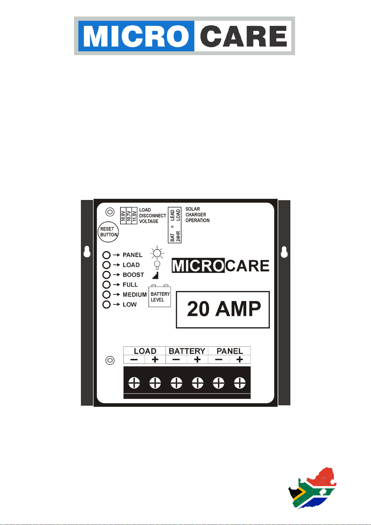
The Microcare Maximum Power Point Tracker (MPPT) Regulator is designed to interface between
the Solar Panel, the Batteries and the Load. The tracker will always find the optimum power point of
the solar panel system to ensure that maximum power is extracted from the solar panel and put into
the batteries.
By using this system up to 30% more power can be extracted from the solar panel than using shunt
or series pass voltage regulators. The Regulator is also able to charge batteries of a lower voltage
than the solar panel. By means of LEDs it will show the status of the system. It also incorporates
various charge modes which will automatically increase the charge level to the batteries when first
starting up or if the battery voltage falls below the minimum volts, the Regulator will read the nominal
battery voltage.
This unit is designed to run on a 12/24V battery set where it will then read the solar panel voltage and
automatically find the optimum power point. The charging, battery values and boost modes are then
automatically adjusted. Via jumpers the load voltage disconnect can be selected, whether the battery
is lead acid or sealed, and whether the unit operates as a normal load shedding unit or as a day/night
switch.
1.2 Key Features of the Microcare 10-30A LED MPPT Regulator:
Automatically measures the battery voltage and then sets up the charge parameters (12-24V)
Operates the Solar Panels at the maximum efficiency
Can improve power extracted from the solar panels by up to 30% over normal shunt/series
pass PWM regulators
LED Display
Temperature controlled Cooling Fan
Selectable low voltage disconnect
24 hour load shed or Street Light mode
Charges batteries by tracking the best power point of the solar panels.
1.3 Maximum PV Array Sizes
The following should be used as a guide to the maximum array size that can be connected to the
MPPT. The current limits to the specified level of the MPPT model so any array larger than these will
damage the MPPT.
Table 1.1: Maximum PV Array Sizes
Maximum Photovoltaic Array Sizes in Watts
Battery Set
10 Amp MPPT
20 Amp MPPT
30 Amp MPPT
12V
120W
240W
360W
24V
240W
480W
720W
MPPT OVERVIEW
3
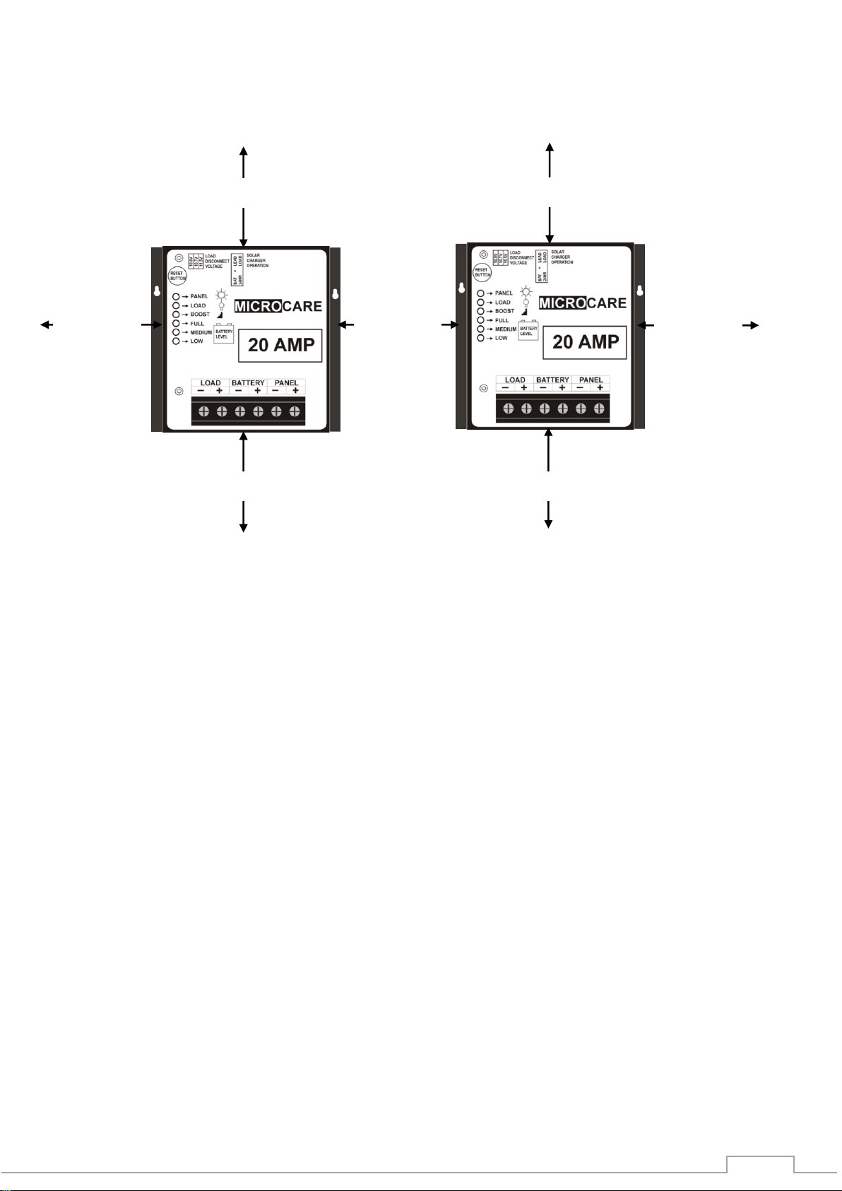
2. MPPT OVERVIEW
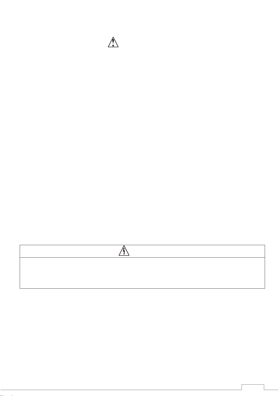
MPPT Front View MPPT Top View
2.1 LED MPPT Status LED’s
2
3
6
PANEL LED
Status
Panel LED Description
Panel
Flashing
No PV Panel Connected or PV Power LOW
Steady ON
PV Connected and Producing power
OFF
Battery Disconnected
LOAD LED
Status
Load LED Description
Load
Steady ON
Load Connected
OFF
No Load Connected
BOOST LED
Status
Boost LED Description
Boost
Steady On
MPPT is in Battery Boost charge mode
Flashing
MPPT is in Battery Float charge Mode
CHARGE LED
Status
Battery State of Charge Level LED Description
Full
Steady ON
Battery fully charged
Med
Steady ON
Battery is half charged
Low
Steady ON
Indicates a low battery condition
MPPT Bottom View

MPPT OVERVIEW
4
2.2 Audible Buzzer
When the batteries are connected for the first time the buzzer will sound:
2 times for a 12V battery set
3 times for a 24V battery set.
The buzzer will beep when the battery voltage has reached within half a Volt of the battery
load disconnect voltage for a 12V system and within 1Volt of load disconnect for a 24V
battery set.
The Buzzer will give 4 beeps twice when the load disconnect is about to trip and 10 times
when the load disconnect has occurred.
2.3 Reset Button
Pushing the reset button cancels the buzzer.
If the unit is in Load Shed the reset button will reset the load but if the voltage is too low then
the load disconnect will operate
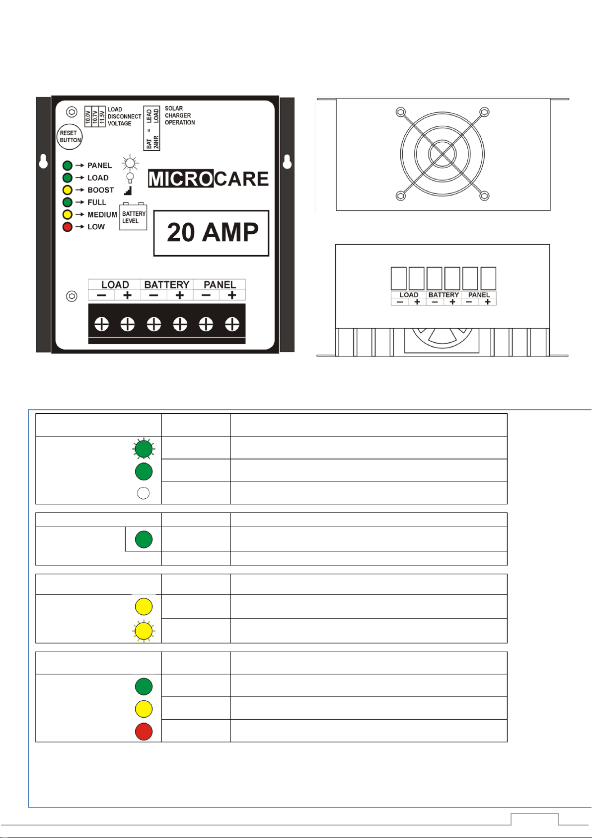
2.4 Jumper Selection
2.4.1 Low Voltage Load dis-connects:
Jumpers 1-3
Battery Bank Voltage
Jumper 1
Jumper 2
Jumper 3
12V Battery Bank
12.1V
12.3V
12.5V
24V Battery Bank
24.2V
24.6V
25.0V
2.4.2 Battery Type
Jumper 4 (Lithium 1 and Lithium 2)
12V Battery Bank charging values
Battery Type
Float Voltage
Boost Voltage
Lithium 1
14.0V
14.0V
Lithium 2
13.9V
14.1V
24 V Battery Bank charging values
Battery Type
Float Voltage
Boost Voltage
Lithium 1
28.0V
28.0V
Lithium 2
27.8V
28.2V
2.4.3 Daylight Switch off
Jumper 5
When the PV Voltage is higher than the battery voltage, the MPPT Regulator will assume
that it is currently day time (Dawn).
When the PV Panel voltage is lower than the battery voltage the MPPT Regulator will
assume that it is night time (Dusk).
In this mode the unit is factory set to switch on at night time and switch OFF during daytime.
A time delay may be introduced to turn on the load either immediately, 0.5 hours, 1.0 hours
or 1.5 hours after Dusk
MPPT OVERVIEW
5
2.5 Programming
To access the Jumpers, disconnect the load, battery and panel wires from the MPPT.
Remove the MPPT cover by removing the 2 screws located on the sides of the MPPT.
Reconnect the Battery wires.
If any of the JUMPERS are changed, it is necessary to press and release the reset button,
the buzzer will sound confirming the change.
2.5.1 Low Voltage Cut Out
Select the desired low cut out voltage by inserting the JUMPER, then push the reset button.
2.5.2 If the daylight switch is selected, the turn on time must also be selected.
Remove the jumper from the 24 hour load position and using the load disconnect voltage
terminal block select 0, 1/2 hour, 1 hour or 1.5 hour. (if no jumper is connected the load will
switch on immediately when the panel voltage goes below the battery bank voltage) Insert
the jumper on the required connection.
To carry out the program, press the reset button until the buzzer beeps 3 times the buzzer
then stays on and the reset button may be released. Replace the jumper for the low voltage
cut out, press the button and the buzzer will beep once.
Day/Nigh Switch Jumper Position
1
2
3
Result
OFF
OFF
OFF
0 Hr Delay
ON
OFF
OFF
0,5 Hr Delay
OFF
ON
OFF
1 Hr Delay
OFF
OFF
ON
1,5 Hr Delay
Select Battery Type:
ON: Lithium 1.
OFF: Lithium2.
Select 24 Hour Run Time
Or day night switching
ON: 24 Hour
OFF: Day/Night
Select Low Voltage Cut-Out
12.1V
2.3V
12.5V
4 5

MPPT OVERVIEW
6
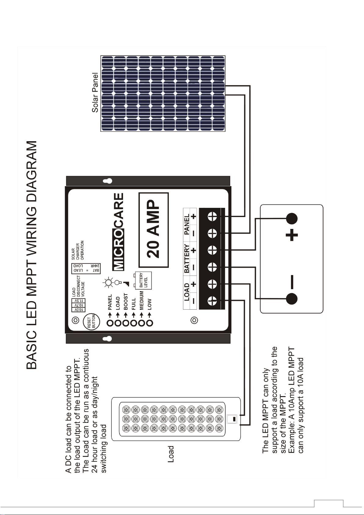
2.6 Load Connection
The Load Connection can only support a Load equal to the MPPT size. Therefore a 10A LED MPPT
can only support a maximum 10 Amp Load.
2.7 Connecting The Unit
Ensure that all cabling used is kept as short as possible as volt drops caused by long cables will
reduce the efficiency of the Tracker. Minimum recommended wire diameter = 4 mm²
First connect the Load and then the Battery.
The LED display will show the Tracker checking the battery. The Medium LED will flash once for a
12V battery and twice for a 24V system. At the same time the buzzer will sound once for a 12V and
twice for a 24V system.
Connect the solar panel. The panel LED will come on if there is sufficient panel power.
The Regulator will now read the solar panel voltage and select the optimum power point. If there is
sufficient power in the solar panel the Tracker will now start charging.
2.8 Charging The Batteries
Boost Mode: The batteries are charged until they reach the boost voltage 14.8V for a 12V battery set
or 29.6V for a 24V battery set. When the batteries reach this level the MPPT will hold this rate for a
minimum of 1/2 hour indicated by the flashing BOOST LED and then switches to Float Mode.
If the batteries fall below the BOOST voltage then the timer is reset i.e. at night or during cloudy days.
This ensures that the batteries are fully Boosted.
FLOAT MODE: Boost light flashes - The batteries are now essentially in trickle charge mode.
2.9 Maximum Panel Voltage (Voc) and (VMP) Per Battery Bank
Suggested Maximum Panel Voltage for a 12V Battery Set
VMP (Max Power Point Voltage) “Min Charge Voltage”
15V
VOC (Max Open Circuit Voltage) “Max Charge Voltage”
24V
Suggested Maximum Panel Voltage for a 24V Battery Set
VMP (Max Power Point Voltage) “Min Charge Voltage”
30V
VOC (Max Open Circuit Voltage) “Max Charge Voltage”
45V
50Voc is the absolute maximum. Systems should be designed for a max of 45Voc due to the
increase in panel voltage due to colder Panel Temperatures. Refer to your solar module
documentation for the worst-case (coldest) module temperature voltage, should provide Voc vs.
temperature data
1
2
3
4
5
7
7
MPPT INSTALLATION
7
3. MPPT INSTALLATION
3.1 MPPT minimum installation clearance distance
Maintain a minimum clearance of 20cm below and above, 10cm on the sides of the MPPT to ensure
unhindered air circulation. Mount the solar charge controller as close as possible to the batteries.
3.2 MPPT Installation Instructions:
Read the installation instructions before installing the MPPT.
The MPPT is designed for indoor applications only.
The mounting position should allow for sufficient ventilation and the minimum clearance
distance between MPPT’s and other objects, trunking as above.
Mount the MPPT at eye level in order to allow the user to read the LED indicators.
The MPPT must be mounted in a vertical position against a solid wall.
Do not install the MPPT in a sealed container.
Do not install the MPPT near water or in damp environments.
Do not install the MPPT where it would be exposed to direct sunlight or near heat.
Do not install the MPPT on a wooden surface. Only install the MPPT on flat concrete,
stone or metal surfaces.
Do not block off the aluminium heat sink and don’t leave objects on top of the MPPT.
Do not expose the MPPT to corrosive battery gases. Corrosion is not covered by
warranty.
MPPT operating environment temperature should not exceed: 0˚C - 40˚C.
Ensure that connecting cables are of adequate size.
100 mm
100 mm
100 mm
200 mm
200 mm
200 mm
200 mm

WIRING INFORMATION
8
4. WIRING INFORMATION
4.1 Cable Connections
The PV (Photo Voltaic) panels should always be connected in the highest voltage configuration, yet
do not exceed the voltages as in section 2.9. The advantage of this is that panel current will always
be at its minimum so that thinner connecting wires may be used which reduces voltage drops with
loading and improves cost efficiency.
The cable length from the batteries to the MPPT should not exceed 3m. The cable lengths
connecting the PV panels to the MPPT should not exceed 30m.
As an example, if there are two 40 volt panels rated at 5 amps each and they are connected in
parallel, then the output voltage would be 40 volts at 10 amps. If they were connected in series the
output would be 80 volts at 5 amps. In both cases the power would be the same but in the parallel
configuration a thicker power cable must be used to reduce the volt drop from the array to the MPPT
as well as from the MPPT to the batteries.
Cable thicknesses listed are recommended thicknesses that have voltage drops accounted for up to
a distance of 3m for connecting the MPPT and the batteries together and the bottom table lists
recommender cable thicknesses for cables connecting the MPPT to the panels up to a distance of
30m.
Table 4.1 Recommended cable size connecting Cables up to 30m
between MPPT and PV panels (Single Stranded Copper
Specifications)
MPPT Type
Cable Core Area
Overall Cable
Diameter
10 Amp
6mm²-10mm²
5.4mm-6.3mm
20 Amp
6mm²-10mm²
5.4mm-6.3mm
30 Amp
10mm²-16mm²
6.3mm-7.5mm
Table 4.2: Recommended cable size connecting Cables up to 3m
between MPPT and batteries. (Single Stranded Copper Specifications)
MPPT Type
Cable Core Area
Cable Core
Diameter
10 Amp
3mm²-4mm²
1.8mm-2.2mm
20 Amp
3mm²-4mm²
1.8mm-2.2mm
30 Amp
6.8mm²-9mm²
2.8mm-3.2mm

WIRING INFORMATION
9
4.2 Battery Connection Methods
4.2.1 Series Connection
12V + 12V = 24V Ah remain at 100 Ah
Series Connection (Voltage increases, amperage stays the same as a single battery)
4.2.2 Parallel Connection
Voltage remains 12V, 100 Ah + 100 Ah = 200 Ah
Parallel Connection (Voltage stays the same as a single battery, amperage increases)
4.2.3 Series and Parallel Connection
Voltage increases to 24 V Ah increases to 200 Ah
2 Strings of batteries in series, connected in parallel
Series/Parallel Connection (both voltage and amperage increase)

WIRING INFORMATION
10
4.3 Basic MPPT Wiring Diagram
4.3.1 2 x 60W Panels Connected in Series
4.3.2 2 x 180W Panels Connected In Parallel
4.3.3 2 x 300W Panels Connected in Parallel
4.4 Maintenance and service
Caution –Risk of Electric Shock.
Batteries may cause electric shock and have a high short-circuit current.
Please take the precautionary measures specified below and any other measures necessary
when working with batteries.
Remove wristwatches, rings and other metal objects.
Only authorized personnel should perform maintenance, inspection, and replacement
operations.
2 x 60 Watt Panels in series
1 x 12 V Battery
1 x 10A LED MPPT
Max 120W panel for a 10A
regulator charging a 12V battery
Max load output 10A
2 x 180 Watt Panels in parallel
1 x 12 V Battery
1 x 30A LED MPPT
Max 360W panel for a 30A
regulator charging a 12 battery
Max load output 30A
2 x 300 Watt Panels in Parallel
2 x 12 V Batteries in series = 24V
1 x 30A LED MPPT
Max total of 720W panel power
when charging a 24V battery
system with a 30A regulator
Max load output 30A
WIRING INFORMATION
11
4.5 Basic LED MPPT Wiring Diagram

LED MPPT SPECIFICATIONS
12
5. LED MPPT SPECIFICATIONS
LED MPPT Type
10A
20A
30A
Maximum Panel
Array Size
12V–120W PV Max
24V-240W PV Max
12V –240W PV Max
24V –480W PV Max
12V –360W PV Max
24V –720W PV Max
Nominal Battery
Voltage
Multi-Voltage 12 or 24VDC (Automatic selection of voltage)
PV Input Voltage
Absolute Maximum 50VOC
Output Load Rating
10A
20A
30A
Charge Algorithm
2-stage Boost/Float
Boost Voltage
Charges to 14.8V (12V) or 29.6V (24V system) for minimum of 3 hours
Float Voltage
13.8V per battery (12V system) or 27.6V (24V system)
Power Conversion
DC/DC Switch Mode
Output Efficiency
>95% Typical @ 14 VDC
Voltage Step Down
Can charge a lower voltage battery from a higher voltage PV array
Status Display
6 LED display: Panel, Load, Boost, Full, Medium, Low
Power Consumption
Less than 1W
Environmental rating
0-40 ºC
Cable Entry
Connector (Max Cable size 16mm)
Dimensions
0.5kg 110mm x 110mm x 70mm

DESTRIER ELECTRONICS LIMITED CARRY- IN WARRANTY
13
6. DESTRIER ELECTRONICS LIMITED CARRY- IN WARRANTY
Destrier Electronics warrants its full range LED MPPT’s against defects in workmanship and
materials, fair wear and tear accepted, for a period of 3 (three) years from the date of
delivery/collection for all equipment and is based on a carry-in basis. Where the installation of the
product makes it impractical to carry-in to our workshops, Destrier Electronics reserves the right to
charge for travel time and kilometres travelled to and from the site where the product is installed.
During this warranty period, Destrier Electronics will, at its own discretion, repair or replace the
defective product free of charge. This warranty will be considered void if the unit has suffered any
physical damage or alteration, either internally or externally, and does not cover damages arising
from improper use such as, but not exclusive to:
•Reverse of battery polarity.
•Inadequate or incorrect connection of the product and/or of its accessories.
•Mechanical shock or deformation.
•Contact with liquid or oxidation by condensation.
•Use in an inappropriate environment (dust, corrosive vapour, humidity, high temperature,
biological infestation.)
•Breakage or damage due to lightning, surges, spikes or other electrical events.
•Connection terminals and screws destroyed or other damage such as overheating due to
insufficient tightening of terminals.
•When considering any electronic breakage except due to lightning, reverse polarity, over-
voltage, etc. the state of the internal control circuitry determines the warranty.
This warranty will not apply where the product has been misused, neglected, improperly installed, or
repaired by anyone else than Destrier Electronics or one of its authorised Qualified Service Partners.
In order to qualify for the warranty, the product must not be disassembled or modified. Repair or
replacement are our sole remedies. Destrier Electronics shall not be liable for damages, whether
direct, incidental, special, or consequential, even caused by negligence or fault. Destrier Electronics
owns all parts removed from repaired products. Destrier Electronics uses new or re-conditioned parts
made by various manufacturers in performing warranty repairs and building replacement products. If
Destrier Electronics repairs or replaces a part of a product, its warranty term is not extended.
Removal of serial nos. may void the warranty.
All remedies and the measure for damages are limited to the above. Destrier Electronics shall in no
event be liable for consequential, incidental, contingent or special damages, even if having been
advised of the probability of such damages. Any and all other warranties expressed or implied arising
by law, course of dealing, course of performance, usage of trade or otherwise, including but not
limited to implied warranties of merchantability and fitness for a particular purpose, are limited in
duration to a period of 3 (three) years from the date of purchase.
Life Support Policy:
As a general policy, Destrier Electronics does not recommend the use of any of its products in life
support applications where failure or malfunction of the Destrier Electronics product can be
reasonably expected to cause failure of the life support device or to significantly affect its safety or
effectiveness.
Destrier Electronics does not recommend the use of any of its products in direct patient care. Destrier
Electronics will not knowingly sell its products for use in such applications unless it receives in writing
assurances satisfactory to Destrier Electronics that the risks of injury or damage have been
minimised, the customer assumes all such risks, and the Liability of Destrier Electronics is adequately
protected under the circumstances.
Caution:
Our products are sensitive. While all care is taken by us to dispatch goods with adequate packaging,
Destrier Electronics is not responsible for any damages caused to products after they have left our
premises.

14
7. REGISTRATION OF MY MICROCARE PRODUCT
Please register your product online at www.microcare/register-my-product
Product Serial Number:
Product Description:
Date Purchased
From whom the product was purchased.
Company Name
Contact Person
Contact Number
E-mail Address
Installation Company Information:
Company Name
Contact Person
Contact Number
E-mail Address
Details of Product Owner
Name & Surname
Address
City & Province
Contact Number
E-mail Address
Date Installed
Microcare: 1st Floor, Neave Industrial Park, Korsten, Port Elizabeth
P.O.Box 7227, Newton Park, 6055
Tel: 041 453 5761, Fax: 041 –453 5763
Website: www.microcare.co.za
Registration by fax: 041 –453 5763
This manual suits for next models
2
Table of contents
Other Microcare Inverter manuals


