Read the full manual before using this product
6
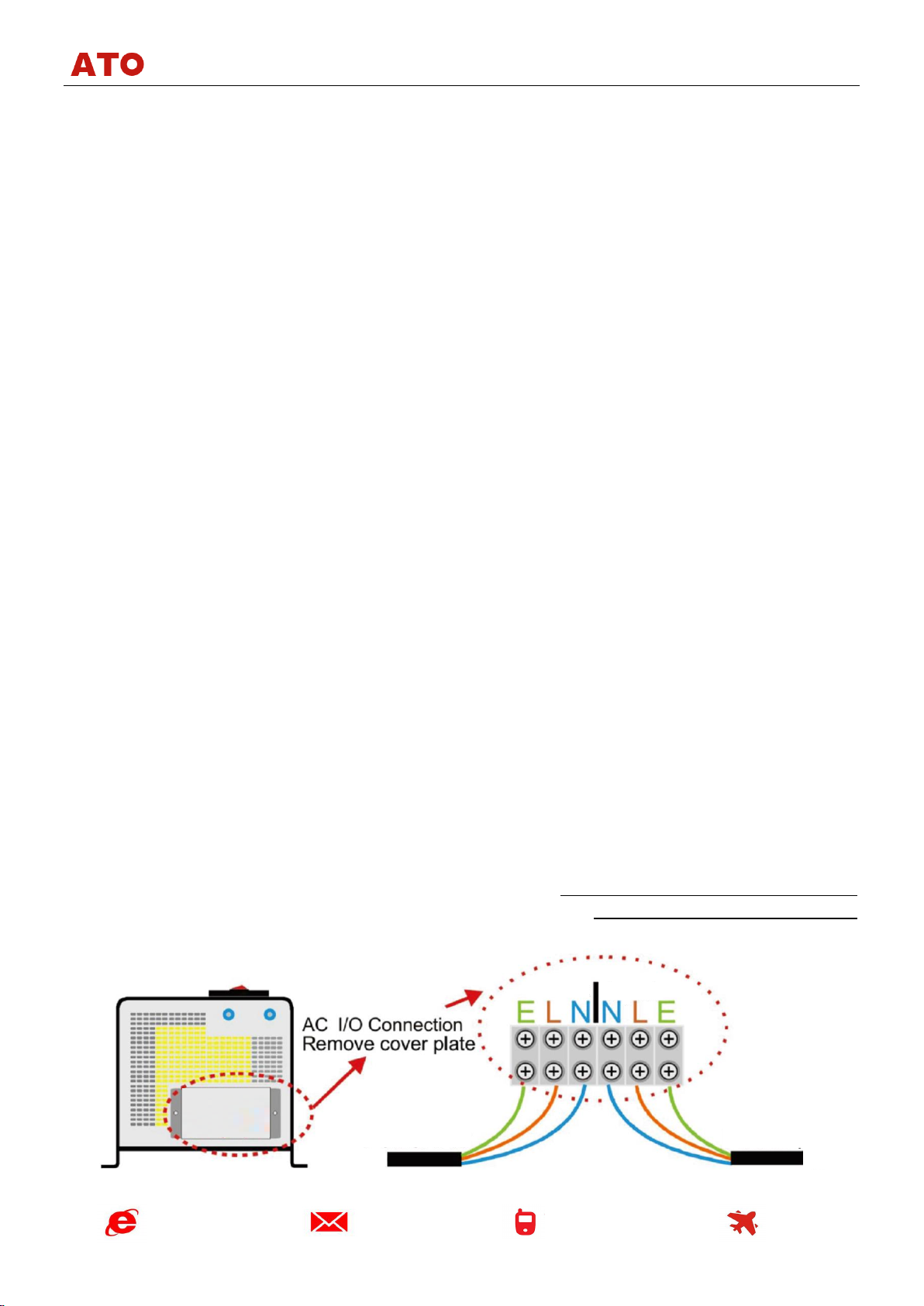
Remove the cover on the AC side of the inverter to access the AC terminals. The inverter has 3
terminals for the AC output (Live, Neutral and Earth) and 3 terminals for the mains AC input (Live,
Neutral and Earth). If your inverter includes an AC output socket, internally this socket is connected to
the AC output terminals.
Note: the order of output and input AC terminals of your inverter might be different
compared to the order shown on the diagram above. Always follow the signs
printed on the inverter casing to identify the correct terminals.
When wiring the AC output of the inverter from the socket or AC output terminals:
•Make sure that all other AC power sources are fully isolated from the circuits to which you
intend to connect the inverter AC output. If you connect the inverter AC output to a circuit which
already has live AC power in it, the inverter will be damaged immediately.
•Use a suitable Residual Current Device (RCD) on the inverter AC output for safety and
protection.
•The inverter has a built-in AC output circuit breaker rated at 30A. If you intend to use the
inverter with smaller AC loads, it is recommended that you install a smaller fuse (3A, 10A, 13A) on
the AC output of the inverter (or use appropriately fused plugs / sockets).
We recommend multi core tri rated AC cable when the inverter is used on a boat or on a vehicle as
this is much safer when vibration is likely. A single solid household AC cable is suitable if the product is
being used as a power source for a house or installation free from vibration.
The inverter also has a 30A circuit breaker installed on the AC input side. If you are planning to use
the inverter with reduced through-power (including “bypass” and battery charging), install a smaller fuse
on the AC input of the inverter, e.g. 3A, 10A or 13A.
When connecting the inverter earth, please note
that the earth wires for AC input and AC output are
connected inside and both are connected to the
inverter case. Use a suitable earthing cable to connect
the inverter casing to the boat’s earth or a bonding
system, vehicle chassis or an earthing rod (for
stationary installations).
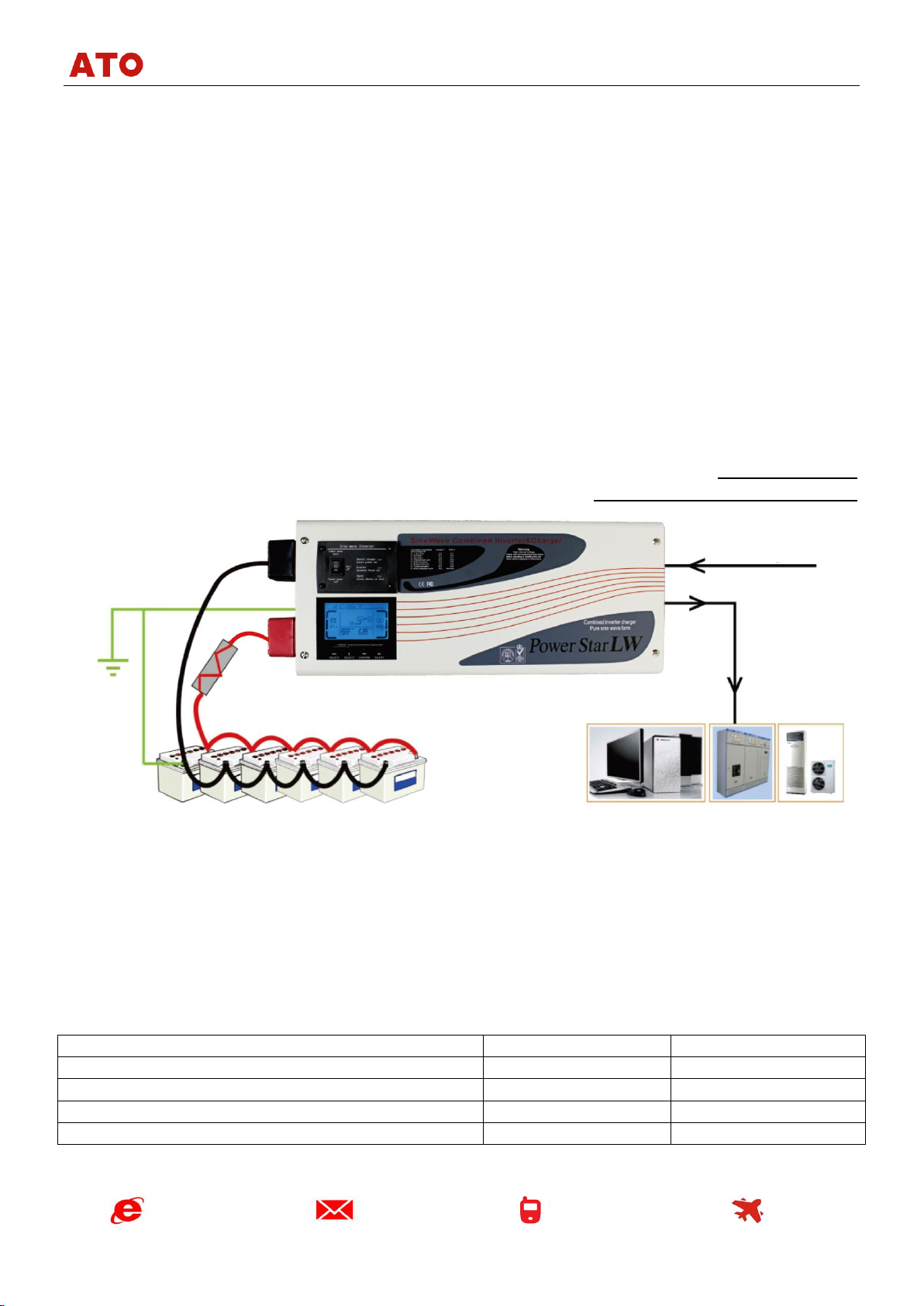
To complete this part of the installation and test the unit: after the inverter has been connected to
the battery bank turn the isolator switch between the inverter and the battery on. Then turn the On/Off
switch of the inverter to “Power Saver Off” position. The LEDs will cycle through the test routine and the
unit should go into the inverter mode and 230V AC should be produced on the output AC terminals.
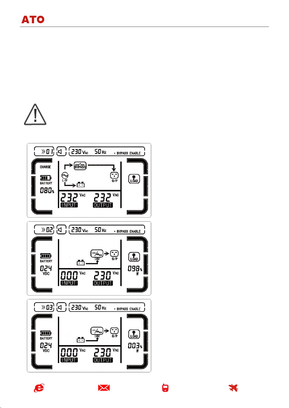
When the AC battery charging or mains input power is required connect the AC input to the
inverter and it will enter the “bypass” mode to start supplying the input AC power to the output AC power
directly. The changeover to mains AC input takes about 10 milliseconds and is hardly noticeable. If the
battery charger is On (default setting) it will start charging the battery bank according to the pre-
programmed battery charging stages (see Appendix 1 for more details).
Installing the remote On/Off control (can be purchased separately)
If you have purchased a remote On/Off switch with 5m cable for your inverter, it can be plugged
into the “Remote control”socket located on the battery terminals side of the inverter.