DAAB DB406 User manual

For the DAAB EP104 automatic control
system with program version 4.06
DAAB DB406 INSTRUCTION MANUAL
FOR THE VFD-EL FREQUENCY CONVERTER
FAAC Nordic AB
BOX 125, SE-284 22 PERSTORP SWEDEN TEL. +46 435 77 95 00 FAX +46 435 77 95 29
www.faac.se
Revision: 2016-0418

2
DAAB OUTPUT CARD DB406 INSTRUCTION MANUAL
2
Installation
1. Disconnect the power to the EP104
2. Screw the DB406 board into place on the spacers on the EP104 using two M3x5 screws.
Connection
e frequency converter being connected to the DB406 must be a DELTA VFD-EL or equivalent. is frequency converter
is based on negative logic. Connect the frequency converter according to the example below which shows a DELTA VFD-EL.
Refer to the diagram on the next page for full details regarding signals and connecting electric motors. e information below
relates to the connections illustrated on the following page.
Ensure that all cables are disconnected from the terminals indicated in the diagram below. Also note the direction in which
the cable is routed through the coil. If this is not correct, the frequency converter and the automatic control unit may be
permanently damaged. After the modication described below, N and T1 will be an input and not an output.
Remove
Remove
Remove
Remove
Remove
Pass the cable
from T1 through
this hole
Pass the cable
from T1 through
this hole

DAAB OUTPUT CARD DB406 INSTRUCTION MANUAL
3
• Connection diagram for 1
motor
Controlpanel
type EP104
A1
T1
N
Frequency converter
R/L1
S/L2
U1
V/T2
U/T1
W/T3
MI1
MI3
DCM
X1
L
N
L
N
IN/OUT (X9)
L1
L2
L3
6
DB406
4
5
3
2
1
MI4
7
8
X28
ST
ST
L1 X13
T1
X10
TR2
L1-CUR1
L1-1 X37

4
DAAB OUTPUT CARD DB406 INSTRUCTION MANUAL
4
• Connection diagram for two
motors

DAAB OUTPUT CARD DB406 INSTRUCTION MANUAL
5
Installing the Delta VFD-EL frequency converter
• Modification of the motor winder
e following criteria must be met in order to use the DAAB motor winder with the frequency converter:
• e limit switch cams must be wider than normal.
• FAAC Nordic AB recommends using a motor with a speed of 2,800 rpm.
• Programming the frequency converter
In start mode F XX (XX = frequency) is displayed. Press the ENTER button to enter programming mode (press the button
once for X-). Select the desired group and press ENTER again – (X-XX) is displayed. Select the desired channel and press
ENTER again – (dX) is displayed. Set the desired value, press ENTER again, when the channel is displayed again press
MODE until the display returns to F XX.
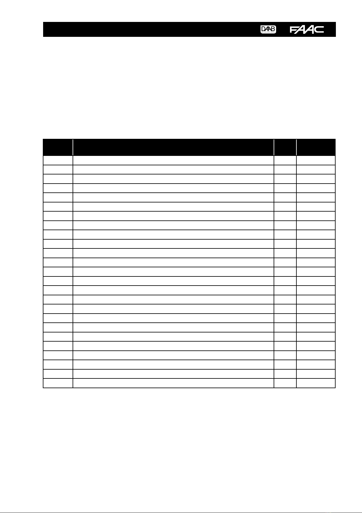
• Channel settings in the frequency converter
Channel
no. Description Fixed
value
Value to be
adjusted
00-03 used to display the output frequency during operation 1
01-00 used to set the maximum output frequency 70 Hz
01-03 used to set the low frequency 7,5 Hz
01-04 used to set the low frequency voltage 60 V
01-05 used to set the start frequency 1,5 Hz
01-06 used to set the start frequency voltage 40 V
01-09 used to set the acceleration time
01-10 Used to dene the retardation time
02-00 used to set the control method 0
02-01 used to set the start method 1
02-02 used to set the type of stop 1
02-04 used to block reversing 1
03-00 used to set the multifunction output 1
03-08 used to set the internal cooling fan 2
04-06 used to set the function of input MI4 2
04-05 used to set the function of input MI3 1
04-04 used to set the function of input MI1 0
* used to set the opening speed
05-00 used to set braking in the opening movement
05-01 used to set the closing speed
05-02 used to set braking in the closing movement
06-01 used to set the over-current protection 170
06-06 used to set the electronic overload relay 2
08-08 used to set the current limit for a speed increase 170
08-15 used to set the number of start attempts before an error message is generated 0
* = is is set using the arrow keys on the display when the frequency converter is in F XX mode. is setting does not use a
channel.
1,5 sek
1,5 sek
50Hz
15Hz
30Hz
15Hz

6
DAAB OUTPUT CARD DB406 INSTRUCTION MANUAL
6
• Channel settings in the EP104 when using an encoder
When a frequency converter is used with the EP104 a load guard cannot be used. For this reason make the following parameter
settings in the automatic control unit:
C201 = 0 - is parameter means that the lower motor protection limit is not tripped when a frequency converter is used.
C202 = 4 - is parameter species that a frequency converter is being used.
C230 = 0.00 - is parameter disables personal protection for motor 1.
C240 = 0.00 - is parameter disables personal protection for motor 2 (if two motors are being controlled).
Channels L114, L115, L124 and L125 specify how many degrees before the end position the motors are to go into low speed
mode. ese channels can be adjusted for optimal operation.
L114 = 45 - is parameter species how many degrees before the open position that the speed decrease of motor 1 is to start.
L115 = 45 - is parameter species how many degrees before the closed position that the speed decrease of motor 1 is to start.
L124 = 45 - is parameter species how many degrees before the open position that the speed decrease of motor 2 is to start.
L125 = 45 - is parameter species how many degrees before the closed position that the speed decrease of motor 2 is to start.
NOTE! Motor protection (C252, C253, C262, C263) must be set to the maximum power consumption reading!
• Channel settings in the EP104 when using mechanical limit switches
When a frequency converter is used with the EP104 a load guard cannot be used. For this reason make the following parameter
settings in the automatic control unit:
C201 = 0 - is parameter means that the lower motor protection limit is not tripped when a frequency converter is used.
C202 = 4 - is parameter species that a frequency converter is being used.
C230 = 0.00 - is parameter disables personal protection for motor 1.
C240 = 0.00 - is parameter disables personal protection for motor 2 (if two motors are being controlled).
Channels C422, C423, C432 and C433 specify how many seconds after the limit position has been activated that the motor
should run at low speed.
C422 = 1.50 - is parameter species a run-on time for the opening movement for motor 1.
C423 = 1.50 - is parameter species a run-on time for the closing movement for motor 1.
C432 = 1.50 - is parameter species a run-on time for the opening movement for motor 2 (if two motors are being
controlled).
C433 = 1.50 - is parameter species a run-on time for the closing movement for motor 2 (if two motors are being controlled).
NOTE! Motor protection (C252, C253, C262, C263) must be set to the maximum power consumption reading!
Note that both switches above the terminal block must be in the upward position!

DAAB OUTPUT CARD DB406 INSTRUCTION MANUAL
7

Table of contents
Popular Media Converter manuals by other brands

Danfoss
Danfoss VLT AutomationDrive operating instructions

ProofVision
ProofVision PV48-BT installation manual

IntesisBox
IntesisBox IBOX-MBS-DALI Installation sheet

StarTech.com
StarTech.com MMC110MMST instruction manual

Transition Networks
Transition Networks E-CX-FRL-03 installation guide

Wisenet
Wisenet SPD-260B installation manual