4
verIfyIng the package contents
• Use & care manual
• Steam barrier with 8 M4.5x20 mounting screws
• 2 glide assemblies with M5x6 mounting screws
• 6 metal shims, 1/16” (1mm)
• Detergent tablets (sample)
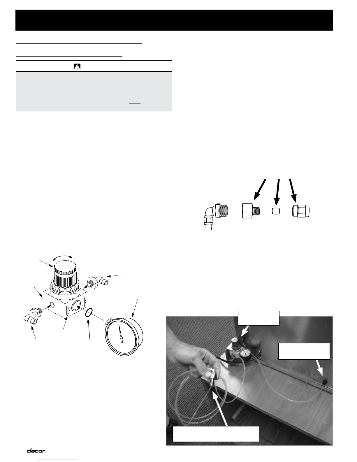
• Pressure regulator (model CM24P-1 only)
• Pressure regulator bracket (model CM24P-1 only)
• Pressure gauge (model CM24P-1 only)
• Regulator gauge O-ring (model CM24P-1 only)
• 3 piece 1/4” hose fitting (model CM24P-1 only)
• Fitting, 1/4-19 BSPP to 1/4” (model CM24P-1 only)
• Teflon tubing (model CM24P-1 only)
• Spare tank O-ring (model CM24T-1 only)
• Spare piston assembly O-ring
• Allen wrench (for grinder adjustment)
• Liquid detergent (sample)
• Anti-liming powder (sample)
• Measuring cup for ground coffee
• Cleaning brush
• Keys (located inside the left slide-out
compartment)
• Flushing system kit (part no. ACFS)
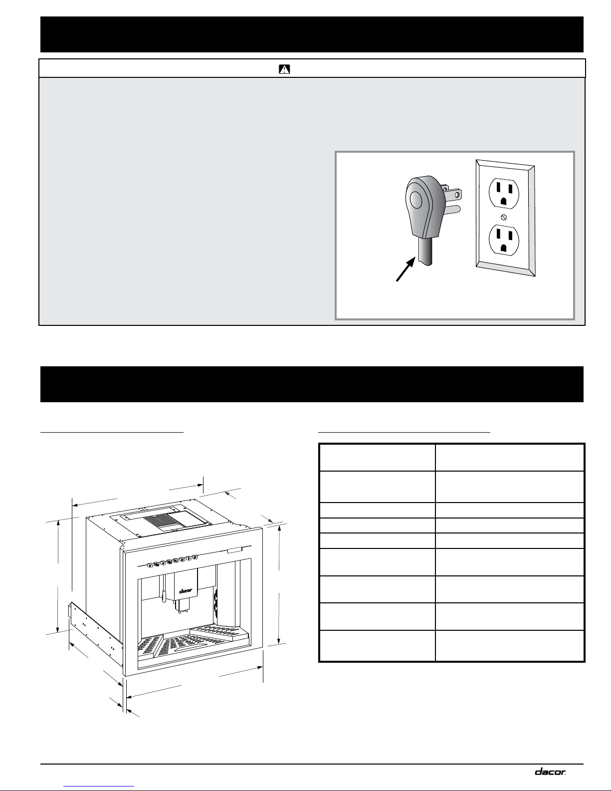
InstallatIon specIfIcatIons
determIne Water hardness
Before installing the coffee system, determine the water
hardness level by doing one of the following:
Use the water hardness test strips included with the
appliance to test the water hardness level of the water
supplied to the building where the coffee system will be
installed. Dip the strip in a cup of water from a faucet
and read the hardness level according to the color key
included with the test strips.
Call the local water company. Ask them for the water
hardness level of the water supplied to the building
where the coffee system will be installed.
For Model CM24T-1 (Tank Model):
If the water hardness level is above four grains per
gallon (4 gpg) you must use filtered water with a
hardness of 4 gpg or less. Do not use distilled water.
If the water hardness level is below 4 gpg, you may
use tap water in the coffee system. Filtered water is
recommended for better taste.
For Model CM24P-1 (Plumbed Model):
If the water hardness is above 4 grains per gallon
(4gpg) contact a water treatment specialist. Have a
water treatment system installed that lowers the water
hardness level to 4 gpg or less.
•
•
•
•
1.
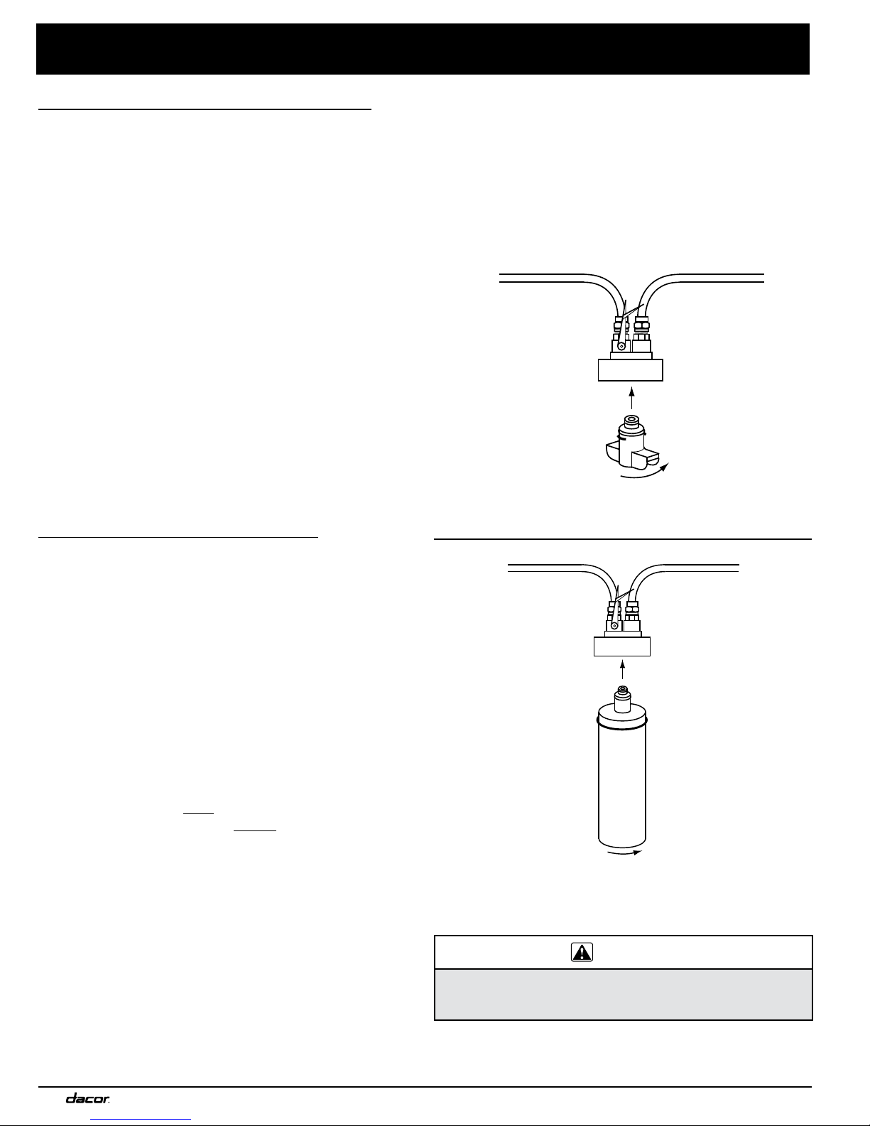
Regardless of the type of water treatment system
installed, you must install the ACFS flushing system
kit included with model CM24P-1. The coffee system
requires periodic decalcification regardless of the water
hardness level. The filter head included in the kit is
required to perform this process for model CM24P-1.
Attach the included bypass module to the filter head.
If the water supply is unfiltered, you may attach the
optional filter cartridge (Dacor P/N ACWF) to the filter
head to improve water taste.
2.
3.
Dacor ACFS flushing system kit installation.
Install for model CM24P-1.
Bypass Module
Filter Head
To coffee system
To house water
supply or whole
house water filter
Installation of optional filter cartridge kit for model
CM24P-1 with a water supply having no existing filter
system.
Optional Filter
Cartridge
(Dacor P/N ACWF)
Filter Head
To coffee system
To house
water supply
CAUTION
Do not use the JT-2 flushing cartridge included with the flushing
system kit in place of a filter. The flushing cartridge is not
designed for long-term use and may leak over time.