manuals.online logo
Brands
  1. Home
  2. •
  3. Brands
  4. •
  5. Dacor
  6. •
  7. Range
  8. •
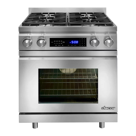
  9. Dacor ER30D Technical manual

Dacor ER30D Technical manual

All specications subject to change without notice. Phone: (800) 793-0093www.dacor.com
PLANNING
GUIDE
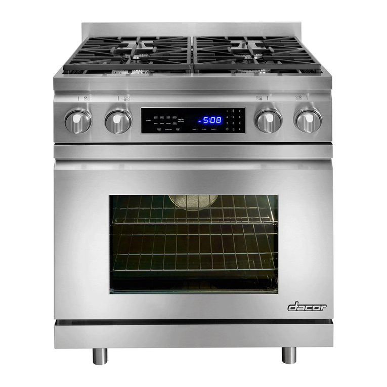
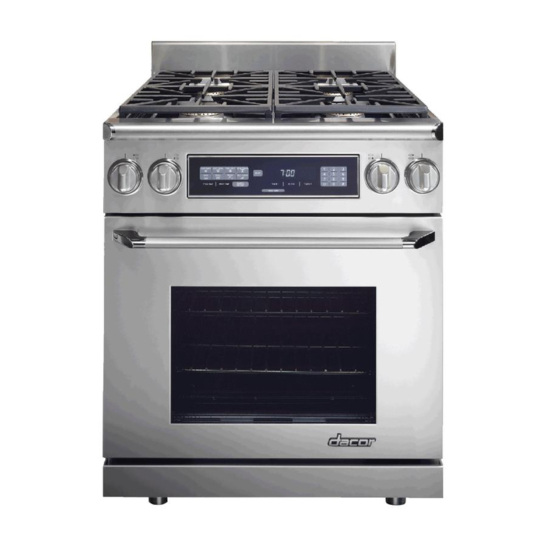
ER30D, ER30DSR
Renaissance®30” Wide
Dual Fuel Ranges
Document # PG05-003 Revised 10/22/14 Page 1/3
ELECTRIC CIRCUIT REQUIREMENTS
Range Model Circuit Required Total Connected
Load
ER30D/ER30DSR 240 Vac, 4-wire*
60 Hz, 30 Amp. 5.6 kW (24.2 Amp.)
◊ The ratings above are for reference only - refer to the range rating
label.
◊ Model ER30D-C is a freestanding range that comes with a factory
installed 4-wire appliance cord and NEMA 14-50P plug. This wiring
configuration is required for freestanding ranges installed in Canada,
although they may be used elsewhere, if local codes permit. The plug
is designed to plug directly into a NEMA 14-50R electrical receptacle
installed by a licensed electrician according to specifications. Do not
modify the factory wiring on model ER30D-C.
NOTE: Models ER30D and ER30D-C are NOT designed for
use with self-rimming installations or downdraft vents.
Use model ER30DSR for self-rimming and downdraft vent
installations.
NOTE:
■Self-rimming models are designed to allow the trim to
overlap the countertop when configured to the dimensions
shown on page 3/3.
■Self-rimming models are not compatible with integral
backguards.
1 9/16”
(4.0 cm)
23 1/8” (58.7 cm)
24 1/8” (61.3 cm)
27 3/16” (69.1 cm)
35 3/4”
(90.8 cm)
to
37 7/8”
(96.2 cm)
28 11/16” (72.9 cm)
46 1/8” (117.2 cm)
Rear of frontpanelto
back of chassis
Rear of frontpanel/oven door
Frontpanel
Frontedge of bullnose
Front of handle
Front of open door
26 3/16” (66.5 cm)
Width at frontpanel:
29 7/8” (75.8 cm)
1 5/16” (3.3 cm) to cooking
surface (top of grates) from
bottom of trim
SELF RIMMING MODEL ER30DSR
SIDE DIMENSIONS
WITH OPTIONAL DOWNDRAFT VENT
TRIM KIT INSTALLED (ATK30SR)
1 1/16” (2.7 cm)
26 5/16” (66.8 cm)
27 5/16” (69.4 cm)
28 13/16” (73.2 cm)
24 1/4” (61.6 cm)
3” (7.6 cm)
Backguard*
6” (15.2 cm)
Backguard**
** Optional
Standard
*
37 7/8”
(96.2 cm)
to
35 3/4”
(90.8 cm)
46 1/4” (117.5 cm)
Width at front panel:
29 7/8” (75.8 cm)
Finished side panel
1 9/16”
(4.0 cm) 1 1/16” (2.7 cm) to cooking
surface (top of grates) from
top of trim
FREESTANDING MODELS ER30D AND ER30D-C 1 9/16”
(4.0 cm)
23 1/8” (58.7 cm)
23 5/8” (60.0 cm)
26 11/16” (67.8 cm)
35 3/4”
(90.8 cm)
to
37 7/8”
(96.2 cm)
28 3/16” (71.6 cm)
45 5/8” (115.9 cm)
Rear of frontpanelto
back of chassis
Rear of frontpanel/oven door
Frontpanel
Frontedge of bullnose
Front of handle
Front of open door
25 11/16” (65.2 cm)
Width at frontpanel:
29 7/8” (75.8 cm)
1 5/16” (3.3 cm) to cooking
surface (top of grates) from
bottom of trim
SELF RIMMING MODEL ER30DSR
SIDE DIMENSIONS
WITH STANDARD TRIM
Product tolerances: ±1/16” (±1.6 mm) unless otherwise stated
WARNING
• Observe all governing codes and ordinances during
planning and installation. Contact your local building
department for further information.
• This appliance must be installed in accordance with
the accompanying installation instructions.
* 4-wire, two 120 Vac hot (L1 and L2), one neutral, one ground
All specications subject to change without notice. Phone: (800) 793-0093www.dacor.com
PLANNING
GUIDE
ER30D, ER30DSR
Renaissance 30” Wide
Dual Fuel Ranges
Document # PG05-003 Revised 10/22/14 Page 2/3
Note 2
F
G
2Cabinet/countertop depth is at discretion of customer but
cabinet face MUST NOT protrude further than rear of front
panel, see product dimensions.
3Vertical distance from range top panel level.
1Vertical to combustible surface from range grate level; if
installing an overhead vent hood, also check the hood
specifications for minimum required clearances.
Non-combustible
surface along
back wall
recommended
10” (25.4 cm) min.
to combustible side
walls above the range
(both sides)
30” (76.2 cm)
min.1
36 1/2”
(92.7 cm)
max.
13” (33.0 cm)
max.4
18” (45.7 cm)
min.3, 4
Suggested
location of
utilities 3
4This specification does not apply for cabinets more
than a horizontal distance of 10” (25.4 cm) from the
edge of the range.
CUT-OUT DIMENSIONS
F G
36” (91.4 cm)*
30” (76.2 cm)** 30 1/16” (91.6 cm)*
* Recommended
** Minimum
Gas and Electrical Service
■The shaded area (diagram bottom left) denotes the location of
the gas inlet and the electrical junction box/receptacle. This is the
recommended location. For replacement purposes, the location of the
existing utilities may be utilized provided they do not interfere with the
sides or rear of the range. Check local building codes for permissible
gas valve and electrical locations.
■An external manual shut-off valve must be installed between the gas
inlet and the range, for the purpose of turning on or shutting off gas to
the appliance.
The installation must allow for the following:
■Access to the gas shut-off valve when the unit is installed.
■Access to the remote circuit breaker panel/fuse box, when the range
is in place.
■The gas supply piping and shut-off valve, and the electrical junction
box/receptacle must be located so they do not interfere with the range
when it is installed.
■The junction box and gas shut off valve must be located so that
the range can be pulled out for service while the appliance remains
connected.
CABINET CUTOUT DIMENSIONS
MODELS ER30D AND ER3OD-C
NOTE: See following page for countertop/cabinet cutout
dimensions for self-rimming installations .
Cabinet tolerances:
+1/16”, (+1.6 mm) -0
GAS SUPPLY PRESSURE REQUIREMENTS*
Gas Type Manifold Pressure Minimum Gas Supply
Pressure
Natural Gas 5” Water Column 6” Water Column
Petroleum (LP) 10” Water Column 11” Water Column
* Maximum input gas supply pressure for all models is 1/2 p.s.i.
GAS - ELECTRICAL ACCESS DIMENSIONS
ABCD E
4 7/8”
(12.4 cm)
21 3/4”
(55.2 cm)
8 5/8”
(21.9 cm)
10 3/16”
(25.9 cm)
7/8”*
(2.2 cm)
* The hole size can be increased to 1 1/8” by removing the conduit bracket
inside the range electrical access box.
B
Gas
inlet
A
C
7/8” (2.2 cm) dia. electrical
connection hole in bottom*
D
Range electrical access,
cover removed
BACK OF RANGE
Product tolerances: ±1/16” (±1.6 mm) unless otherwise stated
All specications subject to change without notice. Phone: (800) 793-0093www.dacor.com
PLANNING
GUIDE
ER30D, ER30DSR
Renaissance 30” Wide
Dual Fuel Ranges
Document # PG05-003 Revised 10/22/14 Page 3/3
ER30DSR J K
without downdraft vent 23 1/2” (59.7 cm) 24” to 25 9/16”
with downdraft vent 24” (61.0 cm) 24 1/2” to 26 1/16”
Cutout tolerances: +1/16” (+1.6 mm), -0 unless otherwise stated
TOP VIEW - MODEL ER30DSR COUNTERTOP/CABINET
CUTOUT DIMENSIONS SELF RIMMING INSTALLATION
Non-combustible
rear wall recommeded
Countertop Height: 35 5/8” (90.5 cm) min., 37 3/8” (94.9 cm) max.
Combustible side
wall above range
countertop opening
29 1/2” (74.9 cm)
30” (76.2 cm)
cabinet opening
below countertop
below countertop
Cabinet face
Notch countertop
overhang to width of
cabinets
1/4” min. (6 mm)
Countertop
overhang
10” min.
(25.4 cm)
both sides
Countertop front
J K
rear wall recommended
Non-combustible
countertop opening
cabinet opening
below countertop
29 1/2” (74.9 cm)
27 1/2” (69.9 cm)
30” (76.2 cm)
2 3/8” (6.0 cm)
Combustible side
wall above range
10” min.
(25.4 cm)
both sides
Countertop Height: 35 5/8” (90.5 cm) min., 37 1/4” (94.6 cm) max.
Notch countertop
overhang to width of
cabinets
3/8” min. (1.0 cm)
Countertop
overhang
below countertop
Cabinet face
downdraft vent opening
J K
Countertop front
TOP VIEW - MODEL ER30DSR COUNTERTOP/CABINET
CUTOUT DIMENSIONS, SELF RIMMING INSTALLATION
WITH DOWNDRAFT VENT (ATK30SR TRIM KIT INSTALLED)
APPROVED DOWNDRAFT VENT: PRV30
Stiffener Cabinet face*
Countertop*
* IMPORTANT: See Countertop/Cabinet Cutout Dimensions
for countertop cutout dimensions.
** IMPORTANT: If optional 3-inch side panels are not installed
cabinet face must be flush with back of control panel.
Back of
control
panel
PRV30
downdraft
ER30DSR range:
ATK30SR trim kit
required for installation
with downdraft vent
3/8” min. (1.0 cm)
space behind
downdraft vent
chassis to clear
stiffener
3/8” min. (1.0 cm)
flat countertop
overhang required
behind cutout
Shown with
optional 3-inch
side panels
installed**
Countertop height:
35 5/8" (90.5 cm) min.
37 1/4” (94.6 cm) max.
28 5/8” (72.7 cm)

Other manuals for ER30D

9

This manual suits for next models

1

Other Dacor Range manuals

Dacor Millennia MRES30 User manual

Dacor

Dacor Millennia MRES30 User manual

Dacor DR30G User manual

Dacor

Dacor DR30G User manual

Dacor HGPR36S User manual

Dacor

Dacor HGPR36S User manual

Dacor Heritage HGER30SNGH User manual

Dacor

Dacor Heritage HGER30SNGH User manual

Dacor DOP36M96GLM User manual

Dacor

Dacor DOP36M96GLM User manual

Dacor Distinctive DR30E User manual

Dacor

Dacor Distinctive DR30E User manual

Dacor Renaissance RR30NFS Technical manual

Dacor

Dacor Renaissance RR30NFS Technical manual

Dacor Epicure EGR30 Technical manual

Dacor

Dacor Epicure EGR30 Technical manual

Dacor Discovery DYRP36DS Technical manual

Dacor

Dacor Discovery DYRP36DS Technical manual

Dacor Epicure ER30DSCH User manual

Dacor

Dacor Epicure ER30DSCH User manual

Dacor ER30D User manual

Dacor

Dacor ER30D User manual

Dacor Epicure ER30DSCH User manual

Dacor

Dacor Epicure ER30DSCH User manual

Dacor Epicure ER36GISCH User manual

Dacor

Dacor Epicure ER36GISCH User manual

Dacor ER30D User manual

Dacor

Dacor ER30D User manual

Dacor DOP48 960G Series User manual

Dacor

Dacor DOP48 960G Series User manual

Dacor Renaissance RNRP30G User manual

Dacor

Dacor Renaissance RNRP30G User manual

Dacor Gas Range Use and care manual

Dacor

Dacor Gas Range Use and care manual

Dacor DOP30 40D Series User manual

Dacor

Dacor DOP30 40D Series User manual

Dacor Discovery DYRP36DC User manual

Dacor

Dacor Discovery DYRP36DC User manual

Dacor EPICURE ER3OD User manual

Dacor

Dacor EPICURE ER3OD User manual

Dacor HDPR30S Quick start guide

Dacor

Dacor HDPR30S Quick start guide

Dacor Renaissance RR30NFS Technical manual

Dacor

Dacor Renaissance RR30NFS Technical manual

Dacor Epicure EGR30 User manual

Dacor

Dacor Epicure EGR30 User manual

Dacor Renaissance RNRP30GSNG User manual

Dacor

Dacor Renaissance RNRP30GSNG User manual

Popular Range manuals by other brands

Whirlpool RF110AXS Use and care guide

Whirlpool

Whirlpool RF110AXS Use and care guide

Whirlpool SF3020EKQ3 Use and care guide

Whirlpool

Whirlpool SF3020EKQ3 Use and care guide

Samsung NE594R0ABBB/AA user manual

Samsung

Samsung NE594R0ABBB/AA user manual

Frigidaire GLGC30S9EBA Factory parts catalog

Frigidaire

Frigidaire GLGC30S9EBA Factory parts catalog

Frigidaire FEF355E Factory parts catalog

Frigidaire

Frigidaire FEF355E Factory parts catalog

Viking VGIC306-4B Series Specification sheet

Viking

Viking VGIC306-4B Series Specification sheet

Whirlpool GW399LXUB05 Use & care guide

Whirlpool

Whirlpool GW399LXUB05 Use & care guide

Hotpoint RB792SRSA Dimension Guide

Hotpoint

Hotpoint RB792SRSA Dimension Guide

Fisher & Paykel RGV3-485GD user guide

Fisher & Paykel

Fisher & Paykel RGV3-485GD user guide

Frigidaire FEF352F supplementary guide

Frigidaire

Frigidaire FEF352F supplementary guide

Jenn-Air JGS8750BDB installation instructions

Jenn-Air

Jenn-Air JGS8750BDB installation instructions

Whirlpool Gold GFE461LV Dimensions and installation information

Whirlpool

Whirlpool Gold GFE461LV Dimensions and installation information

Kenmore 790.3262 Series Use & care guide

Kenmore

Kenmore 790.3262 Series Use & care guide

GE JGBS14PCDWW Dimensions and installation information

GE

GE JGBS14PCDWW Dimensions and installation information

Kenmore 66575172302 installation instructions

Kenmore

Kenmore 66575172302 installation instructions

Modular 70/40 PCG Series Installation - use - maintenance

Modular

Modular 70/40 PCG Series Installation - use - maintenance

EMPERO EMP.7KG021 instruction manual

EMPERO

EMPERO EMP.7KG021 instruction manual

Frigidaire FEF455WFBE Use & care manual

Frigidaire

Frigidaire FEF455WFBE Use & care manual

manuals.online logo
manuals.online logoBrands
  • About & Mission
  • Contact us
  • Privacy Policy
  • Terms and Conditions

Copyright 2025 Manuals.Online. All Rights Reserved.