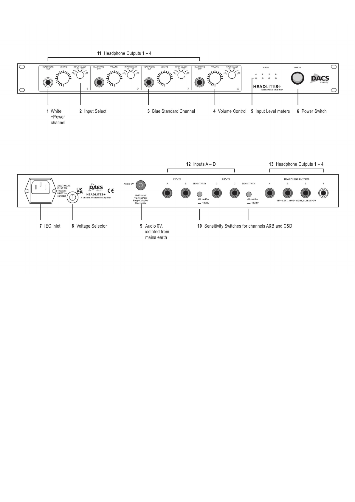
Dacs HeadLite 3+ User manual

HeadLite 3+
Four channel headphone amplifier
User Guide

Instructions for use and installation
Welcome
At DACS we are very pleased that you have chosen to purchase one of our prod-
ucts. Fully assembled and tested in the UK this HeadLite 3+ will give you years of
exemplary service. We’re so confident in the quality of our products that our stand-
ard warranty is double the statutory one year and by registering you can extend it
for another year. Please visit our web site for details—www.dacs-audio.com.
If you have any suggestions or comments about this product please call or e-mail
us with your thoughts.
Thank you.
Introduction
HeadLite 3+ is a four input four output headphone amplifier with a six position
source selector switch for each amplifier. It is designed to be as flexible as possible
without introducing needless complexities.
THAT InGenius® balanced inputs ensure very low distortion transformer like rejec-
tion of interference and very good frequency response. The input connectors are
three pole ’TRS’ jack sockets; they will also accept unbalanced signals on 2 pole
jacks.
Its standard outputs can drive virtually any headphones; with the +Power module
fitted to Channel 1 even the most demanding low impedance high power head-
phones are driven cleanly. The outputs are also designed to drive down long lines
to cubicles with no loss of quality. The unit is compatible with -10dBV and +4dBu
inputs (see - “10 Sensitivity Switches”). The +Power module as well as driving
power hungry headphones will drive multiple headphones - we have used up to 6
pairs of 400 Ohm headphones and experienced no level drop. Additional +Power
modules can be fitted to other channels at the time of order or retrofitted any time
after purchase. Please speak to your retailer or direct to us for details.
DACS LTD Stonehills Shields Road PELAW Gateshead Tyne and Wear NE10 0HW UK
Tel: +44 (0) 191 4382500
www.dacs-audio.com sales@dacs-audio.com

HeadLite 3+
1 +Power channel 3 Standard Channel
The +Power Channel provides around 450mW into 50Ω headphones and the Standard Channel
around 150mW into 50Ω (see Power Output in Specifications). The HeadLite3+ comes with one
+Power channel and three Standard but can have +Power modules fitted to the other channels.
Connections
The headphone outputs are on three pole ¼” jacks tip=left ring=right sleeve=0V. The front and
rear outputs for each headphone amplifier are connected in parallel. The output circuitry is de-
signed to drive down long lines with minimal high frequency loss. If two or more pairs of head-
phones are to be driven by one output they should be of the same type and impedance. If they
are different (eg. low and high impedance) power sharing will not be even and their volume may
be significantly different.
2 Input Select
With up to four inputs connected to the unit decide which headphone amplifier output you wish to
use. To select the input(s) you wish to listen to rotate the selector switch to the appropriate point:
AB means inputs A and B on the Left and Right output respectively; AA means input A on both
Left and Right BB means input B on both Left and Right etc. Plug your headphones in and adjust
the volume to an acceptable level.
4 Volume Control
The HEADPHONE VOLUME control adjusts the signal level going to the amplifier. This control
allows independent volume control of each amplifier’s output.

7 IEC Inlet
The unit will accept 240 VAC and 110/115 VAC mains supplies selected as described below.
12 Inputs A-D
Use TRS ¼” jack plugs for balanced sources two pole jacks for unbalanced. Input impedance is
10kΩ. If no connector is plugged in the inputs are shorted to 0V; if connected to a patchbay it is
advisable to normalise them at the patch bay to avoid the potential for interference pick up. In
case of accidental patching of phantom power in OB or studio applications we have included
overvoltage protection on the inputs so 48V cannot damage the input stage.
5 Input Level Meters
These tri colour LED meters indicate the level on the 4 busses feeding the headphone amplifiers.
They are calibrated as follows:
Green starts to glow at -24duB and is fully on at -8dBu to 0dBu
Orange starts at 0dBu and is fully on at +10dBu to +16dBu
Red starts at +16dBu and is fully on over +18dBu
For optimum performance operate HEADLITE 3+ at 0dBu to +10dBu.
6 Power
This switches the power on and off and is illuminated when the unit is on. If the switch does not
illuminate the fuse may be blown. The unit comes with a spare fuse in the fuse carrier (T1A).
Clarity HEADLITE 3+ is fitted with an ultra quiet regulated linear power supply.
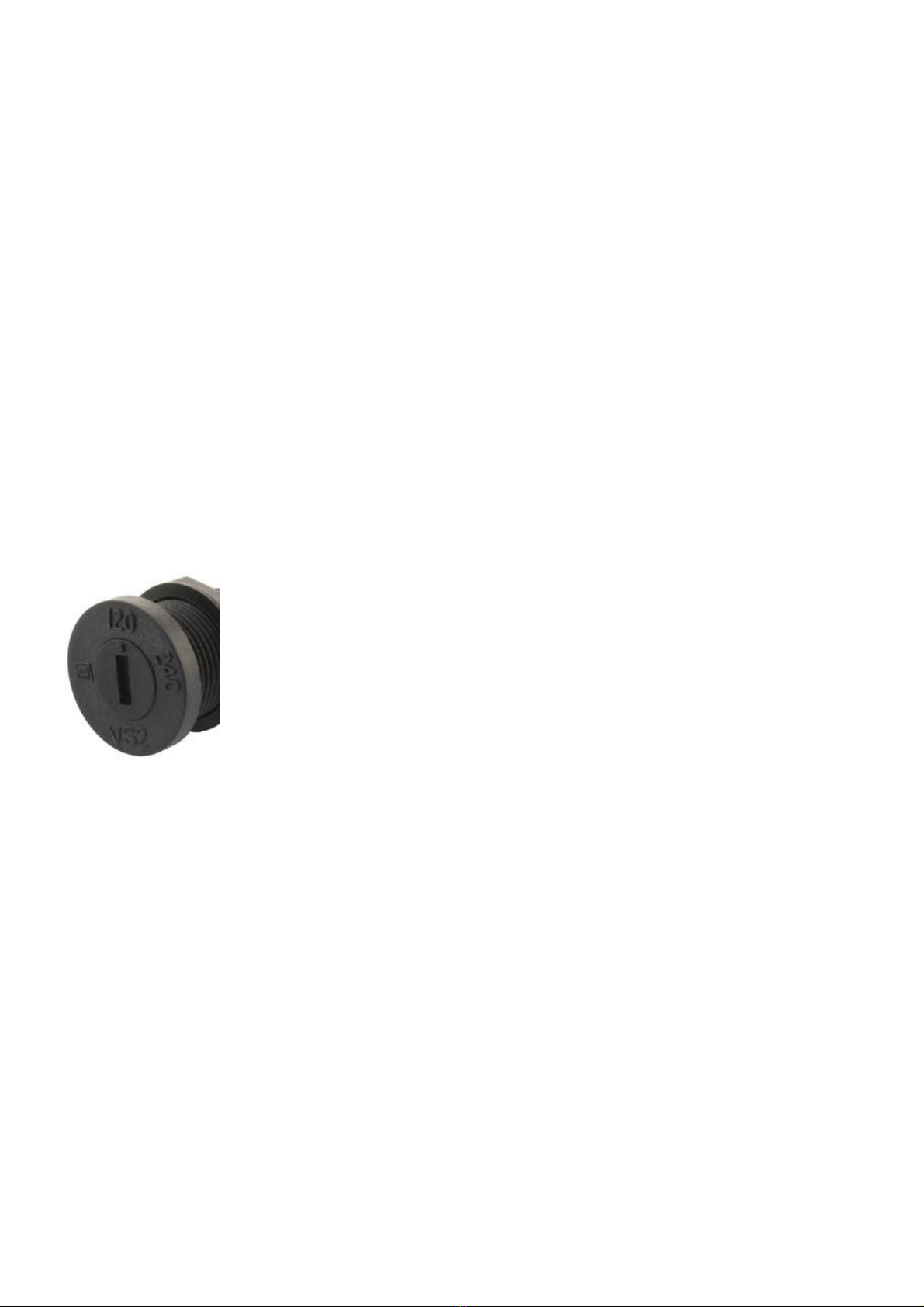
8 Voltage Selector
Using a flat head screwdriver insert the tip into the slot and turn it to point to either 240 (for
240/230VAC) or 120 (for 110/115VAC).
9 Audio 0V
The Audio 0V is separate from the mains earth. This separation allows unbalanced operation with
a large measure of immunity to hum problems since the amplifier is not referenced to or connect-
ed to any earth other than the signal source. The mains earth is connected to the case of the de-
vice. If you wish to connect the signal earth to the mains earth or a technical earth this may be
done by running a wire from the 0V terminal. This connection should only be made by quali-
fied personnel, if it is necessary. If in doubt please call us.
10 Sensitivity Switches
On the rear panel there are sensitivity switches for channels A&B and C&D. This allows user se-
lection of input sensitivity as an operational control; -10dB adds 12dB gain to the incoming signal
(-10dBV to +4dBu) while +4dBu adds no gain.

11/13 Headphone Outputs 1-4
Headphone outputs 1-4 on the front are the same as those on the rear. It is fine to plug in to both
front and rear simultaneously as long as the headphones are the same. The amplifier section can
deliver up to 450mW RMS per channel and has a fixed gain of 20dB. The volume potentiometer
varies the input level to the amplifier stage. Too high an input level will reduce the useful control
over the output volume since it will have to be set very low to ensure that the output does not
clip. To adjust Input Sensitivity see 10 above.
Specifications
Noise floor: <-100dBu (120dB below peak)
Maximum input level: +18dBu
Dynamic range: >114dB
THD+N 20Hz to 22kHz +10dBu into 600R: <.00087%
Frequency response: 5Hz to 30kHz ± .2dB
CMRR >84dB 50Hz to 20kHz
Slew rate: >20V/λs
Max inter channel phase difference: 20Hz .03 deg 1kHz .03 deg 10kHz .30 deg
20kHz .55 deg
Crosstalk: <-95dB
Table of contents
Other Dacs Amplifier manuals