Daewoo Solar 420LC-V User manual

Return to Master Table of Contents
1
HYDRAULICS

Page 1
Hydraulic System Troubleshooting, Testing and
Adjustment
Return to Master Table of Contents
1
HYDRAULIC SYSTEM
TROUBLESHOOTING,
TESTING AND
ADJUSTMENT
HYDRAULIC SYSTEMTROUBLESHOOTING,TESTING AND ADJUSTMENT
CAUTION!
Follow all safety recommendations and safe shop practices outlined in the front of this manual
or those contained within this section.
Always use tools and equipment that is in good working order.
Use lifting and hoisting equipment capable of safely handling load.
Remember, that ultimately safety is your own personal responsibility.
MODEL SERIAL NUMBER RANGE
Solar 420LC-V 1001 and Up
Solar 470LC-V 1001 and Up
Copyright 2001 Daewoo
November 2001

Page 2 Hydraulic System Troubleshooting, Testing and
Adjustment
Return to Master Table of Contents
TABLE OF CONTENTS
Hydraulic System - General Notes.................................................................4
Hydraulic Schematic.......................................................................................5
General Notes.........................................................................................5
Operation of Working Components................................................................6
Boom Operating Circuit...........................................................................6
Boom Up Circuit......................................................................................6
Boom Down Circuit .................................................................................6
Arm Operating Circuit .............................................................................7
Arm Crowd Circuit...................................................................................7
Arm Dump Circuit....................................................................................7
Bucket Operating Circuit.........................................................................8
Bucket Crowd Circuit...............................................................................8
Bucket Dump Circuit ...............................................................................8
Swing Operating Circuit ..........................................................................8
Right Swing Operating Circuit.................................................................9
Left Swing Operating Circuit ...................................................................9
Swing Relief Valve and Make-upValve ...................................................9
Travel Operating Circuit...........................................................................9
Forward Travel Circuit............................................................................10
Reverse Travel Circuit............................................................................10
Procedural Troubleshooting Baseline Recommendations............................11
Initial Checks andTests to Establish Operating Condition of the Excavator
11
Pilot Pressure...............................................................................................12
Adjustment and Testing.........................................................................12
Power Mode Valve........................................................................................13
Current Signal and Hydraulic Pressure Adjustments............................13
Boom/Front Priority Valve.............................................................................14
Control Valve Pressure and Current Adjustments.................................14
Pressure Up Valve........................................................................................15
Checks and Adjustments ......................................................................15
Pump Input Power Control ...........................................................................17

Page 3
Hydraulic System Troubleshooting, Testing and
Adjustment
Return to Master Table of Contents
Pump Regulator Adjustment.................................................................17
Flow Meter and Flow Meter Kit Installation and Testing...............................20
Swing System Troubleshooting ....................................................................22
Precautions/Initial Checks.....................................................................22
Swing Relief Valve Checking and Adjustment.......................................22
Troubleshooting - Swing Gearbox ................................................................24
Troubleshooting - Hydraulic Problems..........................................................25
Troubleshooting - ControlValve....................................................................27
Troubleshooting - Travel Control Valve..........................................................28
Troubleshooting - Joystick Control Valve......................................................29

Page 4 Hydraulic System Troubleshooting, Testing and
Adjustment
Return to Master Table of Contents
HYDRAULIC SYSTEM - GENERAL NOTES
The hydraulic system has several improvements over conventional hydraulic systems - including cross-
sensing total horsepower control - to maximize output efficiency.
The system features an electronically controlled output optimization system, which allows the operator to
choose between three, distinctly different power modes: high-output/rapid cycling maximum-speed power
mode, low fuel consumption/low-noise light duty power mode, and a standard power mode for most types
of general operation offering some of the advantages of each of the other two power modes.
Electronic management of hydraulic control valves assists in optimizing the application speed and overall
operator control of hydraulic actuators and functions.
2
3
3
2
1
HAOF420L
Figure 1 Pattern of Drawing (Solar 470LC-V)

Page 5
Hydraulic System Troubleshooting, Testing and
Adjustment
Return to Master Table of Contents
HYDRAULIC SCHEMATIC
The hydraulic schematic(s) is available in the "Hydraulic and Electrcial Schematic Shop Manual." This
manual is a collection of diagrams and schematics for a number of models.
GENERAL NOTES
When refering to the schematic, refer to the following items:
• As shown in the schematic, the main pump assembly is driven by the engine. Mechanical
energy is converted to hydraulic power, generating the required hydraulic flow which drives the
system. Two main pumps (a right side pump and a left side pump) make up the main pump
assembly.
• Hydraulic output from the right side pump is transmitted to the right side of the control valve.
Output from the left side pump is transmitted to the valve spools on the left side of the control
valve.Hydraulic output from the pilot pump is used to control the pump and to operate pilot and
solenoid valves.
• The right half of the hydraulic control valve, supplied by the right pump in the pump assembly,
operates valve spools for right travel, swing, boom2, and arm1 functions.The amount of oil flow
to the actuators at the output end of each of those circuits is regulated through the movement of
each individual valve spool.
• The left half of the hydraulic control valve, fed by the left pump in the pump assembly, has
control spools for left travel, bucket, boom1 and arm2 operation.
• Two-stage operation is a feature of boom and arm function. All of these circuits can be operated
using the output of only one half of the hydraulic pump assembly (one pump or the other), or –
since both halves of the control valve have a spool and available circuit for these functions – the
output of both pumps can be combined, allowing higher speed operation. Boom up, arm crowd
and dumping functions can operate in any one of the two available power modes – the standard
or general duty mode, the high speed/rapid cycling mode.
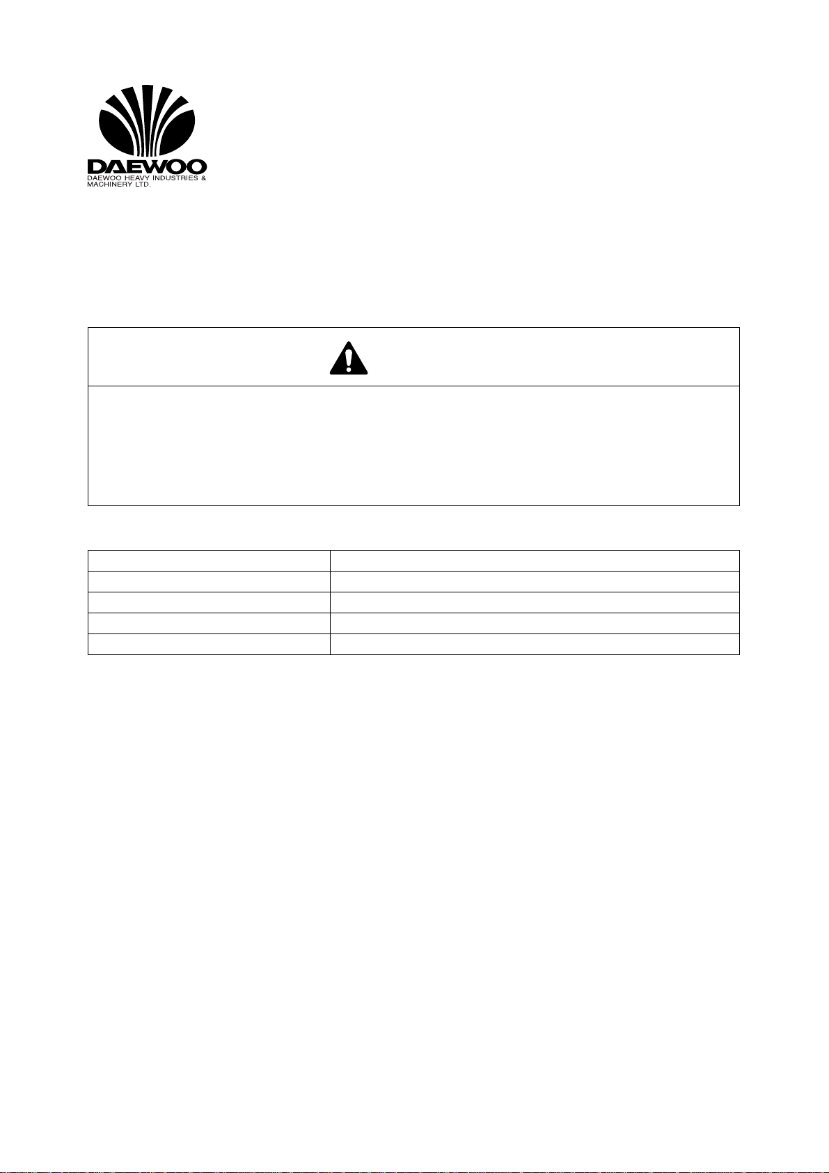
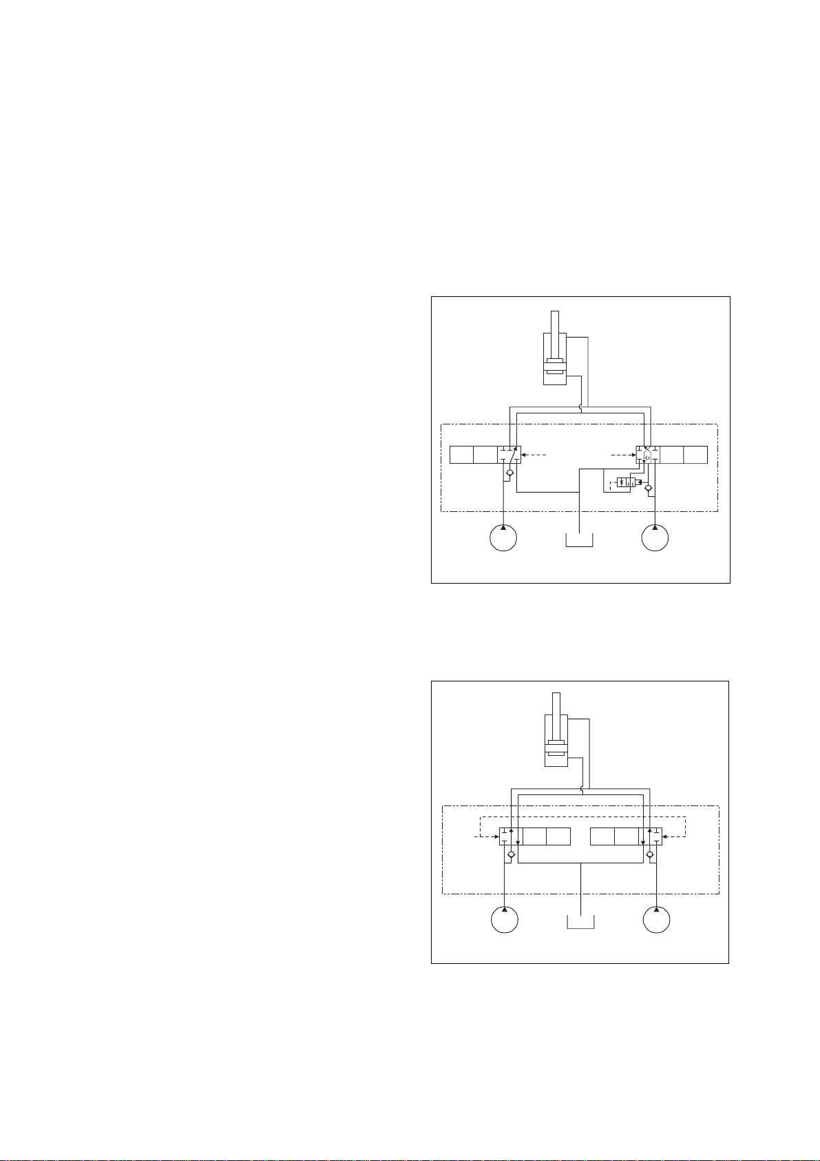
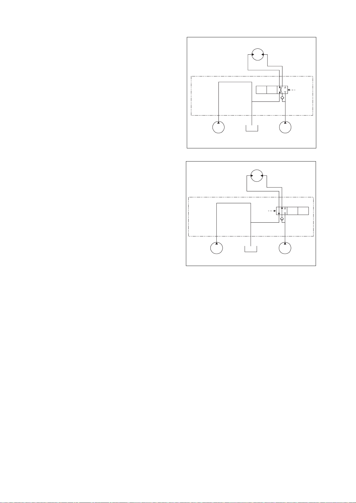
• Whenever the right travel or left travel control spools are shifted, output from the main pump
assembly passes through the center joint to one or both of the axial piston motors driving the
side frame crawler tracks. A pilot valve connected to the swash plate of each travel motor
changes motor capacity (and output) in direct proportion to the position of the travel switch
selected by the operator.
• The hydraulic reservoir return line and the pilot circuit both have 10 micron full flow filters.The
disposable elements in these two canister-type filters trap and remove impurities from the oil in
the system. An 80 mesh, 177 micron reservoir intake strainer also helps maintain system
cleanliness and should be cleaned each time hydraulic fluid is drained and replaced. An oil
cooler in the hydraulic system helps maintain the operating temperature of the system at
approximately 50°C (122°F).
• The arm cylinder operating circuit includes anti-vacuum valves which protect the hydraulic
system from vacuum that could result from external shocks or other unusual conditions. Boom,
Arm, and Bucket cylinder circuit are also protected by overload relief valves. Whenever high
pressure is generated as a result of a shock or overload, excess pressure is dumped to the
reservoir return circuit through the relief valve.
• A selection valve in the travel circuit can be used to provide constant high torque/low speed
travel, or variable speed/variable torque output for travel.To prevent sliding during simultaneous
travel and boom/arm/bucket operation, select the high torque/low speed travel position.

Page 6 Hydraulic System Troubleshooting, Testing and
Adjustment
Return to Master Table of Contents
OPERATION OFWORKING COMPONENTS
BOOM OPERATING CIRCUIT
The boom operating circuit includes the right and left main hydraulic pumps (both halves of the main pump
assembly), both sides of the control valve and the boom cylinder.The circuit operates in boom down mode
through the first shift position and through the second shift position in boom up mode. Overload relief
valves set at 360 kg/cm
2
. (5,112 psi) protect the hydraulic system from damage as a result of overloads or
shocks to the boom. Additional protection - to prevent cavitation of the cylinder - is provided by a make-up
valve and reservoir return circuit, which ensures that the volume of oil going to the cylinder will not exceed
the volume of oil coming out.
BOOM UP CIRCUIT
When you pull the boom control lever backward,
the right side pilot valve generates secondary
boom up pilot pressure that is transmitted to the
BOOM1 and BOOM2 spools of the control valve
simultaneously. When secondary pilot pressure
reaches 7 - 10 kg/cm
2
(100 - 142 psi), boom
spools open and oil from both pumps goes to
the boom cylinder.
BOOM DOWN CIRCUIT
When the boom control lever is pushed forward,
the right side pilot valve generates secondary
boom down pilot pressure that is transmitted
only to BOOM1 spool of the valve. When
secondary pilot pressure reaches 7 - 10 kg/cm
2
(100 - 142 psi), the BOOM1 spool opens so that
oil from only one pump (PUMP(L)) assembly
goes to the boom cylinder for boom lowering.
BOOM
CYLINDER
BOOM UP
PILOT
BOOM1 BOOM2
PUMP(L) PUMP(R)
ATS0750L
Figure 2
BOOM
CYLINDER
BOOM1BOOM2
PUMP(L)PUMP(R)
ATS0760L
BOOM DOWN
PILOT
Figure 3

Page 7
Hydraulic System Troubleshooting, Testing and
Adjustment
Return to Master Table of Contents
ARM OPERATING CIRCUIT
The arm operating circuit includes both the right and left hydraulic main pumps, the both sides of the
control valve, arm regen. valve, and the arm cylinder. The circuit can be operated in the two-stage speed
control mode which works through both halves of the control valve and doubles the volume of oil flowing to
the cylinder.
Overload relief valves set at 360 kg/cm
2
(5,112 psi) have been installed at the crowd and dump cylinder
ports on ARM1 side of the control valve to protect the circuit and system components from possible
damage caused by shocks or overload pressure.additional protection - to prevent cavitation of the cylinder
- is provided by a make-up valve and reservoir return circuit, which ensures that the volume of oil going to
the cylinder will not exceed the volume of oil coming out.
ARM CROWD CIRCUIT
When the arm control lever is put in the crowd
mode, the left side pilot valve generates
secondary pressure that is transmitted to the
ARM1 and ARM2 of the control valve
simultaneously.
When secondary pilot pressure reaches 7 - 10
kg/cm
2
(100 - 142 psi), the arm control valve
spool on the ARM1 and ARM2 spools open.
Output flow from both pumps are directed to the
arm cylinder.
When working in the arm crowd mode, under
certain conditions, arm cylinder could be forced
out by the weight of the arm and bucket itself. At
this time insufficient oil flow to the cylinder could
lead to cavitation in the cylinder head and/or
surging or irregular movement.This is prevented
by a regeneration valve attached to the control
valve which maintains the balance between oil
flowing into the cylinder and oil flowing out.
ARM DUMP CIRCUIT
When the arm control lever is put in "dump"
mode, the left side pilot valve generates
secondary pilot pressure that goes to both
ARM1 and ARM2 the control valve
simultaneously.
When pilot pressure reaches 7 - 10 kg/cm
2
(100
- 142 psi), the control spools open allowing oil
from PUMP(L) and PUMP(R) to flow to the arm
cylinder.
ARM
CYLINDER
ARM2ARM1
PUMP(L)PUMP(R)
ATS0770L
ARM CROWD
PILOT
REGEN V/V
Figure 4
ARM
CYLINDER
ARM2 ARM1
PUMP(L) PUMP(R)
ATS0780L
ARM DUMP
PILOT
Figure 5

Page 8 Hydraulic System Troubleshooting, Testing and
Adjustment
Return to Master Table of Contents
BUCKET OPERATING CIRCUIT
The bucket operating circuit includes the right and left main pumps, the both sides of the control valve and
the bucket cylinder. 360 kg/cm
2
(5,112 psi) overload relief valves located at crowd and dump cylinder ports
on BUCKET of the control valve protect the circuit and its components from damage.
BUCKET CROWD CIRCUIT
When the bucket control lever is placed in the
crowd position, the right side pilot valve
generates secondary bucket crowd pilot
pressure that is transmitted to BUCKET and BC
spool of the control valve.When secondary pilot
pressure reaches 7 - 10 kg/cm
2
(100 - 142 psi),
the BUCKET and BC spools open so that oil
from both pumps goes to the bucket cylinder.
BUCKET DUMP CIRCUIT
When the bucket control lever is put in the dump
mode, the right side pilot valve generates
secondary bucket dump pilot pressure that is
transmitted to BUCKET spool of the control
valve.When secondary pilot pressure reaches 7
- 10 kg/cm
2
(100 - 142 psi), the bucket spool
opens so that oil form PUMP(L) goes to the
bucket cylinder.
SWING OPERATING CIRCUIT
The swing operating circuit consists of the right main pump in the pump assembly, the right half of the
control valve and the swing motor. To keep the upper works from coasting when the swing control is in
neutral, an electrical sensor in the control circuit activates a valve to automatically engage a mechanical
brake.
BUCKET
CYLINDER
BUCKET
PUMP(L) PUMP(R)
ATS0790L
BUCKET
CROWD
PILOT
BC
Figure 6
BUCKET
CYLINDER
BUCKET
PUMP(L) PUMP(R)
ATS0800L
BUCKET
DUMP
PILOT
Figure 7

Page 9
Hydraulic System Troubleshooting, Testing and
Adjustment
Return to Master Table of Contents
RIGHT SWING OPERATING CIRCUIT
When the swing control lever is pushed to the
right swing position, pilot pressure from the left
side pilot valve is directed to SWING spool of
the control valve. Output flow from PUMP(R) is
goes to the swing motor.
LEFT SWING OPERATING CIRCUIT
When the swing control lever is pushed to the
left swing position, pilot pressure from the left
side pilot valve is directed to SWING spool of
the control valve moves in the opposite direction
and output flow from the PUMP(R) is goes to the
swing motor.
SWING RELIEFVALVE AND MAKE-UP VALVE
Whenever the spool is shifted to the neutral mode during swing operation, the possibility exists that surge
pressure in the circuit - caused by inertial momentum of the upper works and correspondingly reduced
pressure at the opposite motor port - could produce cavitation in the circuit.To keep that from happening, a
relief valve is installed in the swing motor and a large-capacity make-up valve is connected to the entrance
port of the hydraulic reservoir, helping maintain acceptable pressures on both sides of the circuit.
NOTE:
Relief Valve Setting Pressure:
S420LC-V : 270.0 kg/cm
2
(3,840 psi)
S470LC-V : 280.0 kg/cm
2
(3,980 psi)
TRAVEL OPERATING CIRCUIT
Output flow from both halves of the pump assembly is directed to the right and left travel motors through
the right and left sides of the control valve, and the upper works center joint.
SWING MOTOR
SWING
SWING
RIGHT
PILOT
PUMP(L)PUMP(R)
ATS0810L
Figure 8
SWING MOTOR
SWING
SWING
LEFT
PILOT
PUMP(L) PUMP(R)
ATS0820L
Figure 9

Page 10 Hydraulic System Troubleshooting, Testing and
Adjustment
Return to Master Table of Contents
FORWARDTRAVEL CIRCUIT
When the right and left travel control levers are
pushed forward, output from both of the main
pumps is directed through the TRAVEL (R) and
TRAVEL (L) spools on the control valve, through
the upper works center joint, to the travel motors
on each side of the machine.
REVERSETRAVEL CIRCUIT
When the right and left travel control levers are
pushed backward, output from both main pumps
is directed through the TRAVEL (R) and
TRAVEL (L) spools on the control valve, through
the upper works center joint, to the travel
motors.
TRAVEL
MOTOR(L) TRAVEL
MOTOR(R)
CENTER JOINT
TRAVEL(L) TRAVEL(R)
L.TRAVEL
FORWARD
PILOT
R.TRAVEL
FORWARD
PILOT
PUMP(L) PUMP(R)
ATS0830L
Figure 10
TRAVEL
MOTOR(L) TRAVEL
MOTOR(R)
CENTER JOINT
TRAVEL(L) TRAVEL(R)
L.TRAVEL
BACKWARD
PILOT
R.TRAVEL
BACKWARD
PILOT
PUMP(L) PUMP(R)
ATS0840L
Figure 11

Page 11
Hydraulic System Troubleshooting, Testing and
Adjustment
Return to Master Table of Contents
PROCEDURALTROUBLESHOOTING BASELINE
RECOMMENDATIONS
INITIAL CHECKS ANDTESTS TO ESTABLISH OPERATING CONDITION OF THE EXCAVATOR
Triage Summary
An excavator that fails to deliver designed performance should be checked for the following:
• Hydraulic flow, first, and
• Hydraulic pressure, afterwards, in a specified order of priority through different points of the
system.
To verify adequate available hydraulic flow, before any other tests are performed through the circuit:
Check engine operation -
• at 2,150 RPM with no load
• at 2,000 RPM stall load
If engine RPM drops excessively with a load or fails to surpass rated speed (1,900 RPM), performance
problems may be due to inadequate hydraulic flow caused by lagging rotational speed.
NOTE:
Verify actual flow on the excavator against rated performance, with a flow meter.
If engine tests meet specifications and adequate torque and horsepower are available at the pump drive
flex coupling, pull out the electrical tray under the operator’s seat to inspect the self-diagnostic display.
If the EPOS trouble code display is clear, check hydraulic functions in the following sequence:
• Pilot pressure
• Negacon, negative control pressure
• Main relief pressure (front and rear pump)
• Swing pressure
• Port relief pressure (individual control functions; crowd, bucket, boom, travel)
• Power boost circuit
• Standard performance tests; cylinder speed, hydraulic motor (travel and swing) speed, cylinder
oil-tightness "permissible drift" test
NOTE:
System specification performance tests of individual activator function are determined by
flow rate through the component or circuit, not the control pressure or system pressure
available to the actuator. Poor flow through the individual circuit may indicate that the
component is worn beyond tolerance limits, while all other hydraulic functions are
adequate.
IMPORTANT
It is suggested that the troubleshooter maintain the testing sequence of the preceding list.
Checks and adjustments nearer the middle or the end of the list may depend on adequate
functioning of systems tested nearer the top of the list.

Page 12 Hydraulic System Troubleshooting, Testing and
Adjustment
Return to Master Table of Contents
PILOT PRESSURE
ADJUSTMENT ANDTESTING
Vent hydraulic pressure from the reservoir before breaking the seal on fittings to install two in-line "t-style"
adapters and test gauges (60 bar/1,000 psi) at the gear pump outlet port, and at the joystick control valve
pilot line.
Start the engine and turn the engine speed control dial to the maximum setting. After the excavator has
been operated long enough to reach normal operating temperature, back off the engine control dial to
minimum rated RPM speed.With all controls in neutral, make sure the left console control stand is locked
in the down (operating) position and check pressure at the gear pump outlet port and at the joystick.
If gear pump pressure is outside the tolerance specified in the table, adjust gear pump relief pressure by
loosening the lock nut and turning the set screw in (clockwise) to increase pressure, or turning it out to
decrease it.
NOTE:
Be aware that serial number changes and variation in the joystick assemblies used on
different excavators could produce slight change in actual performance characteristics.
Comparison of part numbers to serial numbers stamped on your assembly may be
required, if questions or doubt exists.
WARNING!
This procedure should be done with two people.To reduce the chance of accident or unintended
start-up, one person should remain at the operator’s control stand while checks and
adjustments are made.
IMPORTANT
Top off the hydraulic fluid reservoir if there is any measurable loss of hydraulic oil during test
gauge and adapter fitting installation.
Engine RPM Pilot Pressure @ Pump Pilot Pressure - Joystick
Minimum Speed Setting (full left) on
Speed Control Dial 40 ±5 bar
(580 ±73 psi) 40 ±5 bar
(580 ±73 psi)

Page 13
Hydraulic System Troubleshooting, Testing and
Adjustment
Return to Master Table of Contents
POWER MODEVALVE
CURRENT SIGNAL AND HYDRAULIC PRESSURE ADJUSTMENTS
The electromagnetic pressure proportioning control (EPPR) "power mode" valve is located on the
underside of the pumps (not visible in the harness connections drawing, because it is underneath the
assembly), near the engine/pump flexible coupling, adjacent to the pump return line. To test and adjust
power shift current and pressure through the power mode valve a multi-lead jumper harness is required.
The jumper harness (which is available through Daewoo After Sales Service, or could be spliced together
from commonly available, purchased parts) has extra leads so that a VOM meter can be connected to the
circuit.
To set up the testing equipment, turn off the engine and disconnect the single electrical lead from the
power mode valve. Attach the jumper harness to the terminal on the valve, connect the test leads of the
multimeter to the extra leads on the harness and reconnect the valve electrical lead.
Vent the lever on top of the hydraulic tank to relieve pressure and connect an in-line "t-style" adapter to the
valve pressure port. Install a 60 bar/870 psi (1,000 psi) test gauge in the adapter.
Restart the engine and increase engine RPM by turning the speed control to the maximum speed setting.
Warm up the engine and hydraulic system until hydraulic oil temperature is at least 45°C (113°F). Select
Power Mode on the Instrument Panel. Check current readings (in milliamps) on the VOM meter and
hydraulic pressure gauge readings and make sure both conform to the values in the table below.
NOTE:
If recorded values do not conform to the specified current or pressure in the table, back off
the lock nut on the end of the valve, turn the adjusting screw 1/4 turn and re-check current
and pressure. Repeat adjustment as required to obtain specified performance and
retighten the valve lock nut.
WARNING!
This procedure should be done with two people.To reduce the chance of accident or unintended
start-up, one person should remain at the operator’s control stand while checks and
adjustments are made.
Mode Engine RPM Current Pressure
Power Mode High Idle: 2,150 RPM 600 ±20 mA 1.5 bar
(22 psi)
Standard Mode High Idle 2,150 RPM 0 mA 18 bar (261 psi)

Page 14 Hydraulic System Troubleshooting, Testing and
Adjustment
Return to Master Table of Contents
BOOM/FRONT PRIORITY VALVE
CONTROLVALVE PRESSURE AND CURRENT ADJUSTMENTS
The front priority control valves are located inside the compartment behind the cabin.
The same jumper harness used for testing the power mode (EPOS) control valve is used to test these two
valves.Turn off the engine, disconnect either of the electrical leads and connect the test equipment to that
side of the valve.An in-line "t-style" gauge adapter can be used to connect a 60 bar/870 psi (1,000 psi) test
gauge to the outlet (pressure) side of the valve. Set the engine control speed dial to maximum and warm
up the engine to at least 45°C (113°F) before making any tests.
NOTE:
Vent air from the hydraulic system before installing test equipment. Use the lever on the
reservoir, while the engine is running. Pour clean replacement fluid back into the system if
excessive fluid was lost.
Operate the swing and boom simultaneously. Measure signal current and hydraulic pressure through the
valve and record the highest and lowest values. Reset the work mode control to "digging" mode, and then
to "trenching" mode and repeat the same tests.
NOTE:
If recorded values do not conform to the specified current or pressure in the table, readjust
as required.
WARNING!
This procedure should be done with two people.To reduce the chance of accident or unintended
start-up, one person should remain at the operator’s control stand while checks and
adjustments are made.
VALVE FUNCTION
DIGGING MODE
TRENCHING MODE
VOLTAGE PRESSURE VOLTAGE PRESSURE
Front Priority
0 V 40 bar
(580 psi) 20 - 30 V 0 bar
(0 psi)
HAOB730L
HAOB740L

Page 15
Hydraulic System Troubleshooting, Testing and
Adjustment
Return to Master Table of Contents
PRESSURE UPVALVE
CHECKS AND ADJUSTMENTS
Vent hydraulic pressure from the reservoir to install an in-line "t-style" adapter and test gauge (60 bar/1,000
psi) at the pilot pump signal port relief valve outlet.
Start the engine and turn the engine speed dial to maximum. When normal operating temperature is
reached,
• Check pilot pressure and readjust it, if required;
• Select the Instrument Panel rear pump "pressure display";
• Select Power Mode;
• Stall the boom cylinder (towards the extend side);
• Read rear pump pressure on the Instrument Panel display.
Repeat all tests with and without "pressure up" selected through the console rocker switch and joystick
button.
If the 2-stage main relief valve was not set correctly and main relief high-stage pressure ("pressure up") is
outside the tolerance range, begin valve adjustment by loosening the outside (widest diameter) lock nut on
the relief valve.Turn the adjusting screw clockwise to increase pressure, or counterclockwise to decrease
it. Pressure must be 350 bars (5075 psi), or up to 10 bars (145 psi) higher.
Because one adjustment can affect the other, check low-stage main relief pressure by repeating the
cylinder stall test without "pressure up." Readjust standard relief pressure by turning the inner-most
(smallest diameter) screw clockwise to increase the setting, or counterclockwise to decrease it. Pressure
should be at least 320 bars (4,641 psi), but less than 325 bars (4,714 psi).
WARNING!
This procedure should be done with two people.To reduce the chance of accident or unintended
start-up, one person should remain at the operator’s control stand while checks and
adjustments are made.
IMPORTANT
Pressure adjustments and checks cannot be made if pilot pressure is outside the specified
range. Refer to the pilot pump adjustment procedure if required, then proceed with any
necessary adjustments to main relief pressure settings.
Power Mode Operation Main Pressure and
Tolerance Pilot Pressure and
Tolerance
Mode Neutral, No Operation 20 - 40 bar
(290 - 580 psi) 30 bar + 10 bar
(435 psi + 145 psi)
Mode Cylinder Stall 320 bar + 5 bar
(4,641 psi + 75 psi) 30 bar + 10 bar
(435 psi + 145 psi)
Mode W/
pressure Up Cylinder Stall 350 bar + 10 bar
5,075 psi + 145 psi 30 bar + 10 bar
(435 psi + 145 psi)

Page 16 Hydraulic System Troubleshooting, Testing and
Adjustment
Return to Master Table of Contents
NOTE:
The electrical pressure up (power boost) solenoid valve located alongside the swing
priority solenoid and arm speed control solenoid, in compartment rear of the operator’s
cab, must be operating correctly, or pressure tests and further adjustments cannot be
made.

Page 17
Hydraulic System Troubleshooting, Testing and
Adjustment
Return to Master Table of Contents
PUMP INPUT POWER CONTROL
PUMP REGULATOR ADJUSTMENT
To perform these adjustments accurately the use of a flow meter is strongly recommended, as is consulting
the factory (before starting work) to validate the need for making regulator adjustments. Vent hydraulic
pressure from the reservoir before breaking the seal on fittings to install the flow meter kit. (Refer to the
"Flow meter Installation and Testing" procedure.)
Use a scribe or other permanent marker to identify a reference point on adjusting screws with a
corresponding reference on the body of the valve.The adjustment process affects a complex balance and
could require some time to complete.If adjustment has to be interrupted or postponed, reference marks at
the adjustment point allow immediate restoration of original performance.
This adjustment procedure is normally performed:
• If the engine is being consistently overloaded (and engine troubleshooting shows engine
performance to be at or above rated output);
• If reduced cylinder speed and diminished work performance provide an indication that rated,
maximum pump flow may not be available (and all other troubleshooting gives no indication of
other flaws or hydraulic system defects);
• If pump output is out of balance and one pump is failing to keep up with the output flow of the
other.
To check pump imbalance without a flow meter, travel the excavator forward on flat, level terrain. If the
machine veers off despite neutral control input and even, balanced track adjustment, the pump which
supplies output to the track frame toward which the excavator is veering is weak.
WARNING!
This procedure should be done with two people.To reduce the chance of accident or unintended
start-up, one person should remain at the operator’s control stand while checks and
adjustments are made.
IMPORTANT
Before starting this procedure or going on to make any changes of adjustment settings,
• Verify engine output to the rated speed - 2,150 ±50 RPM.
• Permanently mark setscrew positions at the current regulator control setting.

Page 18 Hydraulic System Troubleshooting, Testing and
Adjustment
Return to Master Table of Contents
Refer to the illustration of the pump regulator control valve (Figure 12) for the location of adjustment screws
(1, 2 and 3).There are three different adjustments, Qmax, Pd-Q, adjustment screws (1, 2 and 3).Each one
of the adjustment procedures could affect the setting of the others.
Check and record the arm dump speed performance test before and after input power adjustment, whether
or not a flow meter is used.
NOTE:
Regulator adjustments affect total cumulative horsepower, since each regulator
compensates for the output of the other. It is not necessary to adjust both regulators at the
same time, but after checking or adjusting one of them, the remaining unit should also be
checked.
2
3
2
3
1
1ASS0320L
Figure 12

Page 19
Hydraulic System Troubleshooting, Testing and
Adjustment
Return to Master Table of Contents
Start the engine and turn the engine speed dial
to maximum. When normal operating
temperature is reached, adjust screw 2
clockwise to shft the Pi-Q control valve curve
decrease componsating control pressure.
1/2 turn on the adjusting screw is equal to
approximately -0.7 kgf/cm2of Pi.
NOTE:
For each full turn of adjustment
on the screw (2), the square-
tipped adjusting screw should
be turned in the opposite
direction turns to avoid
changing inner spring
adjustment.
Pump input power adjustments are normally
made in small increments, 1/4 turn (90°) or less,
each time.
Turning the screw (3) clockwise shift Pd-Q
curves right and increase input horse power. 1/2
turn on the screw (3) is equal to approximately
+33 kgf/cm2of Pd.
The adjusting screw (1) affects the delivery rate
(Q) of the pump. Turning the adjusting screw
shift the maximum cut flow (as shown in Figure
15).
Balance both pumps for equal output.
Pi
Q
ATS0850L
Figure 13
Pd
Q
ATS0870L
Figure 14
P
Q
ATS0860L
Figure 15
This manual suits for next models
1
Table of contents
Other Daewoo Excavator manuals
Popular Excavator manuals by other brands

Hitachi
Hitachi Zaxis 200 Workshop manual

Komatsu
Komatsu PC270LL-7L Operation & maintenance manual

Hyundai
Hyundai Robex 290LC-9MH Service manual

Super Products
Super Products MUD DOG 700 Operator's manual

Yanmar
Yanmar ViO80-1A USER OPERATION AND MAINTENANCE MANUAL

Hitachi
Hitachi EX1200-7 Parts and service manual