16
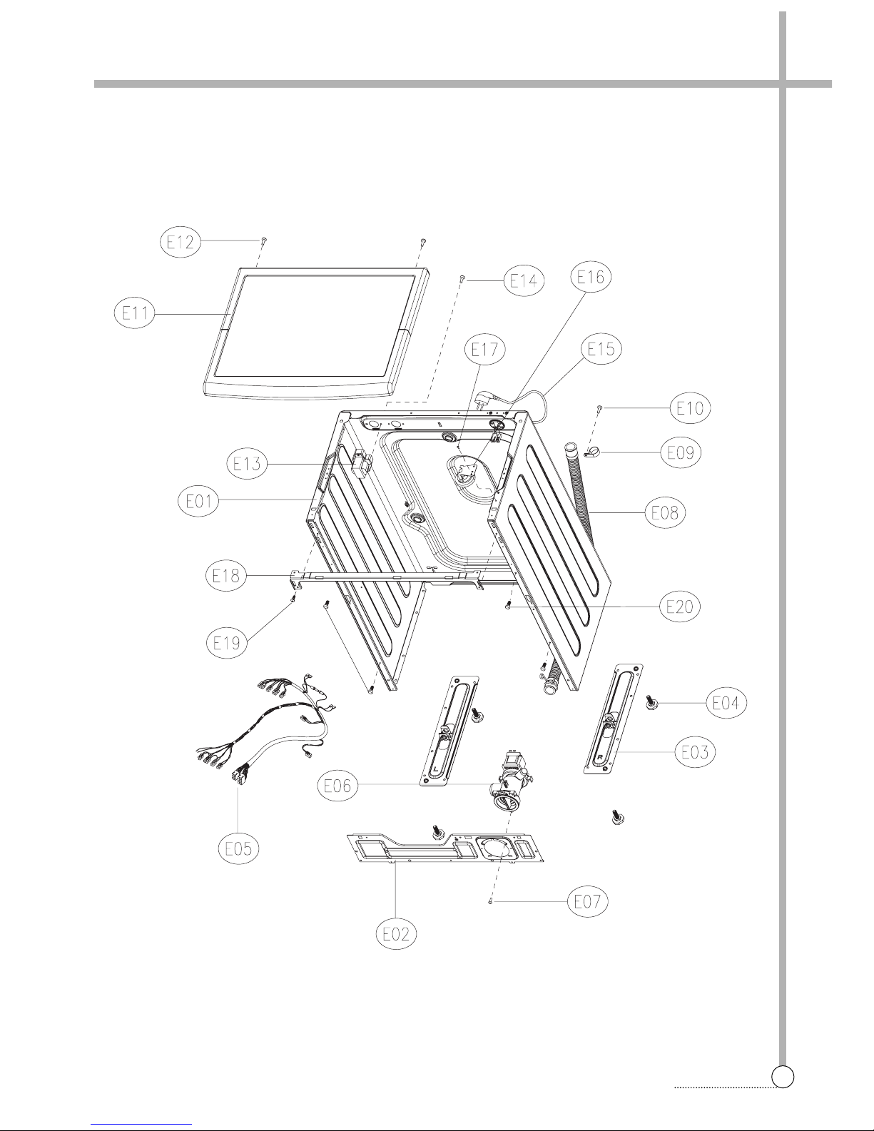
EXPLODE VIEW AND PARTS LIST
D01 TUB REAR AS 3618829900D-MU103 TUB REAR+BEARING HOUSING 1
D02 BEARING INNER 3616304700 6205ZZ SHENS 1
D03 BEARING OUTER 3616304800 6204ZZ SHENS 1
D04 WATER SEAL 361A600300 NBR 1
D05 GASKET TUB 3612324100 PI=4.5, L=1650, EPDM 1
D06 FIXTURE HEATER 3612009400 SUS, PI=2 1
D07 TUB FRONT 3618829600 FRPP 1
D08 GASKET 3612323500 EPDM 1
D09 CLAMP GASKET AS 3611204500 HSW3 1
D10 DRUM SUB AS 3617010400 SUS T=0.4 1
D11 SPIDER AS 361A301000 SPIDER(ALDC-8) + SHAFT(SM45C) 1
D12 SPECIAL BOLT 3616063000 STS430 M6*21 SI-LOCK 3
D13 LIFTER WASH 361A401100 PP NON-NANO
361A401110 D-MU80 NANO
NANO(OPTION)
D14 SPECIAL SCREW(TUB) 3616062700 SWRCH18A 5.6*30 12
D15 PULLEY 3618433201 ALDC12 SERRATION D-MU'S 1
D16 SPECIAL BOLT AS 3616063110 M8X27 S/W P/W SI-LOCK HEX:13 1
D17
UNIT MOTOR UNIVERSAL
36189L5H10
G&J MU10 NEW-CORE 220V 2POLES 38T CL.B
1
D18
SPECIAL SCREW(MOTOR)
3616062800 SWRCH18A 7.4*25.5 2
D19 BELT V 3616591300 GATES 3PJ1134 BUTADIENE RUBBER 1
D20 HEATER WASH 3612802460
VDE 230V 1.8KW ILCA & HEADWAY(TERMINAL)
1D-MU1031
D21 THERMISTOR WASH 361AAAAB10 R25=1.704KΩ, R80=11.981KΩ1
D22 HARNESS EARTH 3612794450 UL AWG18 L180 D-MU80 EARTH HEATER 1
D23 BALANCER WEIGHT L 3616109600 PP, INSERT 6.5KG 1 D-MU1031
D24 BALANCER WEIGHT R 3616109500 PP, INSERT 5KG 1 D-MU1031
D25 BALANCER WEIGHT T 3616109400 PP, INSERT 6.5K 1 D-MU1031
D26
SPECIAL SCREW(BALANCER)
3616062900 SWRCH18A 8*31 PW 6
D27 HOSE INLET 3613271600 EPDM 1
D28 CLAMP HOSE I 3611201400 HSW3, D=2.6, MFZN D=38 1
D29 SPRING SUSPENSION 3615116100 K=0.39, L=125 2
D30 FRAME *T 3612208500 SGCC T1.2 1
D31 HOSE DRAIN AS 3613272300 HOSE DRAIN(EPDM) + AIR TRAP(PP) 1
+ HOSE AIR(ID=4.0, OD=8, L=560, EPDM)
+ CLAMP AS(ID=81, CIMA)
+ CLAMP HOSE(D=26) + CLAMP HOSE I(D=38)
D32 SCREW TAPPING 7122401411 T2S TRS 4X14 MFZN 1
D33 DAMPER FRICTION 361A700140 70N CIMA ST=170-260 DL=202 2
361A700110 70N AKS OPTION
D34 DAMPER PIN 361A700200 AKS D=14.5 2
D35 UNIT BUBBLE PUMP AS 36189L4160 220-240V DBK-240DF RP CUSHION L=510 1 OPTION
D36
SPECIAL SCREW(BUBBLE)
3616007400 T2S TRS 4X10+24 2 OPTION
D37 EMI FILTER 3611908740 K27,MIN3.3MH, 0.22UF, 471(2EA) 1 OPTION
D38 SCREW TAPPING 7122401411 T2S TRS 4X14 MFZN 1
No. PART NAME PART CODE SPECIFICATION Q'TY REMARK
1
2