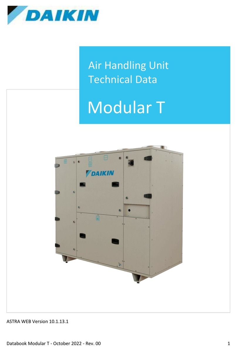
Daikin Skyline OAH003GDAC Manual
Other Daikin Air Handler manuals
Daikin
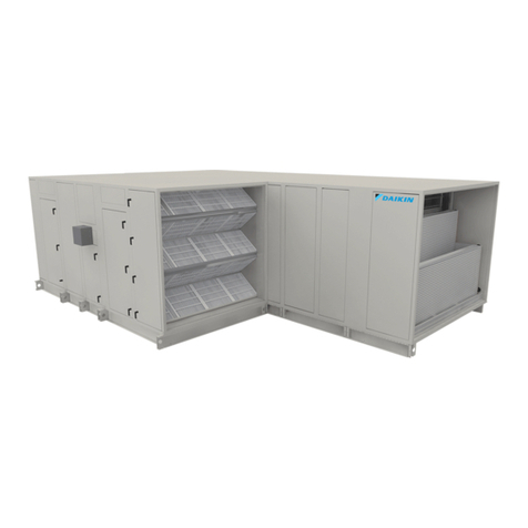
Daikin DCG Series User manual

Daikin
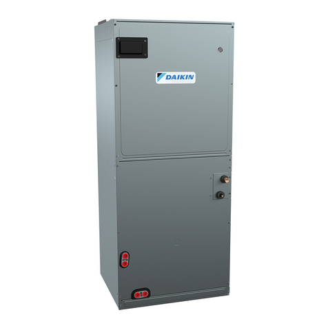
Daikin UATYQ30ABAY1 User manual
Daikin
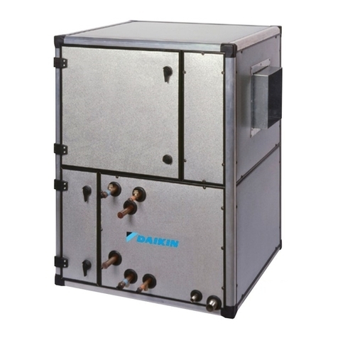
Daikin D-AHU Professional AH-ERQ-U User manual
Daikin
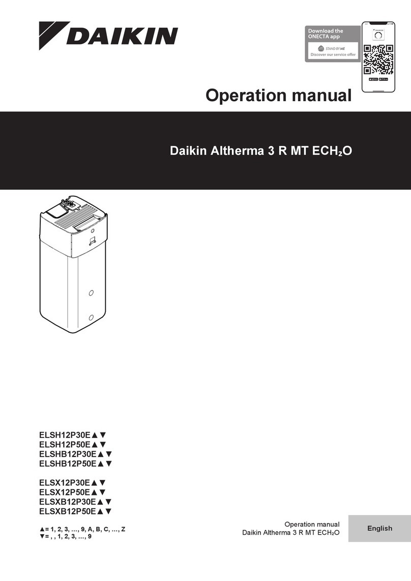
Daikin EEV Series User manual

Daikin
Daikin Vision CAC 003 C Manual
Daikin
Daikin LRYEQ16A7Y1 User manual
Daikin
Daikin Destiny VFD Series Manual

Daikin
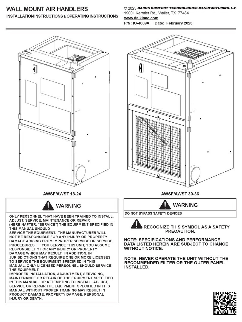
Daikin AWST18SU14 AA Series User manual
Daikin
Daikin Modular Rotary Service manual
Daikin
Daikin Skyline Manual
Daikin
Daikin Easdale 25 Manual
Daikin
Daikin RC35PRV16 User manual
Daikin
Daikin UATYA-B User manual
Daikin
Daikin Vision Manual
Daikin
Daikin DRC036 User manual
Daikin
Daikin Modular L Pro User manual
Daikin
Daikin ATM18MV2S User manual

Daikin
Daikin VISTA FXZQ TBVJU Dimension Guide
Daikin
Daikin FWF02D User manual
Daikin
Daikin RXQ12AHR User manual
Popular Air Handler manuals by other brands

Klimor
Klimor EVO-S Operation and maintenance manual

Salda
Salda SMARTY XP MOUNTING AND INSTALLATION INSTRUCTION

BLAUBERG
BLAUBERG KOMFORT Roto EC S400 user manual

Trenton
Trenton TPLP Series installation instructions

Kemper
Kemper CleanAirTower operating manual

Haier
Haier HB2400VA1M20 Installation & operation manual

Webasto
Webasto BlueCool A-Series operating instructions

RDZ
RDZ DA 701 Technical installation manual

Carrier
Carrier 39T Installation, Start-Up and Service Instructions

Armstrong Air
Armstrong Air BCE5V Series installation instructions

ActronAir
ActronAir CAY500T Installation and commissioning guide

Carrier
Carrier 40MBDAQ Service manual

Allied
Allied A93UH1E Service manual

Nortek
Nortek B6VMAI installation instructions

TemperZone
TemperZone Econex Pro OPA 1410RLTM4FPQD Installation & maintenance

RDZ
RDZ WHR 200 Technical installation manual

AAON
AAON H3 Series Installation operation & maintenance

Lennox
Lennox VEOA042N432U Installation & operation instructions

