Daikin VHF Manual
Other Daikin Heat Pump manuals
Daikin
Daikin REYQ-TA Series User manual

Daikin
Daikin DZ13SC User manual
Daikin
Daikin Altherma 3 H F How to use

Daikin
Daikin Altherma 3 H HT EPRA18DAW1 How to use

Daikin
Daikin EKHBX016BA User manual
Daikin
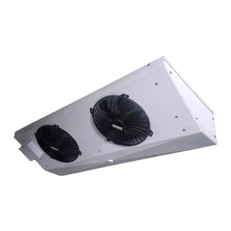
Daikin LFSLHS0200AXV1 Specification sheet
Daikin
Daikin EKCBX008BBV3 User manual

Daikin
Daikin EWYT CZ Series User manual
Daikin
Daikin IM 986-2 VHF Instruction Manual
Daikin
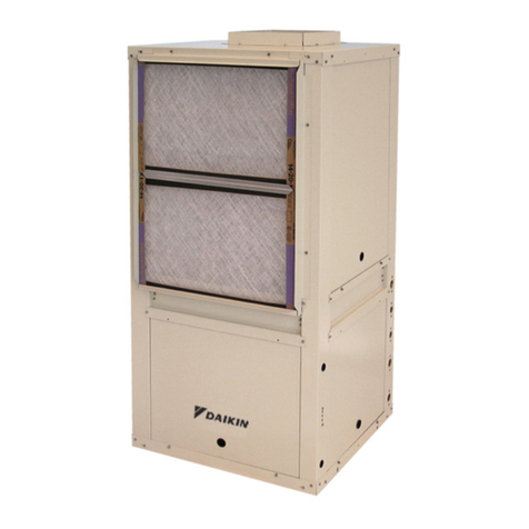
Daikin Enfinity VFC Manual
Daikin
Daikin Altherma EHYHBH05A Series How to use
Daikin
Daikin RXYQ96PYDN User manual

Daikin
Daikin FTX25JVEA9 User manual
Daikin
Daikin RYYQ14U7Y1B User guide
Daikin
Daikin CTXG25K2VMW User manual

Daikin
Daikin DZ18VC Series Operating instructions
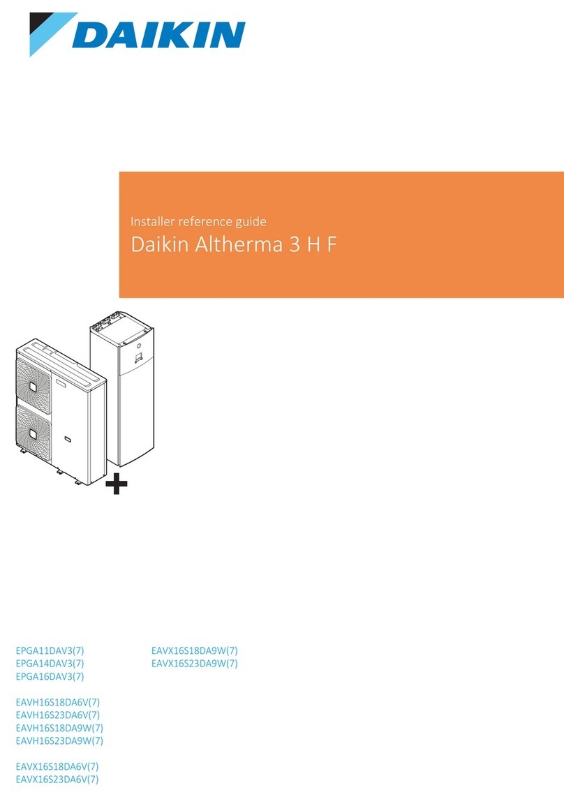
Daikin
Daikin Altherma EAVH16S23DA6V How to use

Daikin
Daikin VRV III RXYQ_PTJU Dimension Guide

Daikin
Daikin EHYHBH08AA Product information sheet

Daikin
Daikin Daikin Altherma 3 H F+W User manual
Popular Heat Pump manuals by other brands

MICROWELL
MICROWELL HP 1000 GREEN Installation and user manual

Sanyo
Sanyo SAP120FCH Service manual

Panasonic
Panasonic WH-SDF03E3E5 Design handbook

Bryant
Bryant 544B Specifications

Airxcel
Airxcel 45000 Series Installation, operation and maintenance instructions

Mitsubishi Electric
Mitsubishi Electric PUZ-SWM60VAA Service manual

Dimplex
Dimplex LI 16I-TUR Installation and operating instruction

Carrier
Carrier WSHP Open v3 Integration guide

TGM
TGM CTV14CN018A Technical manual

Carrier
Carrier 38MGQ Series installation instructions

Kokido
Kokido K2O K880BX/EU Owner's manual & installation guide

Viessmann
Viessmann VITOCAL 300-G PRO Type BW 2150 Installation and service instructions

Carrier
Carrier 48EZN installation instructions

Viessmann
Viessmann KWT Vitocal 350-G Pro Series Installation and service instructions for contractors

Ariston
Ariston NIMBUS user manual

Weishaupt
Weishaupt WWP L 7 Installation and operating instruction

GE
GE Zoneline AZ85H09EAC datasheet
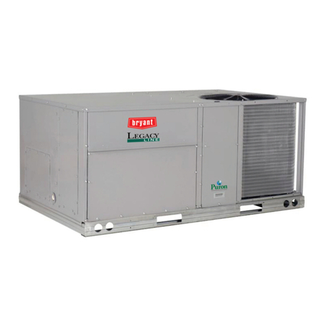
Bryant
Bryant Preferred Series installation instructions
