Quick reference
3BRC1E51
Remote controller
4PW52905-1
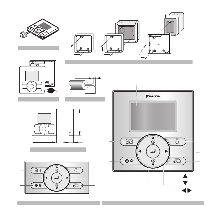
3. Remove the upper part of remote
controller (Refer to figure 1)
Insert a minus screwdriver into the slots (1) in the
lower part of the remote controller (2 places), and
remove the upper part of the remote controller.
4. Fasten the remote controller (Refer to
figure 2)
For the field supplied switch box, use optional accessory
KJB111A or KJB211A.
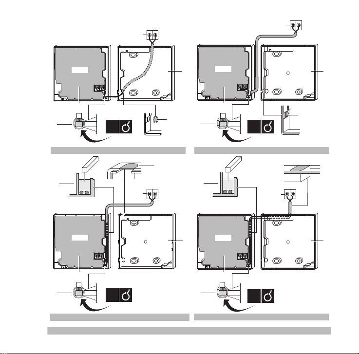
5. Wire the indoor unit (Refer to figure 8)
Wired from the rear (Refer to figure 8.1).
Wired from the left (Refer to figure 8.2).
Wired from the top (Refer to figure8.3).
Wired from the top center (Refer to figure 8.4).
Connect the terminals on the remote controller (P1,
P2), and the terminals of the indoor unit (P1, P2). (P1
and P2 do not have polarity.)
Wiring specifications
The PCB is mounted in the upper part of the
remote controller. Be careful not to damage
the board with the minus screwdriver.
1for exposed mounting, fasten with the two
included woodscrews (Ø3.5x32) and plugs.
2for flush-mounting, fasten with the two
included machine screws (M4x16).
NOTE Put on a flat surface. Be careful not to
distort the shape of the lower part of the
remote controller by overtightening the
mounting screws.
1indoor unit
2lower part of the remote controller
3upper part of the remote controller
4notch the part for the wiring to pass through
with nippers, etc.
5secure the wiring to the uppercase using
the wiring retainer and clamp.
NOTE When wiring, run the wiring away from
the power supply wiring in order to avoid
receiving electric noise (external noise).
Wiring type Size Max total
length
Sheathedvinyl
cord or cable 0.75–1.25 mm2500 m
NOTE 1. Peel the sheat for the part that has to
pass through the inside of the remote
controller case (L). Refer to figure 4
and the table below. It is important to
keep double isolation up through the
notch of the remote controller case.
2. For easy wiring, it’s better to keep ca.
10 mm difference between the length
of the two wires.
Wiring outlet
L
Top outlet Ca. 150 mm
Top center outlet Ca. 200 mm