DAINCUBE DTP10-D Instructions for use

Display type teach pendant
DTP10-D
Hardware user’s manual
(R1) Version
DAINCUBE Corp.
Full screen type
FORM 170705F –2018.09.10
DTP10-D Hardware user’s manual
Form 170710F-180910—Oct, 2018
DAINCUBE Corp.
Web: www.daincube.com
E-mail: support@daincube.com
Tel: 82-32-329-9783~4
Fax: 82-32-329-9785
#401-701, Bucheon TechnoPark 4-Danji,
655 Pyeongcheon-ro, Wonmi-gu, Bucheon-Si,
Gyeonggi-Do, Republic of Korea
Copyright © 2005–2018 Daincube
All rights reserved.
Printed in the Republic of Korea

Preface
Copyright notice
Copyright © 2005–2018 Daincube. All rights reserved.
Copying of this document, and giving it to others and the use or communication of the Contents thereof, is
forbidden without express authority. Offenders are liable to the payment of damages.
All rights are reserved in the event of the grant of a patent or the registration of a utility model or design.
Important information
This documentation is intended for qualified audience only. The product described herein is not an end user
product. It was developed and manufactured for further processing by trained personnel.
Disclaimer
Although this document has been generated with the utmost care no warranty or liability for correctness or
suitability for any particular purpose is implied. The information in this document is provided “as is” and is
subject to change without notice.
Trademarks
All used product names, logos or trademarks are property of their respective owners.
Product support
DAINCUBE Corp.
Web: www.daincube.com
E - MAIL: support@daincube.com
Safety precautions
Be sure to observe all of the following safety precautions.
Strict observance of these warning and caution indications are a MUST for preventing accidents, which
could result in bodily injury and substantial property damage. Make sure you fully understand all definitions
of these terms and related symbols given below, before you proceed to the manual.
Symbols
The following symbols may be used in this specification:
⚠Warning
Warnings indicate conditions that, if not observed, can cause personal injury.
⚠Caution
Cautions warn the user about how to prevent damage to hardware or loss of data.
✏Note
Notes call attention to important information that should be observed.

Revision history
Revision
Data
Comment
Version 0.1
2017.09.05
Initial Version
Version 1.0
2018.07.01
New Version
Version 1.1
2018.11.23
Change option
Version 1.2
2019.01.21
Added VGA connection method
Version 1.3
2019.04.01
Add Emergency Stop Switch table, Change Mode Select Switch
table
Version 1.4
2019.05.16
Junction Box Dimension Information Change

Contents
1. Introduction ...................................................................................................................6
1.1. General precautions................................................................................................................6
2. Safety information.........................................................................................................6
3. Warranty and warranty coverage.................................................................................7
3.1. Warranty period ......................................................................................................................7
3.2. Scope of the warranty.............................................................................................................7
3.3. Service coverage ....................................................................................................................7
4. Description.....................................................................................................................8
4.1. Front view...............................................................................................................................8
4.2. Tot view and dimension ..........................................................................................................8
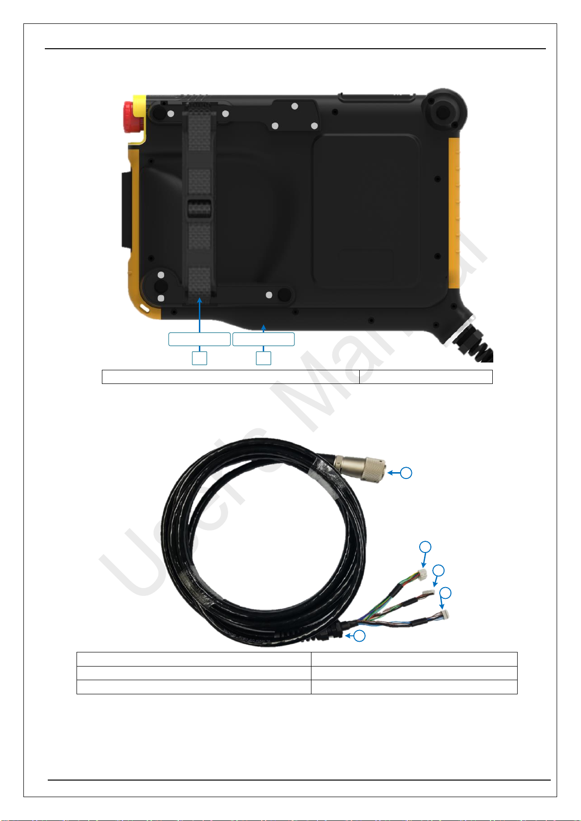
4.3. Rear view and dimension........................................................................................................9
4.4. System cable ..........................................................................................................................9
5. Features .......................................................................................................................10
5.1. Specification..........................................................................................................................10
5.2. Display & Touch screen........................................................................................................11
5.3. Safety switch.........................................................................................................................11
5.4. User interface........................................................................................................................11
5.5. Communication.....................................................................................................................11
6. Functions.....................................................................................................................12
6.1. Operation keys and functions................................................................................................12
6.2. System cable connection diagram.........................................................................................17
7. Junction box................................................................................................................21
7.1. Junction box..........................................................................................................................21
7.1.1. Junction box pin configuration .........................................................................................................22
7.1.2. Junction box Mechanical Information ..............................................................................................23
7.1.3. Junction Box Installation Instructions...............................................................................................23
8. Accessories .................................................................................................................24
8.1. Wall Bracket..........................................................................................................................24
8.2. Touch PEN ...........................................................................................................................25
9. Installation guide.........................................................................................................26
9.1. Power connection .................................................................................................................26
9.2. VGA connect.........................................................................................................................27
9.3. USB Cable (Touch, Key) connection......................................................................................27
9.4. Wiring....................................................................................................................................28
9.4.1. Emergency stop switch wiring .........................................................................................................28
9.4.2. Enabling switch wiring......................................................................................................................28
9.4.3. Select switch wiring..........................................................................................................................28
9.4.4. Power ...............................................................................................................................................29
9.4.5. Method wiring...................................................................................................................................29
9.4.6. Earthing............................................................................................................................................30
10. Package........................................................................................................................31
10.1. Packing list ........................................................................................................................31
10.2. Packing & label..................................................................................................................33
10.2.1. Label.............................................................................................................................................33
10.2.2. Packing product: 1Box = 1Product x 4ea.....................................................................................33

11. General care and maintenance ..................................................................................34
11.1. Cleaning ............................................................................................................................34
12. EC directives and standards......................................................................................34
12.1. EC directives......................................................................................................................34
12.2. Standards..........................................................................................................................34
13. Reference list...............................................................................................................35

DTP10-D hardware user’s manual
DAINCUBE Corp. 6 / 35
1. Introduction
Thank you very much for purchasing our product.
Improper usage or mishandling may result in a product not only being unable to deliver full functions but also
produce unexpected troubles or shorten the product’s life.
Please read this manual carefully, and operate the product properly by paying attention to its handling. When
operating the product, always keep this manual at hand and read the relevant items as required.
1.1. General precautions
Be sure to read this Instruction Manual for proper use of this product.
Part or all of this Instruction Manual may not be used or reproduced without permission.
Please take note that we shall not be liable for any effects resulting from using this Instruction manual.
This manual may be modified when necessary because of improvement of the product, modification or
changes in specifications.
Some drawings in this manual are shown as a typical example and may differ from the shipped product.
2. Safety information
Before unpacking and installing the product or adding devices on it, carefully read all the manuals that
came with the package.
Avoid using product in extreme dust, humidity and temperature conditions. Do not place the product in
wet area.
Before carrying out assembly and adjustment work or maintenance and inspection work of the machine,
be sure to disconnect the power cord. Otherwise, electric shock may result.
After turning OFF power, wait at least five minutes before servicing the product. Otherwise, residual
electric charges may result in electric shock.
⚠Warning
Be sure to check grounding before you use the unit. Danger of personal injury due to electric shock!
Be sure to use the unit within the voltage range indicated.
The operator must have a sufficient educational level and must know details of intended use described
in the user’s manual.
Be sure to check the wiring to the main unit.
When the user (customer) extends wiring, malfunction may occur due to faulty wiring. In this case,
inspect wiring thoroughly and check it for properness before turning on the power.
Before operating the unit, be sure to check that there is no danger in or around the operating range.
Do not allow water or oil to get on the unit and the power cord.
Install the unit in a place which can endure its weight and conditions while running.
Take care not to squeeze and thus damage the cable with any object.
Do not lay the cable over sharp edges to avoid damaging the cable sheath.
Check the mounting screws regularly so that they are always firmly tightened.
Never touch terminals directly or internal parts of controller.
Do not disassemble or modify the product.
Before carrying out assembly and adjustment work or maintenance and inspection work of the machine,
be sure to disconnect the power cord.
Connect the power supply after completing the adjustment of all the cables and switches.
⚠Caution
After the shutdown window, turn off the power supply. Otherwise the components could be destroyed
or undefined signals could occur.
To prevent the equipment from falling to the ground.
Never lay the device onto unstable surfaces. It could fall to ground and thus be damaged.
It is recommended to use the unit in an environment where no electrical noise is present.
In noisy environments, use a filter fitted.

DTP10-D hardware user’s manual
DAINCUBE Corp. 7 / 35
Never lay the device close to heat sources or into direct sunlight.
Avoid exposing the device to mechanical vibrations, excessive dust, and humidity or to strong
magnetic fields.
Make sure that no foreign objects or liquids can penetrate into the device.
Wipe the power plug with a clean, dry cloth periodically to eliminate dust.
Always pay special attention to the robot’s movement in the Teaching Mode.
3. Warranty and warranty coverage
The Teaching pendant you purchased has been delivered upon completion of our strict shipping test.
3.1. Warranty period
The warranty period is as follows:
12 months after our shipment.
3.2. Scope of the warranty
Where a defective condition occurs during proper use conditions and obviously under the responsibility of
the manufacturer, within the term above, we shall repair the product without charge.
However, any items that apply to the following are excluded from the warranty coverage.
The warranty is not valid if the defect is due to accidental damage, mishandling, misuse, voltage
fluctuation, high/low voltage or natural disaster.
If the product is repaired or tried to repair from unauthorized personal/Repair Shop.
If the product serial number is tempered.
The product is defective due to wear of parts, which can be considered as consumable parts by the
nature. (such as a cable)
Defects resulting from changes over time such as natural color fading of paint.
Defects resulting from mishandling or improper use.
Defects resulting from an inadequacy or error in maintenance and inspection.
Defects resulting from the use of any part other than our genuine parts.
Defects resulting from a modification not approved by us or our dealers.
Only a delivered product shall be singly warranted, and no damage induced by the defect of the delivery
product can be warranted. For repair, transport the product to our factory.
3.3. Service coverage
The cost of a delivered product does not include expenses for program creation and engineer dispatching.
Therefore, the following are charged separately even within the warranty term:
Maintenance and inspection.
Technical guidance and technical training in the operating instructions.
Technical guidance and technical training on program-related matters such as program creation.

DTP10-D hardware user’s manual
DAINCUBE Corp. 8 / 35
4. Description
DTP10-D is a portable Teach Pendant which is used to manipulate robots and various equipment
(semiconductor and LCD equipment). With this product, users can extend and duplicate the image on the
main monitor. In addition, users can use every function of the monitor, the keyboard and the mouse with
ease. All functions of the monitor, the keyboard and the mouse can be used very conveniently.
4.1. Front view
1
6
7
24
3
5
1 : TFT-LCD with touch screen
2 : Select switch
2 : Motor ON, Error clear switch
4 : Emergency stop switch
5 : Enabling switch
6 : Dual color LED x 3
7 : Right Keypad
[Table 4-1] Front function
4.2. Tot view and dimension
12
119
10
9 - USB host
10 - Debug serial
11 - Reset switch
12 - USB device
[Figure 4-1] Bottom function

DTP10-D hardware user’s manual
DAINCUBE Corp. 9 / 35
4.3. Rear view and dimension
Hand Strap
1
Touch Pen
2
[Table 4-2] Rear function
4.4. System cable
1
2
3
4
5
1: Circular plug 26pin connector
2: Power and switch connector
3: VGA connector
4: USB communication connector
5: Anti-angle cable grand
[Table 4-3] System cable
4 : Hand Strap
9 : Touch PEN

DTP10-D hardware user’s manual
DAINCUBE Corp. 10 / 35
5. Features
DTP10-D is a portable Teach Pendant which is used to manipulate robots and various equipment
(semiconductor and LCD equipment). With this product, users can extend and duplicate the image on the
main monitor. In addition, users can use every function of the monitor, the keyboard and the mouse with
ease. All functions of the monitor, the keyboard and the mouse can be used very conveniently.
Benefits of DTP10-D products :
The GUI can be sent (transmitted) from the Controller PC to LCD through VGA.
Unlike other companies (P** and M**companies) which use existing graphic panels to develop additional
UI, DTP10 simply extends and clones the screen of PC-type controllers.
It provides clear screen with no noises when transforming and transferring VGA signal.
We provided junction box which convenient wiring.
Various high resolution and clear screen
OSD function (brightness, contrast, color temperature, H-position, V-position, OSD timer)
Waterproof / dustproof (IP54)
1.5M drop (IEC standard 1.2M)
Certified: KC, CE, ISO 9001, ISO 14001
It weighs less than 1500g.
Cable length: 5m, 10m
26-pin circular type socket connector
Main function of built-in hardware :
Built-in alarm buzzer.
VGA transmission method : UTP transmission technology applied
Communication: USB HID(touch), Virtual COM Port (keypad, LED, buzzer)
Safety(Emergency, Enabling) switch: Use redundant switch
Operation and display panel :
TFT 10.1”1280x800, 16.7M Color with LED Backlight
4 wire resistive touch screen
Tact switch for soft key feeling and Membrane nameplate used
3 color LEDs for status display use
Desktop button settings
Wall bracket and desktop holder for installation
5.1. Specification
DTP10-D Hardware specification
Item
Contents
Remarks
LCD
TFT 10.1” 1280x800, 16.7M Color, LED backlight
Video interface
Standard VGA (Expandable, Replicable)
Supported
resolutions
1920 x 1080 60Hz (Not warranty)
1680 x 1200 60Hz (Not warranty)
1280 x 1024 60Hz (Not warranty)
1280 x 800 60Hz, 75Hz
1280 x 720 60Hz, 75Hz
1024 x 768 60Hz, 70Hz, 75Hz
800 x 600 60Hz, 72Hz, 75Hz
OSD function
Brightness, Contrast, Color temp, H-position, V-position, OSD timer
Communication
Virtual COM Port (keypad, LED, buzzer), USB HID (touch)
Touch
4-wire analog-resistive
LED
3 Color LED 3EA

DTP10-D hardware user’s manual
DAINCUBE Corp. 11 / 35
Keypad
Jog(+,-) 16EA, Function 2EA
Switch
Emergency stop / 3-Level enabling / Select / Motor on / Error clear
Power supply voltage
DC +24 ±5%
Power consumption
Max. DC 24V / 500mA
Environment
Operating temperature : 0℃to +45℃
Storage temperature : -20℃to +70℃
Humidity max 85% (Non-condensing)
Appearance
Size : 270 x 305 x 45mm / Weight : About. 1500g
(without cable)
Cooling method
Ambient
[Table 5-1] Hardware specification
5.2. Display & Touch screen
Items
Specification
Type
TFT LCD
Size
10.1”(216.96 X 135.60mm)
Resolution
1280 X 800 (Wide 8:5)
Representation
16.7M
Background lighting
42 LEDs (Light Emitting Diode)
Touch screen
4-Wire Analog-Resistive
[Table 5-2] LCD & Touch screen specification
✏Note :For smooth touch operation, we recommend removing a LCD protective film.
5.3. Safety switch
The Emergency stop switch, Select switch, and Enabling switch connect to the I/O of the system of the main
controller via the cable.
Emergency stop switch supports redundant configuration according to cable connection method.
Enabling switch was configured to confront the emergency situation by using a 3 step switch.
The Select switch is implemented so that the user can select three states.
5.4.User interface
In the user interface there is a touch screen, you can easily control the GUI environment of the platform
using the touch screen. The Keypad interface has direction key and three function keys on the left side and
twelve function keys on the right side. Also, 3 LEDs are mounted on the left / right, three LEDs each, and it
can be used according to the application.
5.5.Communication
DTP10-D provides USB Virtual COM Port and USB HID.
Control the keypad, LED, buzzer through serial of USB Virtual COM Port, and control touch through USB
HID.

DTP10-D hardware user’s manual
DAINCUBE Corp. 12 / 35
6. Functions
This chapter describes how to operate the teaching pendant.
6.1. Operation keys and functions
1
6
7
21280 X 800 TFT LCD & Touch
Safety Switch
Dry Contect Switch Enable Switch
Select Switch Emergency Switch
4
Motor ON, Error
clear Switch
35
3-color LED X 3
Keypad
[Figure 6.1] Pendant Controls and Function
(1) LCD Display
The 10.1” TFT LCD display area contains 1280 x 800pixels and can display up to 16.7M colors.
Shows programs and motion status for the UI.
(2) Touch panel
The resistive film method is used for the touch panel. By touching the button or data input area displayed on
the screen, it is an integrated type with LCD and touch panel together, you can select the menu and execute
the action.
(3) Right keypad (Axis Keys)
Each key and LED can define their respective function when developing by the user. For details, refer to the
software API document.
Generally, it is used as a shortcut for each axis of the robot.
In robot manual mode, these keys can be used to easily move and set each axis.
This key function is enabled by setting in the robot setting application.

DTP10-D hardware user’s manual
DAINCUBE Corp. 13 / 35
'a'
'e'
'c'
'g'
'i'
'k'
'b'
'f'
'd'
'h'
'j'
'l'
3-Color
LED *3
'n'
'o' 'p'
Function *2
[Figure 6.2] Right keys and LEDs
(4) Protective cover mounted
10. Debug Serial
12. USB host
11. Reset Switch8. Micro SD-Card
9. USB device
[Figure 6.4] A state that the protective cover is attached.
Interface ports should be used to open the protection cover.
8: Micro SD-Card - Unuse
9: USB Device - (Option) Unuse
10: Debug Serial - Unuse
11: Reset Switch - System Reset
12: USB Host - Mouse, Key board, USB memory stick

DTP10-D hardware user’s manual
DAINCUBE Corp. 14 / 35
[그림 6.3] 보호 커버 장착된 모습
(5) Emergency Stop Switch
NC1NC2
NC1NC2
EMTP1+
EMTP2+
EMTP2-
EMTP1-
External
Emergency Stop Switch
[Figure 6.5] Emergency stop switch
The emergency stop switch (large red handle on the upper right of the pendant) is a safety function that
stops the robot immediately and interrupts the power supply of the robot.
Position
Picture
Symbol
EMTP 1 (+,-)
EMTP 2(+,-)
Not
pressed
Short
Short
Pressed
Open
Open
[Table 6-1] Emergency Stop Switch function table

DTP10-D hardware user’s manual
DAINCUBE Corp. 15 / 35
(1) Enabling switch
This product is equipped with 3 stage Enabling switch as standard. As shown in the above drawing, the
enabling switch is on the back of the pendant. This switch is called the alias dead-man switch.
0 1 0
C1 NO1NC1
NC2C2 NO2
SWEN1+
SWEN1-
SWEN2-
SWEN2+
External
Enabling Switch
[Figure 6.6] Enabling switch
Action
Position
Picture
Symbol
Not pressed
Null
SWEN2-
SWEN2+
SWEN1-
SWEN1+
Pressed
Enabling
SWEN2-
SWEN2+
SWEN1-
SWEN1+
Pressed strong
Panic
SWEN2-
SWEN2+
SWEN1-
SWEN1+
[Table 6-2] Enabling switch operation

DTP10-D hardware user’s manual
DAINCUBE Corp. 16 / 35
(2) Mode select switch
This switch can be set in automatic or manual mode respectively.
NC2NC1
NO1NO2
C1 C2
SELCOM2+
SELCOM1+
SELCOM2-
SELCOM1-
ExternalSelect Switch
[Figure 6.7] Select switch
location
Drawing
Symbol
SELCOM 1 (+,-)
SELCOM 2(+,-)
Left
Short
Open
Center
Short
Short
Right
Open
Short
[Table 6-3] Select switch operation

DTP10-D hardware user’s manual
DAINCUBE Corp. 17 / 35
6.2. System cable connection diagram
System cables are customer custom made specifications. Cable length and type, connector type can be
changed to customer's specifications.
24pin Urethane cable
24AWG
24AWG
11
17
9
3
10
4
7
1
8
2
5
10
23
A
B
EMTP1+
EMTP1-
EMTP2+
EMTP2-
SWEN1+
SWEN1-
SWEN2+
SWEN2-
SELCOM1+
SELCOM2+
SELCOM1-
SELCOM2-
GND
GND
Blue+
DC 24V
Red Strip
Red
Orange
Orange Strip
Yellow
Yellow Strip
Green
Green Strip
Brown
Brown Strip
Black
Black Strip
Blue Sky
16
22
21
15
RED+
RED-
Green+
Green-
14
20
13
Video_GND
Blue-
TXD RS232
(Key)
VGA
System cable
Cable configuration
26pin Circular plug
(DTP-CU-26P)
AShield
White
Blue Sky Strip
12 RXD
White strip
19 TXD
Gray
18 RXD
Gray strip
B Shield
pink Strip
Purple
PurpleStrip
Blue
Blue Strip
pink
24
24AW
G
Urethane
jacket
jacket
10.5mm
Aluminu
m mylar
20AWG
Power
Cable
Aluminum
mylar
LAN
Cabl
e
Giga bit
Cable
BC
Pair
26AWG
A
Pair
26AWG
[Figure 6.8] Also connect system cables

DTP10-D hardware user’s manual
DAINCUBE Corp. 18 / 35
(1) Cable configuration
24AWG
Urethane
jacket
jacket
10.5mm
Aluminum
mylar
20AWG
Power
Cable
Pair
26AWG
Aluminum
mylar
LAN
Cable
Giga bit
Cable
S2 S3
Pair
26AWG
S1
[Figure 6.9] Cable configuration
(2) 26pin circular plug pin configuration
Plug Pin
Name
Description
Cable Color
System I/O
3
EMTP1+
Emergency switch the first signal (+)
RED
4
EMTP1-
Emergency switch the first signal (-)
Red Strip
5
EMTP2+
Emergency switch the second signal (+)
Orange
6
EMTP2-
Emergency switch the second signal (-)
Orange Strip
7
SWEN1+
Enabling switch the first signal (+)
Yellow
8
SWEN1-
Enabling switch the first signal (-)
Yellow Strip
1
SWEN2+
Enabling switch second signal (+)
Green
2
SWEN2-
Enabling switch second signal (-)
Green Strip
9
SELCOM1+
Select switch first signal (+)
Brown
10
SELCOM1-
Select switch first signal (-)
Brown Strip
11
SELCOM2+
Select switch second signal (+)
Black
17
SELCOM2-
Select switch second signal (-)
Black Strip
Display (VGA)
16
RED+
VGA Red+
Pink
22
RED-
VGA Red-
Pink Strip
21
Green+
VGA Green+
Purple
15
Green-
VGA Green-
Purple strip
20
BLUE+
VGA Blue+
Blue
14
BLUE-
VGA Blue-
Blue Strip
24
GND
VGA Ground
S2 Shield
Virtual Com Port (Touch&KEY)
12
USB_LINE_M0
USB0-
White Strip
13
USB_LINE_P0
USB0+
White
23
GND
USB GND
S1 Shield
18
USB_LINE_M1
USB1-
Gray Strip
19
USB_LINE_P1
USB1+
Gray

DTP10-D hardware user’s manual
DAINCUBE Corp. 19 / 35
Power
A
VCC
Input power DC 24V±5%
Blue Sky
B
GND
Ground
Blue Sky Strip
Shield
Shield
Shield
S3 Shield
[Table 6-4] Pin configuration of circular plug connector
(3) Cable specifications
[Table 6-5] Cable specifications
Item
Unit
specifications
AWG 26#×3 pair
Construction
NO. / mm
7 / 0.16TA
Wire Thickness
A-472
0.79¢
Color
(Blue×Blue Strip+Purple×Purple Strip+Pink×Pink
Strip)
Braided Shield
mm
7/0.10×16
AWG 26#×2 pair
Construction
NO. / mm
7 / 0.16TA
Wire Thickness
A-472
0.79¢
Color
(Gray×Gray Strip+White×White Strip)
Braided Shield
mm
7/0.10×16
AWG 24#×12C
Construction
NO. / mm
7 / 0.16TA
Wire Thickness
A-472
0.79¢
Color
(Blue×Blue Strip+Purple×Purple Strip)
(Gray×Gray Strip+White×White Strip)
AWG 20#×2C
Construction
NO. / mm
11 / 0.16
Wire Thickness
A-472
1.15¢
색상(Color)
(Blue×Blue Strip)
Tapping the whole
(26#×3Pr)+(26#×2Pr)+(24#×12C)+(20#×2C)
Thickness
Nom. Thick
mm
Jacket
Urethane
10~10.3¢⇓

DTP10-D hardware user’s manual
DAINCUBE Corp. 20 / 35
(4) Circular plug connector
Part Number
A
ØB
ØC
ØD
SRC6A21-26P
98.0
31.0
20.4
12.2
[Figure 6.10] Circular plug connector information
(5) Circular connector
Part Number
A
ØB
C(C')
D
E
F
G
SRC2A21-26S
25.6
23.6
27.7(25.5)
14
2.3
32
26
[Figure 6.11] Circular receptacle connector information
Table of contents
Other DAINCUBE Monitor manuals