Daktronics SPORTSOUND 2000HD Instruction Manual

Tables 1
Sportsound®2000HD
Audio System
Installation & Maintenance Manual
DD1798478 Rev 4 –12 March 2014
201 Daktronics Drive PO Box 5128 Brookings, SD 57006-5128
Tel: 1-800-DAKTRONICS (1-800-325-8766) Fax: 605-697-4746
Web: www.daktronics.com/support


DD1798478
P1340
Rev 4 –12 March 2014
DAKTRONICS, INC.
Copyright 2010-2014
All rights reserved. While every precaution has been taken in the preparation of this manual, the publisher
assumes no responsibility for errors or omissions. No part of this book covered by the copyrights hereon may be
reproduced or copied in any form or by any means—graphic, electronic, or mechanical, including photocopying,
taping, or information storage and retrieval systems—without written permission of the publisher.
Sportsound®is a registered trademark of Daktronics, Inc. All other trademarks used in this manual are property of their
respective owners.


Table of Contents i
Table of Contents
Section 1: Introduction ................................................................................................................. 1
1.1 Resources..................................................................................................................................1
1.2 Daktronics Nomenclature......................................................................................................2
1.3 Product Safety Approval .......................................................................................................2
Section 2: Sound System Components ........................................................................................ 3
2.1 Equipment Overview .............................................................................................................3
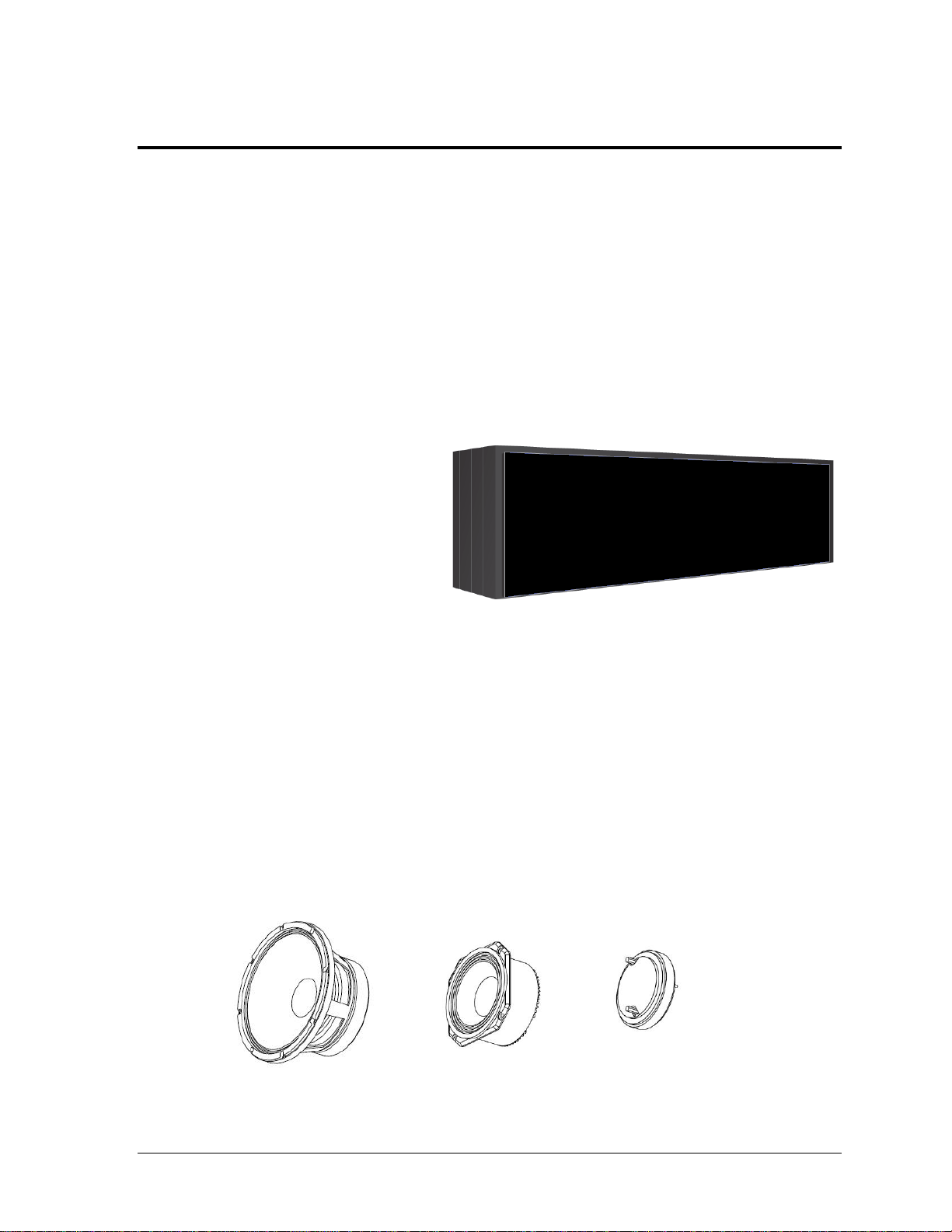
2.2 Sound Cabinet .........................................................................................................................3
Grille ..................................................................................................................................3
Drivers...............................................................................................................................3
Amplifier Components ...................................................................................................4
2.3 Fiber Conversion Box .............................................................................................................4
2.4 Source Equipment...................................................................................................................4
2.5 Signal Cables............................................................................................................................4
Section 3: Mechanical Installation............................................................................................... 5
3.1 Cabinet Installation.................................................................................................................5
Lifting the Cabinet ...........................................................................................................5
Mounting the Cabinet .....................................................................................................6
Aiming the Speakers .......................................................................................................6
Section 4: Electrical Installation................................................................................................... 7
4.1 Power/Signal Connections....................................................................................................7
Power.................................................................................................................................8
Signal .................................................................................................................................9
Grounding.........................................................................................................................9
4.2 Lightning Protection...............................................................................................................9
4.3 Fiber Conversion Box Connections ......................................................................................9
Section 5: Maintenance & Troubleshooting.............................................................................. 11
5.1 Maintenance...........................................................................................................................11
Grille Maintenance and Cleaning ................................................................................11
Replacing the Grille Mesh ............................................................................................11
5.2 Troubleshooting ....................................................................................................................14
Indicator Lights ..............................................................................................................15
Announcer’s Rack...................................................................................................15
Fiber Conversion Box .............................................................................................15
Section 6: Replacement Parts ..................................................................................................... 17
6.1 Sound Cabinet .......................................................................................................................17
6.2 Fiber Conversion Box ...........................................................................................................17
Section 7: Daktronics Exchange and Repair & Return Programs ............................................. 19
7.1 Exchange Program ................................................................................................................19
Before Contacting Daktronics ......................................................................................19

ii Table of Contents
7.2 Repair & Return Program ....................................................................................................20
Shipping Address ..........................................................................................................20
7.3 Daktronics Warranty and Limitation of Liability .............................................................20
Appendix A: Reference Drawings...................................................................................................21
Appendix B: Supplementary Manuals ...........................................................................................23
Appendix C: Daktronics Warranty and Limitation of Liability.....................................................25

Introduction 1
Section 1: Introduction
This manual explains the installation, maintenance, and troubleshooting of the Sportsound®2000HD
Sound Cabinet. For additional information regarding the safety, installation, operation, or service of
this system, refer to the telephone numbers listed in Section 7.
IMPORTANT SAFEGUARDS:
Please read and understand all instructions before beginning the installation process.
Do not drop control equipment or allow it to get wet.
Do not disassemble control equipment or electronic controls of the system; failure to
follow this safeguard will make the warranty null and void.
Disconnect system power when not in use or when servicing.
Disconnect system power before servicing power supplies to avoid electrical shock.
Power supplies run on high voltage and may cause physical injury if touched while
powered. Several disconnect switches may be required to de-energize the equipment.
Do not modify the cabinet structure or attach any panels or coverings without the
express written consent of Daktronics, Inc.
This manual is not specific to a particular installation. Project-specific information takes
precedence over any other general information found in this manual.
1.1 Resources
Figure 1 illustrates a Daktronics
drawing label. The drawing number
is located in the lower-right corner of
a drawing. This manual refers to
drawings by listing the last set of
digits and the letter preceding them.
In the example, the drawing would
be referred to as Drawing C-984140.
Throughout the manual, drawings are referenced as follows:
Reference Drawing:
System Riser; 2000HD ..........................................................................Drawing C-984140
Reference drawings in this manual are inserted in numeric order in Appendix A.
Daktronics identifies manuals by the DD or ED number located on the cover page of each
manual. For example, this manual would be referred to as DD1798478.
Figure 1: Daktronics Drawing Label

2 Introduction
1.2 Daktronics Nomenclature
Most components within this system carry a white label that lists the part number of the unit.
If a component is not found in the Replacement Parts List in Section 6, use the label to order
a replacement. Figure 2 illustrates a typical label. The part number is in bold.
Main Component Labels
Part Type
Part Number
Individual circuit board
0P-XXXX-XXXX
Assembly; a collection of circuit boards
0A-XXXX-XXXX
Wire or cable
W-XXXX
Fuse
F-XXXX
Transformer
T-XXXX
Metal part
M-XXX
Fabricated metal assembly
0S-XXXXXX
Specially ordered part
PR-XXXXX-X
Accessory Labels
Component
Label
Termination block for power
or signal cable
TBXX
Grounding point
EXX
Power or signal jack
JXX
Power or signal plug for the
opposite jack
PXX
Following the Replacement Parts List is the Daktronics Exchange Policy and the Repair &
Return Program. Refer to these instructions if replacing or repairing any system component.
1.3 Product Safety Approval
Daktronics outdoor displays are ETL listed and tested to CSA standard for outdoor use.
Contact Daktronics with any questions regarding testing procedures.
Figure 2: Typical Label

Sound System Components 3
Section 2: Sound System Components
2.1 Equipment Overview
The Sportsound 2000HD audio system consists of the following elements:
Sound Cabinet
Fiber Conversion Box
Source Equipment
Signal Cables
Note: All products in this system are tested individually for product safety approval.
2.2 Sound Cabinet
The Sportsound 2000HD audio
system cabinet (Figure 3) is 6'-0"
(1829 mm) high, 22'-0" (6706 mm)
wide, and 3'-6" (1067 mm) deep.
It is composed of a steel skeleton
sheeted in custom aluminum
paneling with eight rear access
doors. The cabinet is powder coat
black with a wrinkle finish.
Grille
The grille of the cabinet consists of a woven flame resistant acoustical mesh. The mesh can be
printed in a variety of colors to display advertising, sponsors, or logo designs. The printable
area is 5'-4 3/4" (1645 mm) high by 21'-9" (6630 mm) wide.
Drivers
Three different types of drivers are used in the sound cabinet:
12" (305 mm) low frequency drivers: Daktronics part # A-2306: (Figure 4)
8" (203 mm) mid-range drivers: Daktronics part # A-2305 (Figure 5)
1.4" (36 mm) high frequency drivers: Daktronics part # A-2302 (Figure 6)
Figure 3: Sportsound 2000HD Cabinet with Grille
Figure 4: A-2306
Figure 5: A-2305
Figure 6: A-2302

4 Sound System Components
Amplifier Components
In sound systems, the amplifier is the last component before the drivers. It receives a signal
from the source equipment and amplifies it to power the speakers. The Sportsound 2000HD
sound system utilizes ten (10) power amplifiers with built-in Digital Signal Processor (DSP),
which manages equalization, limiting, compression, and crossover functions.
Note: The DSP program is set at the factory and is not user adjustable.
2.3 Fiber Conversion Box
The fiber conversion box (Figure 7) converts the
analog audio signal from the source equipment
into fiber optic signal that goes out to the control
enclosure. The box is typically permanently wall-
mounted near the source equipment location.
The fiber conversion box includes an analog
backup signal. This provides a redundant safety,
in case the fiber link to the sound cabinet is lost.
To go into analog backup mode, simply turn the
switch to the ANALOG position.
Refer to Section 4.3 for more information about
the fiber conversion box.
2.4 Source Equipment
The Sportsound 2000HD audio system is compatible with all Daktronics standard control
systems. Refer to the manual provided with the control system for proper operation.
2.5 Signal Cables
Cable specifications are as follows:
6-core, multimode 50-micron fiber optic cable from fiber conversion box to fiber
splice box or control enclosure (part # W-1489)
If included with a Daktronics scoreboard or display, the sound system may share
fiber optic cable (12-core part # W-1490).
1 pair, 22 AWG audio cable from fiber conversion box to control enclosure for analog
backup (part # W-1615)
50' (15.2 m) fiber patch cable from fiber splice box to control enclosure (part # W-1512)
Figure 7: Fiber Conversion Box

Mechanical Installation 5
Section 3: Mechanical Installation
A qualified technician must install the Sportsound 2000HD sound system cabinet. It is the customer’s
responsibility to ensure that a qualified structural engineer approves the mounting structure and any
additional hardware needed to secure the cabinet.
The cabinet must be installed no further than 100' (31 m) behind the goal post to provide coverage for
seating from goal to goal.
Note: Daktronics assumes no responsibility for the structure’s integrity. The engineer responsible
for the attached-to base structure shall evaluate the adequacy of their structure to support the
gravity loads imparted by the cabinet at each attachment point in combination with other
associated loading conditions. Daktronics assumes no responsibility for system damage or injury
resulting from installation methods that deviate from attachment details specified on shop
drawings. Daktronics also assumes no liability for system damage or injury resulting from
incorrect setup, or incorrect lifting methods preformed by non-Daktronics employees.
3.1 Cabinet Installation
Reference Drawings:
Shop Drawing; Sound System; 2000HD................................................Drawing C-330901
The Sportsound 2000HD sound system installation consists of lifting and mounting the
cabinet onto an existing support structure. Refer to Drawing C-330901 in Appendix A for
further mounting detail.
Lifting the Cabinet
The Sportsound 2000HD speaker cabinet is shipped
with four (4) 5/8" lift eyes (Figure 8) for lifting the
cabinet into place.
Note: Three (3) shipping brackets are installed to
the top of the cabinet for shipping purposes only.
Each bracket is attached to the cabinet with two (2)
1/2" hardware sets. Remove all shipping brackets
prior to lifting and installing the cabinet.
Daktronics strongly recommends using a spreader bar, or lifting bar, to lift the cabinet.
Spreader bars ensure the force on the eyebolts remains straight up, minimizing lifting stress.
Figure 9 illustrates the preferred lifting method on the left and an acceptable alternative
lifting method on the right. When lifting the cabinet:
Use a spreader bar if possible.
Use every lifting point provided.
Figure 8: Shipping Bracket & Lift Eyes

6 Mechanical Installation
Cables and chains attached to the eyebolts and directly to a center lifting point, as shown in
the right-hand example in Figure 9, can create a dangerous lateral force on the eyebolts and
may cause the eyebolts to fail. The smaller the angle between the cable and the top of the
cabinet, the lighter the sign must be to safely lift it. If this method must be used, ensure a
minimum angle between the chain and cabinet of at least 45°.
Do NOT attempt to lift the cabinet if the angle is less than
45 degrees. Exceeding load angles or weight limits could
cause the bolts in the cabinet to buckle, resulting in
serious damage to the equipment or injury to personnel.
Also, loads should be applied directly in the plane of the
eyebolt as shown in Figure 10.
Note: Daktronics assumes no liability for damages
resulting from incorrect setup or lifting methods.
Eyebolts are intended for lifting only. Do not attempt
to permanently support the cabinet with the eyebolts
or eyebolt holes.
If installers remove the eyebolts, use 5/8" bolts to plug
the holes.
Mounting the Cabinet
The sound cabinet will be mounted atop a frame that must be certified by a structural
engineer. To mount the system in place, position the cabinet on the structure where it is to be
mounted. Weld the cabinet’s bottom members to the structure at the locations indicated on
the shop drawing. Refer to Drawing C-330901 in Appendix A for mounting requirements.
Aiming the Speakers
Once the cabinet has been mounted in place, it may be necessary to adjust the direction of the
speakers based on the specific facility. Drawing C-1023805 in Appendix A provides speaker
aiming instructions as well as recommended angles to position the speakers, based on the
cabinet’s location in relation to the seating area(s).
Figure 9: Lifting Methods
Figure 10:Eyebolt Plane Load

Electrical Installation 7
Section 4: Electrical Installation
CAUTION –RISK OF ELECTRIC SHOCK: Only qualified individuals should perform power routing
and termination to the system. It is the responsibility of the electrical contractors to ensure that all
electrical work meets or exceeds local and national codes. Failure to follow installation guidelines will
result in audible noise on the sound system and possible damage to internal components.
Notes:
This product is not provided with mains disconnect. Customer shall provide disconnect at
base of sound system location that meets or exceeds local and national electrical codes.
Several disconnect switches may be required to de-energize the equipment before servicing.
The control enclosure, located in the sound cabinet, shall not be exposed to dripping or
splashing, and no objects filled with liquid shall be placed on the control enclosure.
4.1 Power/Signal Connections
Reference Drawings:
System Riser; 2000HD ..........................................................................Drawing C-984140
System Riser; Electrical & Audio Notes.................................................Drawing B-985713
Schematic; Control Enclosure/Sound Cabinet 2000HD ......................Drawing B-1082599
Drawing C-984140 details power and signal connections of the Sportsound 2000HD sound
system. To gain access to internal power and signal connection points, open the far right rear
access door (Figure 11). Turn all latches a 1/4 turn using a flathead screwdriver (older latches
can be turned with fingers). Tilt the top of the door away from the cabinet. With the door
tilted, use the handle to lift it up and out of the doorframe.
Figure 11:Sound Cabinet Access Doors, Rear View

8 Electrical Installation
To access the internal components of the control enclosure, first loosen the 6 screws with a
Philips head screwdriver, and then use the handle to lift the enclosure cover up and away so
the screws pass through the keyholes.
Refer to Figure 12 for component and connection locations within the sound cabinet and
control enclosure and Drawing B-1082599 in Appendix A for a detailed wiring schematic.
Power
The system requires three (3) 20 amp 208/230/240 circuits (50 or 60 Hz); 2W + GND per
circuit. Power wiring must be run in conduit up into the bottom of the sound cabinet and
terminated at TBL2. Refer to Detail “F” of Drawing C-984140.
Figure 12:Control Enclosure Components & Connections (Covers Removed)

Electrical Installation 9
Signal
Six-core, multimode 50-micron fiber optic cable (Daktronics part # W-1489) must be run in
conduit from the fiber conversion box location and terminated in a fiber splice box near the
sound cabinet. Fiber patch cables (part # W-1512) will then run in conduit to the control
enclosure media converter (FCC2). Refer to Detail “C”and Detail “E” of Drawing C-984140.
If there is no fiber splice box, the fiber is terminated directly to the media converter.
Note: The sound system may instead use 12-core (part # W-1490) fiber optic cable.
For the analog backup signal, 1 pair, 22 AWG cable (part # W-1615) must be run in conduit
from the fiber conversion box location to the sound cabinet control enclosure (TRX1). Refer to
Detail “E”of Drawing C-984140. The analog backup cable may pass through, but not
terminate in, a fiber splice box.
Grounding
The sound cabinet must be grounded according to the provisions outlined in Article 250 and
600 of the National Electrical Code and according to the specifications in this manual or the
warranty will be void. Proper grounding is necessary for reliable equipment operation and
protects the equipment from damaging destructive disturbances and lightning.
Daktronics recommends a resistance-to-ground of 10 ohms or less. The electrical contractor
performing the electrical installation can verify ground resistance. Daktronics Sales and
Service personnel can also provide this service. The sound system must be earth-ground.
The material for an earth-ground electrode differs from region to region and may vary
according to conditions present at the site. Consult local and national electrical codes.
Daktronics does not recommend using the support structure as an earth-ground electrode;
concrete, primer, corrosion, and other factors make the support structure a poor ground.
Note: The support structure may be used as an earth-ground electrode only if designed to
do so. A qualified inspector must approve the support structure and grounding methods.
4.2 Lightning Protection
The use of a disconnect near the system to completely cut all current-carrying lines
significantly protects the circuits against lightning damage. In order for this device to provide
protection, the power must be disconnected when the system is not in use.
4.3 Fiber Conversion Box Connections
Important Notes:
The fiber box shall not be exposed to dripping or splashing, and no objects filled with
liquid shall be placed on the fiber box.
The fiber box consists of Class 1 construction and shall be connected to a mains
socket outlet with a protective earth-ground connection.
The fiber box utilizes a power cord with wiring inlet as a means for disconnection
from power. This means of disconnection shall remain readily operable in all cases.

10 Electrical Installation
Refer to Figure 13 for
external fiber conversion box
connections and Figure 14
for internal connections and
component locations.
Refer to Detail “A”in
Drawing C-984140 for
analog backup connection
and Detail “B”for fiber
connection. Drawing A-
1095894 provides a detailed
wiring schematic.
Figure 13:External Fiber Conversion Box Connections
Figure 14:Internal Fiber Conversion Box Connections & Components (Cover Open)

Maintenance & Troubleshooting 11
Section 5: Maintenance & Troubleshooting
5.1 Maintenance
Grille Maintenance and Cleaning
To allow maximum acoustic transparency, the front of the cabinet contains a PVC mesh
grille. Do not apply anything to the surface that may obstruct the holes in the material.
To maintain the brightness of the colors and prolong the life of the grille, periodic cleaning is
necessary. Failure to clean periodically may result in permanent discoloration or staining.
When cleaning, use a mild soapy solution (Dove®, Ivory®, etc.) and a very soft brush, moving
in a circular motion. Rinse with clean water using normal faucet pressure.
Note: Do not use a power washer.
Replacing the Grille Mesh
If the speaker mesh fades or tears over time, or if new graphics/logos are desired, it may be
replaced. Only qualified sign companies should be used to replace the speaker mesh. Refer to
Drawing B-983337 for speaker mesh layout. Contact Daktronics for mesh reordering.
1. Removing Mesh Frame
The front of the sound cabinet has a removable aluminum frame that secures the
speaker mesh. This frame is attached to the sound cabinet with a total of twenty (20)
3/8" hardware sets, with ten (10) sets at both the top and bottom of the frame.
a. Carefully remove all mounting hardware and safely lower mesh frame to the
ground. Set the frame on a level surface large enough so that the weight is
supported by the aluminum frame and not on the mesh.
b. Loosen the set screws using a square driver on radius cover and remove.
2. Removing Tension Clips
Insert the tip of a standard
slotted screwdriver into the
recess located at the backside
of the tension clip (Figure 15).
Rotate or tilt the screwdriver to
separate the tension clip teeth
away from the frame. This will
allow the tension clip to be
removed from the frame by
prying or pulling it up and out.
Slide the mandrel out of the
tension clip to release the mesh.
Figure 15:Removing Tension Clips

12 Maintenance & Troubleshooting
3. Attaching New Speaker Mesh
When ordered through Daktronics, the mesh has a line with a series of tick marks
printed on the front (Figure 16). These tick marks are used to indicate the location of
the tension clips and mandrels.
a. Place a mandrel, smooth side up, centered on the tick mark.
b. Fold the mesh around the mandrel. Ensure the groove in the mandrel is
towards the inside of the mesh (Figure 17).
c. Snap a tension clip over the mandrel and mesh (Figure 18). Do not try to
drive both ends of the clip down onto the mandrel and fabric at the same
time; snap one end down and then the other.
d. Continue to place a mandrel and tension clip on every tick mark.
Figure 16:Tick Marks on Mesh
Figure 17:Folding Mesh
Figure 18:Attach Tension Clip

Maintenance & Troubleshooting 13
e. Lay the mesh across the frame and snap each clip into the tension channels
(Figure 19).
f. Use the tensioning tool provided with the mesh replacement kit (part # 0A-
1340-2032) to drive the tension clips into the tension channels (Figure 20).
Start with one or two clicks.
g. Work around the frame, tightening down all the tension clips until all the
wrinkles are removed and the mesh is properly taut.
Note: Do not over-tension! This may cause damage to mesh graphics. Apply
just enough tension to achieve a smooth, flat surface.
h. Place the radius covers on the end of the mesh frame and tighten the set
screws on the radius cover.
4. Reattach Mesh Frame
Safely lift mesh frame back in place on the front of the sound cabinet and attach with
the twenty (20) 3/8" hardware sets. Ensure the frame is snug tight against the cabinet.
Figure 19:Clips in Channels
Figure 20:How to Use Tensioning Tool
Note: Pull on the corners of the mesh
to remove any wrinkles. When
pulling on the fabric, do not pull
directly on the fabric flap or tension
clip, or the clip may pop off. When
pulling on the face, grasp the fold
and pull the face into place.

14 Maintenance & Troubleshooting
5.2 Troubleshooting
This section lists potential problems with the system, indicates possible causes, and suggests
corrective action. This list does not include every possible problem, but it does represent
some of the more common situations that may occur. If the problem persists, please contact
Daktronics for assistance.
Note: Be sure to power on the announcer’s rack, fiber conversion box, and cabinet breakers.
Make sure all connections from source to the fiber conversion box are complete.
Symptom/Condition
Possible Cause
Potential Solution
No power to cabinet
Breaker is off at sign
Bad A-2238 power supply
Turn breaker ON
Order new power supply
No audio from cabinet,
but source (announcer’s rack)
shows output
No power at cabinet
Fiber conversion box is
unplugged from wall outlet
or cable to announcer’s
rack
Turn breaker on
Plug in fiber conversion box
No audio from cabinet
Fiber link down/
TX-RX swap
Fiber link down/
broken fiber
Swap TX-RX fibers to fix
link
Replace fiber splice, repair
fiber termination/cable
Weak audio from cabinet
Improper gain at Analog to
Digital Converter (in fiber
conversion box)
Adjust gain according to
Biamp Audia Input &
Output Expanders
Operation Manual in
Appendix B
Poor sound quality from cabinet
(distortion)
Poor source material
(CD or MP3 with heavy
compression or distorted
material)
Clipping audio at source
(announcer’s rack) output
Blown driver in cabinet
Use high quality audio files
(.wav)
Bring source level down
below clip
Contact Daktronics to verify
defective equipment and
replace
Audio from cabinet is
intermittent
Amplifier modules within
speaker cabinet are over
driven into protect mode
Analog to Digital
Converter (in fiber
conversion box) is failing
Reduce source output level
Contact Daktronics to
replace Analog to Digital
Converter
Other manuals for SPORTSOUND 2000HD
1
Table of contents
Other Daktronics Stereo System manuals

Daktronics
Daktronics Sportsound SSR-200 User manual

Daktronics
Daktronics SPORTSOUND SSN-250 User manual

Daktronics
Daktronics SPORTSOUND 2000HD User manual

Daktronics
Daktronics SPORTSOUND 500HD User manual

Daktronics
Daktronics SPORTSOUND 1500HD GEN II User manual

Daktronics
Daktronics Sportsound SS-200 User manual

Daktronics
Daktronics Sportsound SSR-200 User manual

Daktronics
Daktronics Sportsound SSR-300 User manual