Daktronics SPORTSOUND SSN-250 User manual

201 Daktronics Drive
Brookings, SD 57006-5128
www.daktronics.com/support
800.325.8766
SPORTSOUND INDOOR SSN-250
AUDIO SYSTEM
INSTALLATION MANUAL
P1756
DD3580600
Rev 00
01 April 2019

Copyright © 2019
All rights reserved. While every precaution has been taken in the preparation of this manual, the publisher assumes no
responsibility for errors or omissions. No part of this book covered by the copyrights hereon may be reproduced or copied
in any form or by any means—graphic, electronic, or mechanical, including photocopying, taping, or information
storage and retrieval systems—without written permission of the publisher.
Daktronics trademarks are property of Daktronics, Inc. All other trademarks are property of their respective companies.

– i –
Table of Contents
1 Introduction���������������������������������������������������������������������������������������������������������������������������1
Important Safeguards ..........................................................................................................................1
Resources ..............................................................................................................................................1
Daktronics Nomenclature ...................................................................................................................2
2 Sound System Components ������������������������������������������������������������������������������������������������3
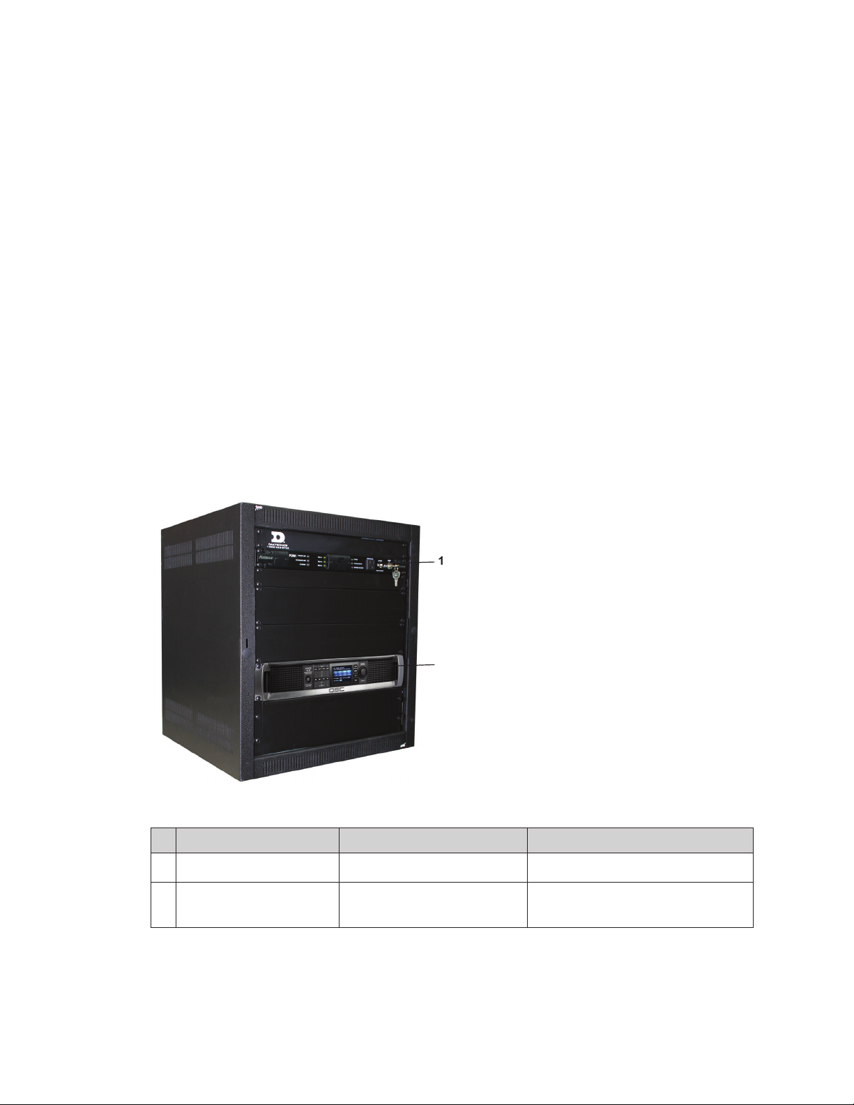
Equipment Overview ...........................................................................................................................3
Speaker Cluster.....................................................................................................................................3
Drivers ������������������������������������������������������������������������������������������������������������������������������������������������4
Control Enclosure..................................................................................................................................4
Amplier ��������������������������������������������������������������������������������������������������������������������������������������������5
Source Equipment................................................................................................................................5
Signal Cables ........................................................................................................................................5
3 Mechanical Installation �������������������������������������������������������������������������������������������������������6
Installation Location .............................................................................................................................6
Speaker Assembly ................................................................................................................................6
Speaker Mounting ................................................................................................................................6
Suspension Method��������������������������������������������������������������������������������������������������������������������������6
Rigid Attachment Method ���������������������������������������������������������������������������������������������������������������7
Aiming �����������������������������������������������������������������������������������������������������������������������������������������������7
Mounting the Control Enclosure .........................................................................................................7
4 Electrical Installation ������������������������������������������������������������������������������������������������������������8
Power/Signal Connections..................................................................................................................8
Signal IN ��������������������������������������������������������������������������������������������������������������������������������������������8
Power IN ��������������������������������������������������������������������������������������������������������������������������������������������9
Grounding.......................................................................................................................................9
Speaker Line OUT to Junction Box ��������������������������������������������������������������������������������������������������9
Speaker Line OUT to Cluster ����������������������������������������������������������������������������������������������������������10
Amplier Presets..................................................................................................................................10
5 Troubleshooting ������������������������������������������������������������������������������������������������������������������11
Sound Cabinet Troubleshooting .......................................................................................................11
Resistance Check ��������������������������������������������������������������������������������������������������������������������������11
Test Tones ����������������������������������������������������������������������������������������������������������������������������������������13
Equalization & Vertical Coverage ������������������������������������������������������������������������������������������������13
Amplier Indicators ������������������������������������������������������������������������������������������������������������������������13
6 Replacement Parts �������������������������������������������������������������������������������������������������������������14
Sound Cabinet Components............................................................................................................14
Control Components .........................................................................................................................14
7 Daktronics Exchange and Repair & Return Programs ����������������������������������������������������15
Exchange Program ............................................................................................................................15
Repair & Return Program...................................................................................................................16
Daktronics Warranty & Limitation of Liability ...................................................................................16

– ii –
Table of Contents
A Reference Drawings �����������������������������������������������������������������������������������������������������������17
B Supplementary Manuals����������������������������������������������������������������������������������������������������27
C Daktronics Warranty & Limitation of Liability��������������������������������������������������������������������29

Introduction
1
1 Introduction
This manual explains the installation, maintenance, and troubleshooting of a Sportsound®
SSN-250 Indoor Audio System with integrated audio control rack. For additional
information regarding safety, installation, operation, or service, refer to Section 7:
Daktronics Exchange and Repair & Return Programs (p�15). This manual is not specic
to a particular installation. Project-specic information takes precedence over any other
general information in this manual.
Important Safeguards
• Read and understand all instructions before beginning the installation process�
• Disconnect system power when not in use or when servicing�
• Do not modify the cabinet structure or attach any panels or coverings without the
express written consent of Daktronics�
• Do not disassemble control equipment or electronic controls of the system; failure to
follow this safeguard will make the warranty null and void�
• Do not drop the control equipment or allow it to get wet�
• Always turn off and/or unplug the control equipment when it is not in use� This keeps
equipment protected from power spikes and lightning�
• Never yank the power cord from the outlet� Grasp the plug and pull to disconnect�
• Do not let any power cord touch hot surfaces or hang over the edge of a table that
would damage or cut the cord� Arrange the cord with care so that it will not be
tripped over�
• Inspect equipment for shipping damage such as rattles and dents, and verify that
all equipment is included as itemized on the packing slip� Immediately report any
problems to Daktronics; save all packing materials if exchange is necessary�
Resources
Figure 1 illustrates a Daktronics drawing label.
This manual refers to drawings by listing the last
set of digits. In the example, the drawing would
be referred to as DWG-1007804. All references to
drawing numbers, appendices, gures, or other
manuals are presented in bold typeface. Any
drawings referenced in a particular section are
listed at the beginning of it as shown below:
Reference Drawing:
System Riser Diagram....................................................................................... DWG-1007804
Daktronics identies manuals by the DD or ED number located on the cover page.
Daktronics has a searchable knowledgebase of common questions and troubleshooting
tips: www.daktronics.com/support.
Visit the Daktronics Support YouTube channel to learn how
to properly operate Sportsound racks: www.youtube.com/
DaktronicsSupport.
Drawing Number
Figure 1: Drawing Label

Introduction
2
Project-specic information takes precedence over any other general information found
in this manual. Such information may include:
• Schematic Drawings: describe internal power and signal wiring
• Shop Drawings: describe mounting methods to structural elements, access method
(front or rear), and power and signal entrance points
• System Riser Diagrams: describe power and signal connections between system
components and the control location; may also include control room layout and
schematic
• Final Assembly Drawings: describe internal component locations and detailed
product appearance with part numbers and quantities
Ensure all applicable material has been gathered before beginning the installation.
Contact a Daktronics sales coordinator or project manager.
Daktronics Nomenclature
Most components have a white label that lists the part number
(Figure 2). Part numbers will also appear on certain drawings. If a
component is not found in Section 6: Replacement Parts (p�14),
use the label to order a replacement. Refer to Section 7: Daktronics
Exchange and Repair & Return Programs (p�15) if replacing or
repairing any component.
Main Component Labels
Part Type Part Number
Individual circuit board 0P-XXXX-XXXX
Assembly; a collection of
circuit boards 0A-XXXX-XXXX
Wire or cable W-XXXX
Fuse F-XXXX
Transformer T-XXXX
Metal part 0M-XXXXXXX
Fabricated metal assembly 0S-XXXXXX
Specially ordered part PR-XXXXX-X
0P-1127-0024
SN: 2465
02/19/12 Rev. 1
Figure 2: Part Label
Accessory Labels
Component Label
Termination block for
power or signal cable TBXX
Grounding point EXX
Power or signal jack JXX
Power or signal plug for
the opposite jack PXX

Sound System Components
3
2 Sound System Components
Equipment Overview
The Sportsound indoor audio system consists of the following elements:
• Speaker Cluster
• Control Enclosure
• Source Equipment
• Signal Cables
Speaker Cluster
The SSN-250 speaker cluster consists of two line array column speakers for seating
coverage, two monitor speakers for court coverage, and one low frequency driver all
suspended above center court (Figure 3). Speakers may be black or white.
The speaker cluster dimensions are 55" (1397 mm) high, 40" (1016 mm) wide, and 35"
deep (889 mm), but this may change depending on the adjustment angles of the
column speakers. The whole cluster weighs 250 lbs (113 kg).
Figure 3: SSN-250 Speaker Cluster

Sound System Components
4
Drivers
Five different types of drivers are used in the SSN-250 speaker cluster:
• 1" (25 mm) soft dome tweeters @32
• 5" (125 mm) high-power drivers @16
• 12" (305 mm) low frequency driver @1
• 8" (203 mm) low frequency drivers @2
• 1" (25 mm) compression drivers @2
Control Enclosure
Reference Drawings:
F. Assy; Wall Mount Amp Rack; CXD4.3; SSN-250.......................................... DWG-3750728
The SSN-250 system requires a separate wall-mounted control enclosure. The enclosure
features a lockable swing-out wall rack to keep internal components safe while offering
ease of service. Refer to Mounting the Control Enclosure (p�7) and Power/Signal
Connections (p�8) for more information about installing the control enclosure.
Figure 4 displays the components of the control enclosure that are visible after removing
the front access door. Refer to DWG-3750728 in Appendix A for component and
connection locations as well as a detailed wiring schematic.
# Component Reference Supplementary Manual
1 Power Sequencer Surge Protector (p�12) Furman CN2400S Instructions
2Amplier Amplier Presets (p.10) &
Amplier Indicators (p.13) QSC CXD Ampliers User Manual
All supplementary manuals are listed in Appendix B.
1
2
4
5
1
5
3
Figure 4: Control Enclosure
2

Sound System Components
5
Amplier
In sound systems, the amplier is the last component before the drivers. It receives a
signal from the source equipment and amplies it to power the speakers. The QSC CXD
4.3 amplier features full function onboard loudspeaker processing DSP with crossover
and parametric EQ Filters, limiting and alignment delay. Other features include:
• 625 W x 4 Channels
• Integrated channel select and mute buttons, input and output LED metering
• Short circuit, open circuit, thermal, RF protection
Source Equipment
The Sportsound indoor sound cabinet is compatible with all Daktronics standard control
systems. Refer to the manual provided with the control system for proper operation.
Signal Cables
Cable specications are as follows:
• 1 pair, 22 AWG signal cable from control enclosure to input plate (part # W-1615)
• 4 pair, 13 AWG speaker cable from control enclosure amp to audio junction box
(part # W-3371462)
• 1 pair, 12 AWG speaker cable from audio junction box to cabinet (part # W-1561 @7)
Notes:
• Keep unbalanced cable lengths under 6' (1.8 m) to prevent unwanted noise from being
picked up. Use appropriate converters to convert to balanced cables (Figure 5) for longer
cable runs if necessary.
• Run audio cables away from power cables to prevent noise.
• Audio cables must be kept separate from current loop (scoreboard control) signal cables.
Figure 5: Balanced/Unbalanced Cable Comparisons

Mechanical Installation
6
3 Mechanical Installation
A qualied technician must install the SSN-250 speaker cluster and control enclosure. It
is the installation contractor’s responsibility to install the proper mounting hardware to
ensure the cabinet is mounted safely and securely to the roof/truss. Owner is responsible
for verifying that the building roof structure can safely support the speaker cluster load in
accordance with all applicable state and local building codes.
Note: Daktronics assumes no responsibility for system damage or injury resulting from
installation methods that deviate from attachment details specied on shop
drawings. Daktronics also assumes no liability for system damage or injury resulting
from incorrect setup, or incorrect lifting methods performed by non-Daktronics
employees.
Installation Location
The speakers are intended to be installed at the center of the room with column speakers
facing the two main seating sections for optimal audio coverage.
Clearance of surrounding equipment, such as lighting, ventilation, and curtains/banners,
must also be taken into consideration when deciding where and how the speaker cluster
may be mounted.
Speaker Assembly
Reference Drawing:
Assy; Step 1-3; SSN-250 ..................................................................................... DWG-3391990
Refer to DWG-3391990 for steps on assembling the speaker cluster main mounting
brackets using the provided hardware.
First assemble the metal brackets to the subwoofer unit and then lift and mount it in
place according to one of the mounting methods described in Speaker Mounting
(p�6). With the subwoofer unit securely fastened to the roof/truss structure, attach the
Court Fill speakers followed by the Home and Visitor column speakers.
Note: Daktronics assumes no liability for damages resulting from incorrect setup or lifting
methods. Eyebolts are intended for lifting only. Do not attempt to permanently
support the speaker cluster with the eyebolts or eyebolt holes.
Speaker Mounting
The SSN-250 system may be mounted in one of two primary ways, either suspended by
cables or secured directly to the roof/truss.
Note: Any contract-specic drawings take precedence over the general drawings.
Ensure all applicable materials have been gathered before beginning the
installation. Contact a Daktronics sales coordinator or project manager.
Suspension Method
Reference Drawing:
Shop Dwg; SSN-250; Suspension Method....................................................... DWG-3393643
Refer to DWG-3393643 in Appendix A for suspension mounting guidelines.

Mechanical Installation
7
Rigid Attachment Method
Reference Drawing:
Shop Dwg; SSN-250; Rigid Attachment Method........................................... DWG-3394171
Refer to DWG-3394171 in Appendix A for rigid attachment mounting guidelines.
Note: This mounting method requires trusses running down the center of the gym,
parallel to the length of the court.
Aiming
Reference Drawing:
Mech. Installation; SSN-250.............................................................................. DWG-1200806
Once the speaker cluster has been mounted in place, it may be necessary to adjust the
direction of the speakers for the individual facility. DWG-1200806 in Appendix A provides
speaker aiming instructions as well as recommended angles to position the speakers,
based on the cabinet’s location in relation to the court and seating areas.
• The main column speakers are adjustable from 0–25° outward in 5° increments. They
are also adjustable up and down by 5" (127 mm) increments for height clearance
requirements. The column speakers should be aimed to provide even coverage from
top to bottom seating; 10° outward is typically a good starting point for adjustment.
• The court coverage speakers are adjustable anywhere between 0–180° up and
down. They should be aimed approximately at the free throw line of a typical gym.
Mounting the Control Enclosure
The backpan of the control enclosure mounts directly on the wall. The orientation of the
backpan is determined by which way the rack will swing open. The main rack then is
lifted and secured into the backpan.
Refer to the Middle Atlantic DWR Series Instruction Sheet shipped with the rack and listed
in Appendix B for mounting specications.
Note: When used in an aquatics facility, DO NOT mount the control enclosure near the
pool environment.

Electrical Installation
8
4 Electrical Installation
CAUTION – RISK OF ELECTRIC SHOCK: Only qualied individuals should perform power
routing and termination to the system. Electrical contractors are responsible for ensuring
that all electrical work meets or exceeds local and national codes. Failure to follow
installation guidelines will result in audible noise on the sound system and possible
damage to internal components.
Note: This product is not provided with mains disconnect. Customer shall provide
disconnect at amplier rack location that meets or exceeds local and national
electrical codes.
Power/Signal Connections
Reference Drawings:
Riser; SSN-250; Power and Signal Layout........................................................ DWG-3554927
F. Assy; Wall Mount Amp Rack; CXD4.3; SSN-250.......................................... DWG-3750728
SSN-250; QSC CXD4.3, Speaker Schematic................................................... DWG-3822601
DWG-3822601 details the wiring connections between the control enclosure and speaker
cluster. DWG-3554927 shows equipment locations in a typical gym.
Signal IN
1� Install an XLR signal input plate (part # EC-1244)
near the announcer’s location. The installation
subcontractor is responsible for providing a
1-gang receptacle box to mount the signal
input plate.
2� Terminate 1 pair, 22 AWG
signal cable (part #
W-1615) to the signal input
plate (Figure 6) as shown in
the table at right.
3� Route signal cable in conduit from the signal
input plate to the control enclosure.
4� Unlock and open the door of the control enclosure, and
terminate the signal cable to TRX1, as shown in Figure 7,
DWG-3750728, and the table at right.
Note: If there is another control location, signal may also be connected to TRX2.
Figure 6: Signal Input Plate
Figure 7: Signal Termination
SHIELD (GRN)
– (BLK)
+ (RED)
654321
Pin 1: Shield (GRN)
Pin 2: + (RED)
Pin 3: – (BLK)

Electrical Installation
9
Power IN
The system requires one (1) 20 amp, 120 VAC circuit; 2W + GND. A power cord is located
inside the control enclosure.
Turn off power to the amplier when not in use. The amplier should be turned off after
each game/event in order to extend the life of the system and deter unauthorized use.
To turn off the amplier, press and hold the front power button until the screen goes
black and the power button changes from blue (or ashing red) to red. If the power
button is ashing red, the amplier is off, but the processing and screen remain on. There
is also a rocker switch next to the power connection on the back of the amplier. This
switch is the safest method to power off the amplier if the system will not be used for an
extended period of time and to protect from surge conditions.
Grounding
All components of an audio system – including but not limited to control equipment,
and connected peripheral equipment – must be electrically grounded. Only qualied
individuals may perform electrical work, including verication of ground resistance.
Daktronics is not responsible for improper grounding or damage incurred as a result of
improper grounding.
Grounding methods must meet the provisions of all applicable local and national codes.
Inspect and verify all grounding methods meet the provisions of all applicable local and
national codes.
Proper grounding is necessary for reliable equipment operation and general electrical
safety. Failure to properly ground the sound system may void the warranty, disrupt
operation, damage equipment, and cause bodily harm or death.
Speaker Line OUT to Junction Box
Reference Drawings:
SSN-250; QSC CXD4.3, Speaker Schematic................................................... DWG-3822601
CAUTION: Improper wiring will result in damage to the internal circuitry of the product,
and pose a potential re hazard!
1� Connect 4 pair, 13 AWG speaker cable
(part # W-3371462) to CH A (Home Side),
CH B (Visitor Side), CH C (Court Fill), and CH
D(Subwoofer) on the rear of the amplier in
the control enclosure. Refer to Figure 8 and
DWG-3822601. Wiring color code is as follows:
Output # Color
A(+) Red
(–) Black
B(+) Blue
(–) Brown
C(+) White
(–) Green
D(+) Yellow
(–) Orange
2� Route the speaker cable in conduit from the control enclosure to the audio junction
box (part # A-3551392), located near the speaker cluster, and terminate. Ensure the
wire colors are paired up as shown in the table above.
Figure 8: Speaker Line Out

Electrical Installation
10
Speaker Line OUT to Cluster
Connect 1 pair, 12 AWG speaker cable (part # W-1561)
from each amplier output in the audio junction box to
a corresponding speaker input using fork connectors
(part # E-1078). There will be a total of seven (7) wire pair
connections as shown below and in DWG-3822601:
Output & Wire Colors Connections
CH A
(+) Red / (–) Black
• Top Home side
column speaker
• Bottom Home side
column speaker
CH B
(+) Blue / (–) Brown
• Top Visitor side
column speaker
• Bottom Visitor side
column speaker
CH C
(+) White / (–) Green
• Court Fill speaker 1
• Court Fill speaker 2
CH D
(+) Yellow / (–) Orange • Subwoofer
Amplier Presets
The amplier for the SSN-250 system comes loaded with 3
separate presets for varying levels of bass (Figure 11). To
change the default bass setting, follow the steps below.
1� If the menu screen is locked, use the scroll wheel and
[ENTER] button to enter the password (default = DAK).
2� Press [ENTER] to access the main menu.
3� Select PRESETS and then press [ENTER].
4� Select PRESET RECALL and then press [ENTER].
5� By default, the amplier is set to preset U4. Use the
control knob to select U5 (low sub) or U6 (lowest sub).
6� Press [ENTER] twice to conrm and load the chosen
preset.
CAUTION! Do not select any preset other than U4, U5, or
U6 or speaker damage may occur�
Figure 9: Column/Court Speakers
Figure 10: Subwoofer
Figure 11: SSN-250 Presets

Troubleshooting
11
5 Troubleshooting
This section lists potential problems with the system, indicates possible causes, and
suggests corrective action. This list does not include every possible problem, but it does
represent some of the more common situations that may occur. If individual components
fail to work, refer to troubleshooting sections in the manufacturers’ manuals. If the
problem persists, contact Daktronics for assistance.
Note: Be sure to power on the announcer’s rack and cabinet breakers. Make sure all
connections from source to the cabinet are complete.
Sound Cabinet Troubleshooting
Symptom/Condition Possible Cause Potential Solution
Poor sound quality from
cabinet (distortion)
Poor source material (CD or
MP3 with heavy compression
or distorted material)
Use high quality audio les
(.wav).
Clipping audio at source
(announcer’s rack) output
Bring source level down below
clip.
Blown driver in cabinet Play test tones to verify
defective equipment.
Audio from cabinet is
intermittent
Amplier modules within
control enclosure are
overdriven into protect mode
Reduce source output level.
No full-range audio One or more outputs muted Ensure no outputs are muted.
Microphones sound muddy;
too much bass Subwoofer set too high Select a different amplier
preset (low or lowest).
Resistance Check
Check the resistance (ohms) of the lines with an analog or digital multimeter at the back
of the amplier in the rack and/or at the audio junction box. Compare to the values
shown below. Remember to disconnect opposing cables prior to measuring resistances.
1� Measure output wires on back of amplier
(disconnect harness from amplier).
a� If measurements match the diagram, this
indicates everything is wired correctly, there is a
solid connection, and the internal crossover in
the speaker is working.
b� If measurements do not match, proceed with
the next step.
-+
-+-+
-+
+ YEL
- ORG
+ RED
- BLK
+ BLU
- BRN
+ WHT
All Outputs =
+ WHT & - BLK
- GRN
5.5
Ohms
2.95
Ohms
Amplifier
Court Fill Speakers
Subwoofter
Audio Junction Box
2.8
Ohms
Each
2.95
Ohms
5.5
Ohms
Column Speakers
5.5
Ohms
5.5
Ohms
Each
5.5
Ohms
2.95
Ohms
Each

Troubleshooting
12
2� Inside the audio junction box, measure the resistance on the harness side going to
the speakers.
a� If measurements match the diagram, this indicates that either the wiring for each
channel is ipped or the main wire pull has a problem to correct.
b� If measurements do not match, proceed with the next step.
-+
-+-+
-+
+ YEL
- ORG
+ RED
- BLK
+ BLU
- BRN
+ WHT
All Outputs =
+ WHT & - BLK
- GRN
5.5
Ohms
2.95
Ohms
Amplifier Court Fill Speakers
Subwoofter
Audio Junction Box
2.8
Ohms
Each
2.95
Ohms
5.5
Ohms
Column Speakers
5.5
Ohms
5.5
Ohms
Each
5.5
Ohms
2.95
Ohms
Each
3� Measure the terminals directly on the back of the speakers (disconnect at least one
wire from terminal before measuring).
a� If measurements match the diagram, this indicates the harness from the terminal
block to the speaker is not connected correctly or it is faulty.
b� If measurements do not match, this indicates a bad crossover board within
speaker cabinet. Contact Daktronics to replace the faulty speaker.
-+
-+-+
-+
+ YEL
- ORG
+ RED
- BLK
+ BLU
- BRN
+ WHT
All Outputs =
+ WHT & - BLK
- GRN
5.5
Ohms
2.95
Ohms
Amplifier Court Fill Speakers
Subwoofter
Audio Junction Box
2.8
Ohms
Each
2.95
Ohms
5.5
Ohms
Column Speakers
5.5
Ohms
5.5
Ohms
Each
5.5
Ohms
2.95
Ohms
Each
-+
-+-+
-+
+ YEL
- ORG
+ RED
- BLK
+ BLU
- BRN
+ WHT
All Outputs =
+ WHT & - BLK
- GRN
5.5
Ohms
2.95
Ohms
Amplifier
Court Fill Speakers
Subwoofter
Audio Junction Box
2.8
Ohms
Each
2.95
Ohms
5.5
Ohms
Column Speakers
5.5
Ohms
5.5
Ohms
Each
5.5
Ohms
2.95
Ohms
Each
-+
-+-+
-+
+ YEL
- ORG
+ RED
- BLK
+ BLU
- BRN
+ WHT
All Outputs =
+ WHT & - BLK
- GRN
5.5
Ohms
2.95
Ohms
Amplifier Court Fill Speakers
Subwoofter
Audio Junction Box
2.8
Ohms
Each
2.95
Ohms
5.5
Ohms
Column Speakers
5.5
Ohms
5.5
Ohms
Each
5.5
Ohms
2.95
Ohms
Each
After taking all measurements, be sure to reconnect all cables to the correct terminals.

Troubleshooting
13
Test Tones
One way to determine whether all the drivers are operating correctly is to play specic
test tones.
• Subwoofer: 80 Hz – mute column speakers at the amplier (CH A/B/C) if possible to
ensure you are only listening to the subwoofer
• Low-Range* = 150 Hz
• Mid-Range* = 1000 Hz
• High-Range* = 8000 Hz
* Mute the subwoofer at the amplier (CH D) if possible to ensure you are only
listening to the column speaker.
If all tones are present, the drivers are connected and operating properly. If any test
tones do not play, the driver(s) may need to be replaced. Contact Daktronics.
Equalization & Vertical Coverage
SSN-250 systems have two small selector switches
on the side of the main vertical speakers
(Figure 12). From the factory, these switches
are set to "Music" and "Broad" for optimum
performance in most facilities. In some instances,
however, these settings may need to be changed
using a small athead screwdriver:
• Too much bass = set Equalization to "Speech"
• Too much sound bouncing off the walls = set
Vertical Coverage to "Narrow"
Amplier Indicators
The amplier in the control enclosure features
several LED indicators that are helpful when
trying to diagnose issues with the audio system
(Figure 13). These indicators are described below
(LED color is in parentheses).
• LIM (Red): Illuminates red when the Limiter is engaged.
• -10 (Blue): Illuminates blue when the output signal
exceeds -10 dB below clip.
• -20 (Blue): Illuminates blue when the output signal
exceeds -20 dB below clip.
• CLIP (Red): Illuminates red when the input signal is
being clipped. REDUCE MIXER OUTPUT LEVEL!
• SIG (Blue): Illuminates blue when a signal greater than
-40 dB is present; useful for troubleshooting cable runs.
Refer to amplier manual listed in Appendix B for more
information.
Figure 12: Main Speaker Selector Switches
Figure 13: LED Indicators

Replacement Parts
14
6 Replacement Parts
Sound Cabinet Components
Description Part Number
Speaker; JBL - ASB6112 (black) A-3300
Speaker; JBL - CBT 70J-1 (black) A-3273
Speaker; JBL - CBT 70JE-1, Extension (black) A-3274
Speaker; JBL - C29AV-1 (black) A-3774
Speaker; JBL - C29AV-1 (white) A-3776
Speaker; JBL - CBT 70J-1 (white) A-3778
Speaker; JBL - CBT 70JE-1, Extension (white) A-3779
Speaker; JBL - ASB6112 (white) A-3780
Control Components
Description Part Number
Furman 20A Power Conditioner A-3467818
Junction Box; 12 position A-3551392
Amplier; QSC, CXD4.3 A-3812143
Signal Input Plate, XLR EC-1244
Transformer; Audio Input, 1 Channel, Isolation Module T-1130
Refer to Section 7: Daktronics Exchange and Repair & Return Programs (p�15) for
information on exchanging or returning parts.

Daktronics Exchange and Repair & Return Programs
15
7 Daktronics Exchange and Repair & Return
Programs
Exchange Program
The Daktronics Exchange Program is a service for quickly replacing key components
in need of repair. If a component fails, Daktronics sends a replacement part to the
customer who, in turn, returns the failed component to Daktronics. This decreases
equipment downtime. Customers who follow the program guidelines explained below
will receive this service.
Before contacting Daktronics, identify these important numbers:
Model Number: _______________________________________________________________
Job/Contract Number: _______________________________________________________________
Date Manufactured/Installed: _________________________________________________________
Daktronics Customer ID Number: ______________________________________________________
To participate in the Exchange Program, follow these steps:
1� Call Daktronics Customer Service�
Market Description Customer Service Number
Schools (including community/junior colleges), religious
organizations, municipal clubs, and community centers
877-605-1115
Fax: 605-697-4444
Universities and professional sporting events, live events for
auditoriums, and arenas
866-343-6018
Fax: 605-697-4444
2� When the new exchange part is received, mail the old part to Daktronics�
If the replacement part xes the problem, send in the problem part being replaced.
a� Package the old part in the same shipping materials in which the replacement
part arrived.
b� Fill out and attach the enclosed UPS shipping document.
c� Ship the part to Daktronics.
3� The defective or unused parts must be returned to Daktronics within 5 weeks of initial
order shipment�
If any part is not returned within ve (5) weeks, a non-refundable invoice will be
presented to the customer for the costs of replenishing the exchange parts inventory
with a new part. Daktronics reserves the right to refuse parts that have been
damaged due to acts of nature or causes other than normal wear and tear.

Daktronics Exchange and Repair & Return Programs
16
Repair & Return Program
For items not subject to exchange, Daktronics offers a Repair & Return Program. To send
a part for repair, follow these steps:
1� Call or fax Daktronics Customer Service�
Refer to the appropriate number in the chart on the previous page.
2� Receive a case number before shipping�
This expedites repair of the part.
3� Package and pad the item carefully to prevent damage during shipment�
Electronic components, such as printed circuit boards, should be placed in an
antistatic bag before boxing. Daktronics does not recommend using packing
peanuts when shipping.
4� Enclose:
• name
• address
• phone number
• the case number
• a clear description of symptoms
5� Ship to:
Daktronics Customer Service
[Case #]
201 Daktronics Drive, Dock E
Brookings, SD 57006
Daktronics Warranty & Limitation of Liability
The Daktronics Warranty & Limitation of Liability is located at the end of this manual.
The Warranty is independent of Extended Service agreements and is the authority in
matters of service, repair, and operation.
Table of contents
Other Daktronics Stereo System manuals

Daktronics
Daktronics Sportsound SSR-200 User manual

Daktronics
Daktronics Sportsound SSR-200 User manual

Daktronics
Daktronics SPORTSOUND 1500HD GEN II User manual

Daktronics
Daktronics SPORTSOUND 2000HD User manual

Daktronics
Daktronics Sportsound SSR-300 User manual

Daktronics
Daktronics SPORTSOUND 2000HD Instruction Manual

Daktronics
Daktronics SPORTSOUND 500HD User manual

Daktronics
Daktronics Sportsound SS-200 User manual