dallara F303 User manual

DALLARA F302/3/4
Manual F302/3/4 CONTENTS Update 03/04
CAR VIEWS 3
CAR INFO 4
SET-UP 5-6
SUSPENSION Front 7-11
Rear 13-14
DIFFERENTIAL 15-16
DAMPERS 17
RIDE HEIGHT 19
AERODYNAMICS 20-24
COOLING 25
UPRIGHT ASSEMBLY 26-27
SYSTEMS Oil 28
Brakes 29
Fuel 30
Extinguishers 31
GEARBOX 32
SAFETY AND UTILITY NOTES 33
TIGHTENING TORQUES 34
CONVERSION TABLE 35
GENERAL AGREEMENT 36
TWIN-DAMPER INFO 37

DALLARA F304
DALLARA AUTOMOBILI IS HAPPY WITH THE CHOICE YOU MADE BUYING
THE DALLARA F303, AND WISHES YOU THE VERY BEST IN RACING IT.
For any question, advice or idea you might have, please don’t hesitate to contact us.
Dallara Automobili
Via Provinciale 33
43040 VARANO MELEGARI – PR – ITALY
Telephone +39-0525-550711
Fax +39-0525-53478
spares Ms Silvia Cavazzoni Email [email protected]
On the Dallara web site www.dallara.it you can find useful information about the company,
our people and the factory. It also includes a ‘second hand’ cars service.
DALLARA SPARE PARTS DISTRIBUTORS
JAPAN GERMANY ENGLAND EURO-SERIES
contact Shiro Matsunaga Martin Stone Katrin Eichstadt
Tel +81 550 885 550 +49 6561 17046 +44 1252 333 294 +49 2331 954 275
Fax +81 550 885 552 +49 6561 17246 +44 1252 321 661 +49 2331 961 842
e-mail matsunaga@
lemans.co.jp Bsr-bitburg@
t-online.de amtmsport@
aol.com Katrin.eichstaedt@
vodafone.de

3SIDE & TOP VIEW OF THE F303/4

GENERAL DIMENSIONS AND SUPPLIER 4
Wheelbase 2675mm (Optional LWB version 2730mm)
Front Track 1520mm
Rear Track 1470mm (Optional Narrow track 1420mm)
Overall height 915 mm (from ground to top of roll hop)
Overall width 1770 mm (width front suspension)
Overall length 4062 mm (from front end-plates to rearmost edge of rear wing)
Weight 550 Kg (including driver and ballast)
Front suspension push-rod mono-damper
Rear suspension push-rod twin damper
Chassis Carbon and KEVLAR™ sandwich with AL / NOMEX™honeycomb
Bodywork Glass fibre composite with NOMEX honeycomb
Composites HEXCEL-HERCULES
Castings AGUSTA/FLABO/ALLMAG
Gearbox HEWLAND, six forward gears plus reverse
Gears and differential HEWLAND
Springs EIBACH 36 mm ID
Dampers KONI 2812-140 (bump and rebound adjustable)
Fuel cell PREMIER – FT3
Extinguisher system Lifeline (electrical operated)
Steering wheel Sparco – 270 mm OD
Steering release system SPA design
Coolers BEHR/DALLARA
Filters FIAAM
Rims SPEEDLINE 9” front – 10.5” rear
Brake system BREMBO
Battery GATES/DEKA
Seat belt TRW-SABELT
Installed engines Fiat Novamotor
Ford Swindon
Honda Mugen
Nissan Tomei
Mercedes HWA
Opel Spiess
Renault Sodemo
Toyota Tom’s

5 TIRE INFORMATION
Tire dimensions depend on inflating pressure, rim width and camber angle.
These stiffness values are based on the recommended inflating pressure (hot tyres).
FRONT TIRE Avon Bridgestone Kumho Hankook Yokohama
Specification 180/55-13 180/55-13 180/55-13 180/550-13 190/50-13
Free radius (mm) 277.5 277.2 275.0 275.5 278.0
Vertical stiffness (Kg/mm) 17.0 14.4 18.3 (1.2bar) 17.5 17.0
Hot tire pressure (bar) 1.50 1.50 1.50 1.60 1.60
REAR TIRE
Specification 250/57-13 240/57-13 240/57-13 240/570-13 240/45-13
Free radius (mm) 287.0 286.5 288.0 286.0 288.0
Vertical stiffness (Kg/mm) 17.5 16.7 19.6 (1.2bar) 19.0 17.8
Hot tire pressure (bar) 1.65 1.50 1.45 1.60 1.60
loaded radius depends on tyre make, tyre pressure and camber
SUGGESTED SETUP
These set-ups consider the complete car with the driver seated in it, ready to race.
FRONT Avon Bridgestone Kumho Yokohama
Ride hei
g
ht
(
mm
)
15 16 16 15
Camber
(
de
g)
2°45’ 3°30’ 3°45’ 3°45’
Toe
(
de
g)
(
total two wheels
)
20’ OUT 10’ OUT 20’ OUT 20’ OUT
S
p
rin
g
s
(
lb/in
)
800 700 700 800
Vertical Pre-load
(
mm
)
8668
Dam
p
er static len
g
th
(
mm
)
335 335 335 335
Solid s
p
acer
(
mm
)
6666
Push rod len
g
th
(
mm
)
Roll centre settin
g
STD LOWE
R
STD STD
Roll bar settin
g
<<<>>><<< <<>><<>> <<>><<>> <<>><<>>
Roll
p
re-load
(
notches
)
none none none none
REAR
Ride hei
g
ht
(
mm
)
27 28 26 28
Camber
(
de
g)
1°45’ 2°30’ 3°00 3°15’
Toe
(
de
g)
(
total two wheels
)
10’ IN 20’ IN 20’ IN 20’IN
S
p
rin
g
s
(
lb/in
)
900 800 800 800
Pre-load
(
mm
)
none none none none
Dam
p
er static len
g
th
(
mm
)
335 335 335 335
Push rod len
g
th
(
mm
)
Roll centre settin
g
STD STD STD STD
Roll ba
r
21 OD 26 OD 21OD 21OD
Differential settin
g
60/80#4 60/60#6 60/70#4 70/80#4
A well balanced car will make the driver come closer to the car’s limit.
•In fast corners aerodynamics (ride heights and wing settings) have more influence on the
balance than in slower corners.
•In mid-and slow speed corners the weight distribution and the differential settings are most
important.
•Tune the dampers to the chosen springs, not the springs to the dampers.
•Always pay attention to reach the correct tyre temperatures. No car can reach its limit on too
cold tyres. No car can be reasonably balanced with a significant difference between front and
rear tyre temperatures.
•Run the car always as low as possible, although without going stiffer on springs for running
lower.

SETUP ADJUSTMENT 6
Effects of the adjustments on the cars’ set-up.
Positive change in: means:
Height car rises
Toe toe-out
Camber upper part of rim outward
Castor lower part of rim points ahead
FRONT REAR
PUSHROD ADJUSTER
Height change 4.275mm 6.97mm
1TURN Camber change (deg) 2’ 14’
Thread step 20/”R+24/”L=2.32mm 20/”R+24/''L=2.32mm
TOE ADJUSTER (PER
WHEEL) Height change -0.7mm
Camber change -13’
1TURN toe change (deg) 36’ -45’
thread step 24/”=1.06mm 20/”R+24/”L=2.32mm
CAMBER SPACER +1mm
toe
variation
16’
16’
11’=1/4Turn
CASTOR ADJUSTER 20° brake calliper=14.5°
Castor change (deg) 25’ -35’
thread step 24/''=1.06mm 24/''=1.06mm
1TURN height change (mm) -0.14mm -0.8mm
camber change (deg) -6' 1'
toe change (deg) -2' 3'
SPRING PLATFORM
+1TURN thread step (mm) 2 2
height change (mm) 1.79 2.47
WHEEL/SPRING RATIO (vertical) Mono: 0.896/Twin: 1.174 Std: 1.237/Narrow: 1.193
ARB WHEEL/BELLEVILLE RATIO
(MONO) 1.548 --
ARB WHEEL/DROP LINK RATIO (TWIN) T-bar:1.14
Mono blade: 0.21
Std: 1.808
Narrow: 1.727
ROLL CENTRE HEIGHT Tyre dependent Tyre dependent
•Spacers to adjust camber are available in the following thickness: FRONT: 1.0, 1.5 and 2.0 mm.
REAR: 0.8, 1.0, 1.2, 1.5 and 2.0mm. Combine these to make fine adjustments.
•Front and rear wheel to spring, front wheel to Belleville and rear wheel to drop link motion ratios
may be considered as constant for all the wheel motion.
•Page 38 gives further information regarding the twin-damper system.

7 FRONT SUSPENSION
VERTICAL PRELOAD ADJUSTMENT
Remind there is always some ‘pre-load’ in the damper: typically this is around 10kg for the
standard Koni damper. This ‘pre-load’ depends on damper make, type and the internal gas
pressure.
In a non pre-load condition, as long as the damper is not fully extended, turning the
platform C only raises the ride height (and lowers the pressure inside the damper). When
the damper gets fully extended, turning on the platform C increases vertical spring pre-load
on the car. We advise though, not to proceed this way, because some dampers (including
Koni) should not be used fully extended. Therefore we advise to use the droop-stop A.
Pre-load is the necessary force that has to be applied to the spring to modify its length with
respect to the static length value.
P = Ks x t x 2
P = pre-load in kg
Ks = spring stiffness in kg/m [(Ks in Lb/in) / 56 = Ks in kg/mm]
T = number of platform (C) turns
2 = mm / turn (for standard Dallara damper top)
SETTING THE PRE-LOAD
•Mount the damper-spring combination with the platform C just in contact with the spring
•Put the car including the driver on the set-up floor
•Screw the droop-stop A away from touching bolt B
•Adjust ride height with the pushrod adjusters to the desired setting
•Bring droop-stop A in contact with bolt B
•Turn platform C until desired pre-load force is achieved. (P = Ks x t x 2)

FRONT CASTOR ANGLE SETTING 8
When the car is flat (same ride height front and rear), the upright inclination angle
(apparent castor) is 1.75° and the castor angle (build in castor) is 10.5°.
With different front and rear ride heights: For instance, with 15 mm front and 28mm rear
ride height, measured at wheel axis, (wheelbase is 2675 mm) you would measure a
‘apparent’ castor angle of 2.03°:
Pitch angle [(28-15)/2675] x 57.29 = 0.28°
‘Build in’ castor angle becomes: 10.5° - 0.28° = 10.22° (corresponding to a 2.03° measured
‘apparent’ castor angle)
each change in front and/or rear ride height alters the castor angle
REAR
The rear wheel ‘castor’ angle can be measured to check bump steer to be zero. You can measure
the angle on the brake caliper mounting platforms.
When the car is flat (front ride height equal to rear ride height) and you measure ‘apparent’ castor of
23°, the ‘castor’ angle is 16° and bump steer is zero.
Castor on the rear axle is not relevant as the wheels are not steered.

9 FRONT ANTI-ROLL AND ROLL PRE-LOAD
You can use each of the Belleville stacks with or without pre-load. There are two types of
pre-load, described in detail here below. The limit of the system is the rocker touching the
magnesium support when moving laterally.
Double stiffness pre-load
•Within the pre-load range, the stiffness is double the stiffness of one stack, both stacks are
working
•Passed the pre-load, the stiffness gets back to the nominal stiffness of one stack
Infinite stiffness pre-load is accomplished with an additional nut and a counter nut
•Within the pre-load range, the rocker doesn’t move at all
•Passed the pre-load, the stiffness gets back to the nominal stiffness of one stack
•The choice of a pre-load setting, or the non pre-loaded setting might be based on the car’s
balance exigencies, tyre wear, drivers’ preference etc…. Pre-load settings generally help for
sharper turn-in characteristic.
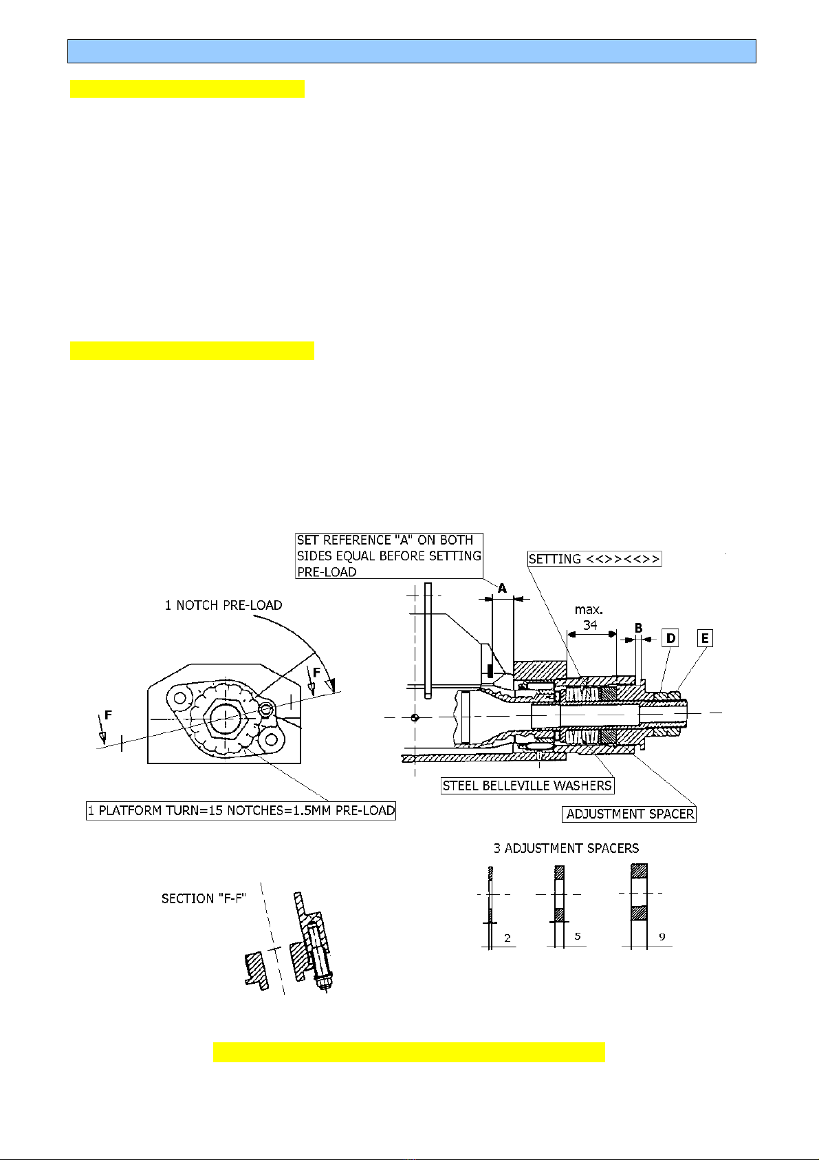
•Clearance between the platform and the rocker (B) shall not be more than 6.5mm when
platform just touches the Belleville stack, with no pre-load.
•The amount of pre-load is the difference between the current and the free length of the
Belleville stack.
•For any Belleville stack, in running condition, rocker lateral motion and the chosen pre-load
must never reach the "Maximum Deflection" (see Table 6), to avoid a sudden lateral locking
of the rocker.
•Once the rocker overcomes the pre-load, the total stiffness reduces to the nominal stiffness
of one Belleville stack. You may like to work within the roll pre-load range under certain
conditions (turn-in…) and wish to pass over the pre-load range in some others (mid-corner,
curbs…). Set accurately the transition point (pre-load level) between the two conditions, since
the stiffness change is sudden and affects transient car behaviour.
You can achieve a progressive load / displacement characteristic by combining in series two different
stacks or a regressive load / displacement ratio by fitting an appropriate pre-load. Total length of
any stack should be maximum 34 mm.
BELLEVILLE STACK CONFIGURATIONS (Belleville thickness 2.0mm)
Stack configuration Max deflection
mm Stack width
mm Nominal stack stiffness
Kg/mm (no pre-load) Maximum
notches
<<<<>>>> 1.12 17.50 2504 8
<<<>>> 1.12 13.50 1796 8
<<<>>><<< 1.69 20.25 1197 12
<<>><< 1.69 14.25 761 12
<<>><<>> 2.25 19.00 571 17
<<>><<>><< 2.81 23.75 457 22
<>< 1.69 8.25 362 14
<><> 2.25 11.00 272 17
<><>< 2.81 13.75 218 22
<><><> 3.37 16.50 181 26
<><><>< 3.93 19.25 155 28
<><><><> 4.50 22.00 136 34
<><><><><> 5.62 27.50 109 44
Note: the front rocker lateral movement has been increased from the previous (F399-301) maximum
6mm to about 10mm on the F302/3/4 car.

PRE-LOAD SETTING PROCEDURES 10
DOUBLE STIFFNESS PRE-LOAD
•Mount the stack you want to use and turn the platform until in contact with the Belleville
stack
•Turn the platforms until distance A is the same on both sides
•Check distance B to be less than 6.5mm, if more, replace adjustment spacer
•Mark this platform position as the “zero pre-load” notch
•Turn both left and right platforms the amount of notches to set the desired pre-load.
One turn of platform is 15 notches corresponding to 1.5mm displacement
(1 notch = 0.1mm)
INFINITE STIFFNESS PRE-LOAD
•Set the pre-load as described for the double stiffness procedure here above
•Mount nut D in contact with the platform
Tighten counter nut E against nut D (check nut D stays against the platform)
Twin-damper system information is on page 38

11 FRONT SUSPENSION ROLL CENTRE SETTING
Front roll centre height can be changed by moving the spacer to its upper or lower position on the
wishbone spherical joint. When choosing "low roll centre" configuration, push-rod length has to be
shortened by 1.2 register turns ( 7 faces of the adjuster) to keep the car at the same ride height..
When adjusting the roll centre height camber gain versus wheel travel varies a little.
OPTION Roll centre height
@ static ride height Camber change
with 10mm wheel travel
Std X 5’
Low -10 mm 3’
STEERING ASSEMBLY
Pinion primitive diameter 15.60 mm
Static steering ratio 13.1 steering wheel/wheel
Ackermann [%] 29


13 REAR SUSPENSION
REAR SUSPENSION ROLL CENTER AND ANTISQUAT SETTING
Option D-1 and E-2 alter caster angle. To obtain std value shorten by 2 turns the ‘caster’
uniball.Option B-2 needs special bracket for front top mounting (available at Dallara).
OPTION Roll centre height Camber change Antisquat
@ static ride height with 10mm wheel travel %
A-1 Std 20’ 48
B-2 -18 16’ 48
C-1 +18 24’ 48
*D-1 std 23’ 66
*E-2 -15 18’ 66
F-1 +8 22’ 35
G-2 -10 18’ 35

REAR ANTIROLL BAR STIFFNESS 14
F302/3 features a rear anti-roll bar with two adjustable blades, long 80mm.
Ø 40mm is the biggest possible RARB, Ø13mm is the softest RARB available.
The two digits in this table represent the blade positions: 1=full soft, 5=full stiff.
Stiffness in kg/mm. Note: P1-P5 = P3-P3 = P2-P4
Ø 13 Ø 14 Ø 16 Ø 19 Ø 21 Ø 22 Ø 24 Ø 26 Ø 28 Ø 30 Ø 35 Ø 40
P1-P1 15.7 19.9 29.4 44.6 53.8 57.8 65.0 70.6 75.1 78.7 84.5 87.7
1-2 15.8 20.2 30.0 45.9 55.7 60.1 67.9 74.1 79.0 83.0 89.5 93.0
2-2 16.0 20.4 30.6 47.4 57.8 62.5 71.0 77.8 83.3 87.7 95.0 99.0
1-3 16.3 20.8 31.5 49.5 61.1 66.3 76.0 83.8 90.2 95.5 104.1 108.9
2-3 16.4 21.1 32.1 51.2 63.6 69.3 80.0 88.7 95.8 101.8 111.7 117.3
1-4 16.7 21.5 33.1 53.7 67.6 74.1 86.3 96.6 105.1 112.3 124.5 131.4
1-5 16.9 21.8 33.8 55.7 70.7 77.8 91.5 103.1 112.8 121.2 135.5 143.8
2-5 17.0 22.1 34.6 57.8 74.1 82.0 97.3 110.5 121.8 131.6 148.7 158.7
3-4 17.3 22.6 35.7 61.0 79.6 88.7 106.9 123.0 137.2 149.8 172.3 185.9
3-5 17.5 22.9 36.6 63.5 83.9 94.2 114.9 133.8 150.7 166.0 194.2 211.5
4-4 17.8 23.4 37.9 67.5 91.0 103.1 128.4 152.5 174.9 195.8 236.3 262.5
4-5 18.0 23.8 38.8 70.6 96.7 110.5 140.2 169.3 197.5 224.5 279.4 316.8
5-5 18.2 24.2 39.8 74.0 103.2 119.1 154.3 190.4 226.7 263.1 341.7 399.4
REAR SUSPENSION ROCKER REPLACEMENT
Rear rocker spins around the steel pivot A fitted onto the gearbox case by the stud B, fixed
with LOCTITE 242™. The following procedure shows the disassembly of the rocker and the
pivot A. Contact DALLARA customer’s service regarding the special tools E and F.
•Unscrew the nut C. The tightening torque to fit it back is 3.5 Kgm;
•Take off the top cap and the rocker;
•Unscrew nut D with a long 14mm tubular spanner. The tightening torque to fit it back is
5.5 Kgm;
•Fit extractor F around pivot’s outer flange and by screwing in bolt E you will extract the
pivot;
•Remove stud B with the proper tool. The stud is fitted with Loctite in its insert. When
removing the stud, heat up the stud’s thread to break the Loctite with a heatgun up to
140°C.

15 POWER FLOW DIFFERENTIAL
This differential is designed with versatility as its major asset. Many parameters will lead
you to the required setting. A car with good grip and low power may require a completely
different arrangement than that required for a high power/low grip car.
Working principles: Ten friction plates within the diff, six connected to the side gears, four to the
diff casing, control the amount of ‘differential’ action available. The amount of limited slip depends
only on the frictional resistance between these ten plates.
Four factors contribute in defining this frictional resistance:
1. The bevel gears thrust apart as soon as the car moves. This is a feature of bevel gears and is not
adjustable. The contribution of this on friction is minimal.
2. The ramp angle on the side gear ring influences the amount of the driving force on the diff that gets
directed sideways and onto the plates. E.g., on the power/drive side ramp, 60 degrees transmits less force
sideways than a 30 degree ramp. Likewise, on the off-power side ramp, an 80 degrees angle will transmit
little force while 45 degrees locks more. 60°/80° is fitted as standard;
3. The pre-load with which they are assembled to start. In each diff there is a pre-load spacer that looks like
one of the B plates, but thicker. Depending on diff model, it is either the first or the last component
assembled into the diff casing. Its thickness dictates to what degree the plates are pre-loaded / forced
against each other. The pre-load is set and checked on each diff by holding one side gear locked, via a
dummy output shaft held in a vice, and by turning the other with a torque wrench. If the measured
resistance is deemed too high, the spacer is ground down until the desired figure is achieved. The figure
should be checked periodically as it tends to reduce as the diff runs, meanwhile a new A, slightly thicker
spacer will allow re-setting;
4. The final and easiest adjustment is the re-arrangement of the contact order of the friction discs. The
arrangement 1, with a disc succession A, B, A, B, A, has the maximum number of working friction faces. It
gives the maximum resisting torque. The arrangement 3 has the minimum of working friction faces and
gives the minimum resisting torque.
Standard Hewland available ramp angles are: 30/60; 45/45; 45/80; 60/80; 80/80
Differential settings have an important influence on the cars’ balance, especially on corner turn-in and exit.
•The torque on the differential in drive (acceleration) is much bigger than the torque on the differential
given by the engine brake (deceleration). Typical in line acceleration gets to about 1g, off-
power/braking by the engine only gets typically up to 0.3g.
•The disc configuration (2, 4 or 6 faces) has the same effect on drive and off-power, the ramps are the
only tool to differentiate the friction force or ‘lock’ between drive and brake.
•The discs wear off, just as a clutch, and should get checked regularly. This also means that the pre-
load is ‘wearing’ down, especially when using the 2 friction discs configuration.
•Pre-load is kind of a ‘constant lock’ and the effect is felt in slow and fast corners in entry, mid-corner
and exit. The ramps and disc configurations have more effect in slow and less in fast corners, and
affect corner entry and exit, less so mid-corner.
•Pre-load blocks the differential (both wheels turn at the same speed) until the difference in torque is
bigger than the pre-load. Once passed the pre-load, the remaining lock is achieved by the ramps and
disc configuration only.
•Most circuits require little lock to prevent the inner wheel from spinning coming out of the corners,
depending though on tyres, track, driving style and weather conditions. Excessive lock might result in
power understeer.
•Some amount of lock in off-power helps to stabilize the rear end, excessive lock might cause turn-in
understeer.
This table shows the % of lock from minimum to maximum lock.
Lock%= (slower wheel torque – faster wheel torque)/ total torque
LOCK% 2.5 5.0 7.0 9.5 11 12.0 15.5 18.0 24.0 25.0 33.5 42.0 44.0 55.0 68.5
RAMP 80 80 70 80 70 60 70 60 45 60 45 30 45 30 30
DISCS 2 4 2 6 4 2 6 4 2 6 4 2 6 4 6
60/70 and 70/80 ramps are available at Dallara Automobili S.r.l.

DIFFERENTIAL LAY-OUT 16
•Check the plate arrangement is equal on both sides.
•Side gear ring, diff end plate, diff wall and pre-load spacer all act as “B” plates
•A bigger ramp angle transmits less thrust onto the plates than a smaller ramp angle.

17 DAMPERS
DAMPER DIMENSIONS
Standard dampers are KONI 2812-140. Front and rear have the same open length and identical
installation parts. Damper assembly dimensions are:
mm
full open length 335
full closed length FRONT 299
REAR 291
Stroke FRONT 36
REAR 44
On Koni dampers you should always use the 8mm Teflon spacer on front assembly to prevent the
rocker to lock. If you plan to use alternative products check that maximum stroke to be less than 36
mm.
Dallara, on request, delivers installation kits for PENSKE and QUANTUM dampers. If you want to
install other dampers, remind that full open and closed length must be equal to those listed above.

DAMPER GRAPH 18
KONI 2812/140
-100
-80
-60
-40
-20
0
20
40
60
80
100
0 20 40 60 80 100 120
V (mm/s)
F (kg)
BUMP min BUMP max REBOUND min REBOUND max

19 RIDE HEIGHT CHECK AND REFERENCES
•Ride height is fundamental for setting and changing the aerodynamic balance of the
car.
•A lower car generally generates more down-force than a higher car.
•A lower car improves performance as it features a lower centre of gravity.
•The easiest way to measure ride heights is checking the FR and RR distances
between the floor wood and the set-up floor, preferably with the driver on board and
tyres at hot tyre pressure. This is the only method which takes into account the ride
height changes caused by wear on the floor wood.
It might sometimes be difficult to measure ride heights directly, so we also provide alternative
references.
The example shows front ride height 15mm and rear 30mm (at wheel axis).
With 2675mm wheelbase, this gives 0.32 ° pitch angle. [(30 – 15) / 2675] x 57.29 = 0.32°
At the front end of the car you have two alternative references:
•Two round platforms 513.5mm from car bottom, on top of the tub at the wheel axle line.
You can measure their distance from the ground as 528.5-513.5 = 15mm ride height
•A flat surface (skid) about 310 mm behind the wheel axis and 40 mm behind the skid
leading edge. Measure its distance from ground as 16.7 - (tan0.32°*310)=15mm
At the rear end of the car you have two alternative references:
•Two machined areas, at 328.5 mm from car bottom, on the gearbox at wheel axle line. You
can measure their distance from the ground as 358.5 – 328.5 = 30mm height
•Under the flat bottom, about 310 mm ahead of rear wheel axis and 50mm ahead of the start
of the diffuser. Measure and calculate its distance from ground as
(tan0.32° *310) + 28 (measured)= 30mm height
REAR RIDE HEIGHT FRONT RIDE HEIGHT
30mm 15mm

FRONT WING 20
FRONT WING CONFIGURATIONS
FRONT WING SIDEPLATE HOLES
This manual suits for next models
2
Table of contents
Other dallara Automobile manuals