dallara F308 User manual

DALLARA F308
Manual F308 CONTENTS VR -03
CAR VIEWS 3
CAR INFO 4
SET-UP 5-6
SUSPENSION Front 7-12
Rear 13-14
DIFFERENTIAL 15-16
DAMPERS 17
RIDE HEIGHT 18
AERODYNAMICS 19-23
COOLING 24-25
UPRIGHT ASSEMBLY 26-27
SYSTEMS Oil 28
Brakes 29
Fuel 30
Extinguishers 31
GEARBOX 32
SAFETY AND UTILITY NOTES 33
TIGHTENING TORQUES 34
CONVERSION TABLE 35
GENERAL AGREEMENT
FIA Homologation document 36
37-40

DALLARA F308
DALLARA AUTOMOBILI IS HAPPY WITH THE CHOICE YOU MADE BUYING
THE DALLARA F308. WE WISH YOU THE VERY BEST IN RACING IT.
Dallara Automobili
Via Provinciale 33
43040 VARANO MELEGARI – PR – ITALY
Telephone +39 0525 550 711
Belgium office +32 12 210 208
spares Ms David Beck Email [email protected]
On the Dallara web site www.dallara.it you can find useful information about the company,
our people and the factory. It also includes a ‘second hand’ cars service.
Our web site also includes information for customers only, in the restricted area. David
Beck hands out the necessary pass-words.
For any question, advice or idea you might have, please don’t hesitate to contact us.
DALLARA SPARE PARTS DISTRIBUTORS
JAPAN ENGLAND EURO SERIES GERMAN CUP
contact Shiro Matsunaga Martin Stone Tine Schwadtke
Tel +81 550 885 550 +44 1252 333 294 +49 3544 50030
e-mail matsunaga@
lemans.co.jp [email protected] [email protected]

3SIDE & TOP VIEW OF THE F308

GENERAL DIMENSIONS AND SUPPLIER 4
wheelbase 2730 mm
front track 1585 mm
rear track 1535 mm
overall length 4264 mm
overall width 1835 mm [tire-tire front]
overall height 950 mm [roll hoop]
weight 540 kg incl. driver & ballast
front suspension pushrod twin damper system
rear suspension pushrod twin damper system
SUPPLIERS
chassis carbon sandwich with AL/Nomextm honeycomb
bodywork Glass fibre composite with Nomextm honeycomb
composites Delta preg
castings Magnesium World
gearbox Hewland, sequential, six forward gears + reverse
g-box internals Hewland gears and differential
springs Eibach 3“/36mm ID
dampers Koni 2812 bump and rebound adjustable
fuel cell Premier – FT3
extinguisher Lifeline (electric operated)
steering wheel Sparco
quick release SPA-Design
wheels Taneysia 9”front & 10.5”rear
brakes Brembo
battery Deka
seat belts TRW-Sabelt
Honda Mugen XJ6 Mugen & NBE
Mercedes HWA
Nissan Tomei
Volkswagen Spiess
Toyota Tom’s & Torii
Installed
engines
Toyota Piedrafita

5 SET-UPS PER TYRE MAKE
These set-ups consider the complete car with the driver seated in it, ready to race.
FRONT AVON BRIDGESTONE KUMHO DUNLOP
ride height (mm) 18 16 16 15
spring (Lb/in) 900 850 800 900
spring pre-load the basic set-up does not suggest the use of spring pre-load
pushrod length use the pushrod adjuster to set the ride height
roll centre setting std lower std Std
ARB (kg/mm) 35 60 90 35
camber 3,00° 3,50° 3,25° 3,50°
caster-WMP 10,60° 11,00° 10,00° 10,60°
caster-UMP/P-15 12,50° 13,50° 12,50° 13,50°
toe (mm total) 3,00 OUT 3,00 OUT 2,00 OUT 3,00 OUT
REAR
ride height (mm) 35 32 34 35
spring (Lb/in) 800 800 700 800
spring pre-load avoid using rear spring pre-load
pushrod length use the pushrod adjuster to set the ride height
roll centre setting A-1 A-1/F-1 E-2/G-2 A-1
ARB (kg/mm) 60 75 120 90
camber 2,50° 2,25° 2,50° 3,00°
toe 1,00 IN 2,00 IN 1,00 IN 2,00 IN
Differential 70/60 4F 60/80 6F 60/60 4F 60/80 4F
Notes:
¾Ride heights are measured at the axles
¾When using spring pre-load you can lower the front ride height
¾ARB values are those as you can find in the following pages
¾Caster WMP means caster on the suspension with the pushrod mounted on the wishbone
¾Caster UMP/P-15 means caster on the suspension with the pushrod mounted on the upright,
in position P-15 [see later in the manual]
¾Toe is measured at the wheel rim’s, total value means left and right wheels added
¾Differential, see following pages.
Comments:
¾In fast corners aerodynamics (ride heights and wing settings) have more influence on the
balance than in slower corners.
¾In mid-and slow speed corners the weight distribution and the differential settings are the
most important contributors to the balance of the car.
¾Tune the dampers to the chosen springs, not the springs to the dampers.
¾Always pay attention to reach enough high tyre temperatures. No car can reach its limit on
too cold tyres. No car can be reasonably balanced with a significant difference between front
and rear tyre temperatures.
¾Run the car always as low as possible, although without going stiffer on springs for running
lower.

SETUP ADJUSTMENTS 6
Effects of the adjustments on the cars’ set-up.
Positive change in: means:
Height car rises
Toe toe-out
Camber upper part of rim outward
Castor lower part of rim points ahead
FRONT REAR
PUSHROD ADJUSTER
Height change (mm) 4.096 6.413
1TURN Camber change (deg) 1’ 12’
Thread step 24/”R+24/”L=2.12mm 20/”R+24/''L=2.32mm
TOE ADJUSTER (PER WHEEL)
Height change -3.37mm
Camber change -18’3”
1TURN toe change (deg) 37’72” -45’27”
thread step 24/”=1.06mm 20/”R+24/”L=2.32mm
CAMBER SPACER +1mm
height change
toe change
17’33”
0.38mm
24’47”
1.87mm
11’= + 1/4Turn
CASTOR ADJUSTER 23° brake calliper=16°
Castor change (deg) 29’41” -36’00”
thread step 24/''=1.06mm 24/''=1.06mm
1TURN height change (mm) -1.427 -0.4
camber change (deg) -4'34” 2'40”
toe change (deg) 0 -1'30”
SPRING PLATFORM
+1TURN thread step (mm) 2 2
height change (mm) 2.29 2.61
WHEEL/SPRING RATIO (vertical) 1.131 1.299
ARB/WHEEL RATIO See table 1.884
ROLL CENTRE HEIGHT Tyre dependent Tyre dependent
¾Spacers to adjust camber are available in the following thickness: FRONT: 1.0, 1.5 and 2.0
mm. REAR: 0.8, 1.0, 1.2, 1.5 and 2.0mm. Combine these to make fine adjustments.
¾Front and rear wheel to spring, front and rear wheel to drop link motion ratios may be
considered as constant for typical wheel travel.
¾For a given ride height the F308 front roll centre is 15mm higher compared the F305.
¾The front roll centre is adjustable by moving the spacer between the upright and the lower
wishbone. More information further in this manual.

7 FRONT SUSPENSION
VERTICAL PRELOAD ADJUSTMENT
Remind there is always some ‘pre-load’ in the damper: typically this is 24-27kg for the
standard Koni damper. This ‘pre-load’ depends on damper make/type and comes mainly
from the internal gas pressure.
In a non pre-load condition, as long as the damper is not fully extended, turning on the
spring platform changes the car ride height (and lowers the gas pressure inside the
damper). When the damper gets fully extended, turning on the platform increases vertical
spring pre-load on the car. We advise though, not to proceed this way, because some
dampers [including Koni] should not be used fully extended. Therefore we advise to use the
droop-stop for limiting rebound travel or applying spring pre-load.
Pre-load in this text is considered to be the necessary force that has to be applied to the
spring to change its length with respect to the static length value.
P = Ks x t x 2
P = pre-load in kg
Ks = spring stiffness in kg/m [(Ks in Lb/in) / 56 = Ks in kg/mm]
T = number of spring platform turns
2 = mm / turn (for standard Dallara Koni damper top)
SETTING PRE-LOAD
¾Mount the damper-spring combination with the spring platform just in contact with
the spring
¾Put the car including the driver on the set-up floor
¾Clear the droop-stop from touching the rocker
¾Adjust ride height with the pushrod adjusters to the desired setting [further correct
for corner weights at this point]
¾Bring the droop-stop in contact with the rocker
¾Now turn the spring platform to achieve the desired pre-load
PUSH ROD ADJUSTER
DROOP STOP
ROCKER

FRONT CASTOR ANGLE SETTING 8
When the car is flat, that is with the same front and rear ride height:
¾WMP: when the upright inclination angle (apparent castor) is +2.10° the castor angle (build
in castor) is 10.60°. The upright reference plane points downwards in forward direction.
¾UMP: when the upright inclination angle (apparent castor) is -2.80° the castor angle (build in
castor) is 13.50°. The upright reference plane points upwards in forward direction.
Drawing shows UMP
CASTOR 13.50°
HORIZONTAL
UPRIGHT
REFERENCE
TRAVEL DIRECTION
When the car has a pitch angle, that is with different front and rear ride height.
For instance, with FRH 15mm and RRH 30mm the pitch angle equals:
[(30-15)/2730] x 57.29 = 0.31°
¾WMP: the upright inclination angle (apparent castor) is 2.10° + 0.31° = 2.41° and the
castor angle (build in castor) becomes 10.60° - 0.31° = 10.29°.
¾UMP: the upright inclination angle (apparent castor) is -2.80° + 0.31° = 2.49° and the
castor angle (build in castor) becomes 13.50° - 0.31° = 13.19°.
REAR
The rear wheel ‘castor’ angle can be measured to check bump steer to be zero. You can measure
the angle on the brake calliper mounting platforms. When the car is flat (front ride height is equal to
rear ride height) and you measure ‘apparent’ castor of 23°, the ‘castor’ angle is 16° and bump steer
is zero.
The castor angle on the rear axle is, other than for the bump steer control, not relevant since the
rear wheels are not turning.

9 FRONT ANTI-ROLL
The drawings shows both motion ratio’s
STIFF
SETTING
SOFT
SETTING
The TABLE below shows the motion ratio’s for all ARB’s and different blades available. Two multiple
position ARB’s are available too.
RATIO = WHEEL/ARB [WHEEL vertical travel / ARB drop link travel]
ADJUSTABLE BLADE ARB
BLADE LENGTH
[mm]
SOFT
SETTING
STIFF
SETTING
PART
ITEM CODE
270 1.187 0.998 30255050
245 1.207 1.012 30555083
221 1.227 1.027 30555031
170 1.272 1.058 T0245066
115 1.324 1.093 30255129
MULTIPLE POSITIONS ARB
1.276 1.059
1.295 1.073
1.315 1.087
1.336 1.102
ARB 5P
1.357 1.118
30555068
1.239 1.031
1.255 1.044
1.272 1.056
1.290 1.069
1.308 1.082
1.326 1.095
ARB 7P
1.345 1.109
30755068
BLADE LENGTH: total blade length in
mm
, measured between extremities.
SOFT SETTING:
¾use the fixation point close to the rocker axle
¾for a given ARB travel the WHEEL must travel more compared
with the STIFF SETTING
STIFF SETTING:
¾use the fixation point further away from the rocker axle
¾for a given ARB travel the WHEEL will travel less compared with
the SOFT SETTING

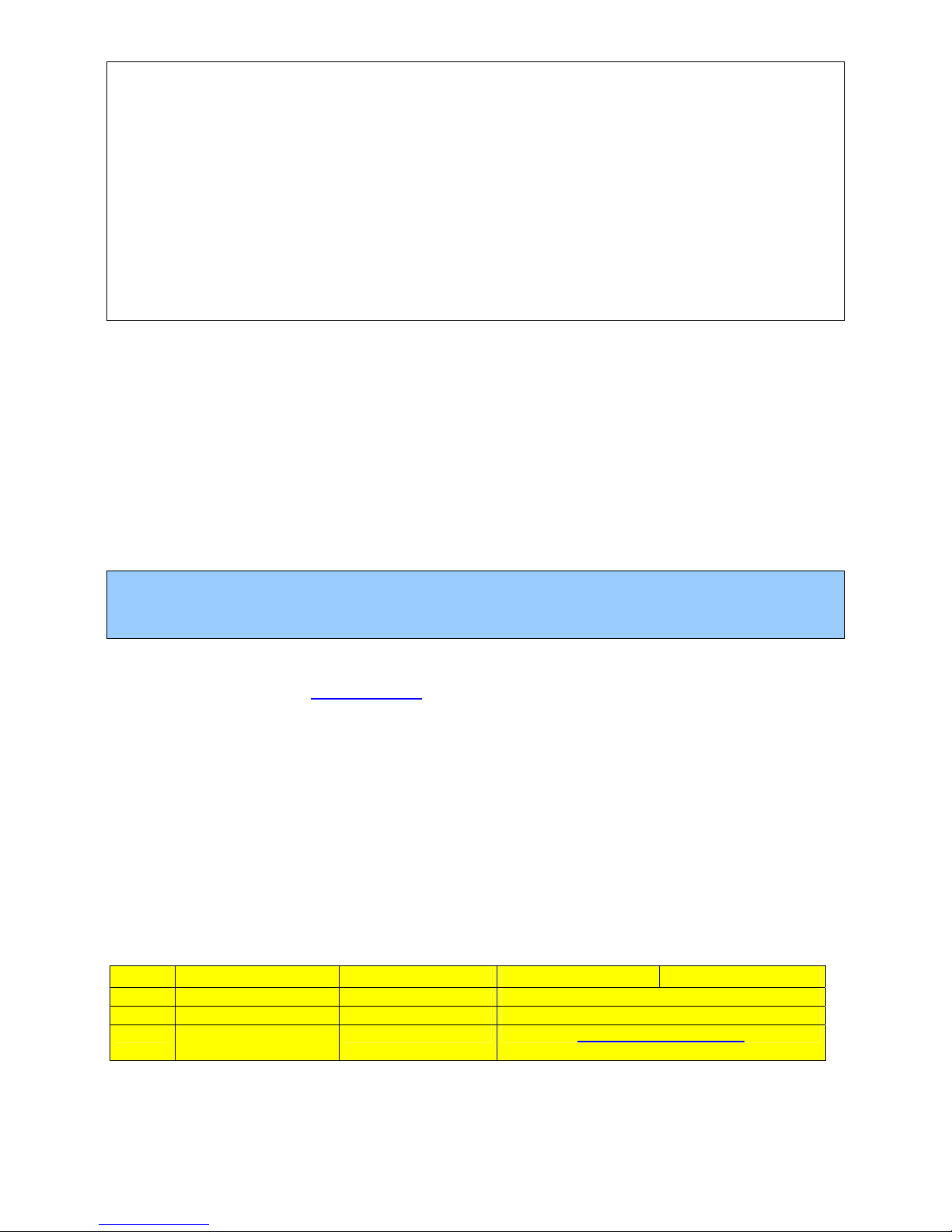
FRONT ROLL BAR VALUES 10
¾The values shown below are in kg/mm [daN/mm] at one end of the blade while the other end
is locked.
¾The values below are measured on the ARB isolated from the car. You may use the Motion
Ratio’s from page 5 to calculate the ARB stiffness
at ground
.
¾On various ARB’s we suggest not to use the 115mm blade.
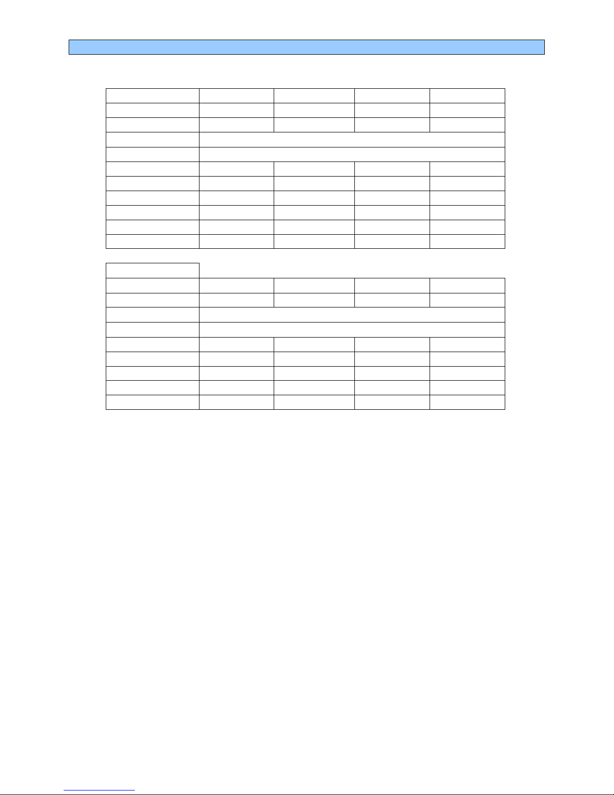
ARB BLADE BLADE POSITION
1 2 3 4 5
T-13 solid B-270 3,0 3,1 3,4 3,9 4,0
B-245 3,8 3,9 4,2 4,7 4,8
B-221 5,0 5,1 5,4 5,9 6,0
B-170 10,0 10,2 10,7 11,4 11,6
B-115
T-18x2,5 B-270 5,5 6,0 7,4 9,4 10,0
B-245 6,9 7,4 9,0 11,1 11,8
B-221 9,5 10,1 11,8 14,2 15,0
B-170 21,0 22,2 25,7 30,5 32,0
B-115
T-20x2,0 B-270 6,5 7,1 8,7 10,8 11,5
B-245 8,0 8,6 10,4 12,7 13,5
B-221 11,0 11,8 13,5 17,0 18,0
B-170 24,0 25,3 28,9 33,9 35,5
B-115
T-30x5,0 B-270 8,5 10,7 17,1 25,7 28,5
B-245 11,1 13,8 21,7 32,3 35,8
B-221 16,0 19,4 29,3 42,7 47,0
B-170 41,5 47,8 66,2 91,0 99,0
B-115 187,0 190,0 198,5 210,0 213,8
6 7
5 POINTS ARB 30x2,0 70,0 99,0 150,0 250,0 545,0 - -
7 POINTS ARB 25x2,0 26,5 33.9 44.4 60.3 85.5 129.0 213,1
¾Since there have been some quality problems with the
T 13 Solid
we replaced this ARB by a
slightly stiffer new ARB, the T-14.5mm Solid. In its softest position with the 270 blade the
stiffness is 4,1kg/mm, in its stiffest position using the 170 blade the stiffness is 16,1kg/mm.
-

11 FRONT SUSPENSION TYPES
The F308 car has two different options for its front suspension.
¾WMP [Wishbone Mounted Pushrod]: This is a conventional suspension with the pushrod
mounted on top of the lower wishbone. This suspension is only in detail different from the
front suspension on our previous F3 car.
¾UMP [Upright Mounted Pushrod]: In this suspension the pushrod is mounted on the upright.
The pushrod position is adjustable in longitudinal sense. Extra load is transferred to the
corner front inner wheel, potentially reducing understeer thanks to a more equal vertical load
between front inner and outer wheels.
Between both suspensions the following parts are different:
¾Lower wishbone
¾Ackermann arm
¾Lower part of the pushrod
¾Additional bracket for UMP
For the UMP suspension we have foreseen 4 different positions [in longitudinal sense] to increase or
decrease the effect typical of this suspension lay-out. Two different brackets give a total of four
positions. We call these positions according the distance they are set behind the front axle line.
Positions:
¾P -5(mm) [on standard bracket]
¾P -10 [on optional bracket]
¾P -15 [on standard bracket]
¾P -20 [on optional bracket]
There are various ways to express the difference between the 4 positions, we choose one that clearly
shows the level of effect.
¾P -5 transfers ‘X’ load to the corner inner front wheel
¾P -10 transfers 70% more compared P -5mm
¾P -15 transfers 130% more compared P -5mm
¾P -20 transfers 170% more compared P -5mm
Further information:
¾The effect on load transfer [by turning steering wheel] of the standard geometry with ‘typical’
caster is near identical to the effect on load transfer on the UMP P -5
¾In a straight line the UMP behaves identical compared to a conventional WMP front
suspension. UMP’s effect increases with steering angle. Therefore the effect is most
noticeable in slow corners.
¾All 4 positions cause an increase of steering force, P -20 being the heaviest of the 4 positions.
¾All positions cause an increased load transfer on the rear axle opposite in direction compared
to what occurs on the front axle. This will decrease traction capacity, P -20 causes the
largest load difference between rear inner and outer wheel.
¾Roll centre height, camber, camber change, steering ratio, damper ratio, ARB ratio,
Ackermann, off-set and trail do not vary between the 4 positions. When changing the
pushrod position always check the front ride height, the only [other]feature that varies
between different positions.

FRONT ROLL CENTRE SETTING and STEERING 12
Front roll centre height can be changed by moving the spacer relative to the wishbone spherical
joint.
When you change to ´low roll centre´ configuration the push-rod length has to be shortened by 1.2
register turns ( ≈7 faces of the adjuster) to put the car back at the same front ride height.
When adjusting the roll centre height camber gain versus wheel travel varies a little.
OPTION Roll centre height
@ static ride height Camber change
with 10mm wheel travel
Std X 3’
Low -14.0 mm 5’
6mm
6mm
The drawing shows the roll centre setting on WMP. The procedure and effect are identical on UMP
suspension.
Note that the spacer is now 6mm high, compared to 5mm on our previous cars.
STEERING
Pinion primitive diameter 15.60 mm
Static steering ratio 12.5° steering wheel/1°wheel
Ackermann [%] 28

13 REAR SUSPENSION
REAR SUSPENSION GEOMETRY
CFG Roll centre
height Camber change Anti-rise Anti-squat To adjust ‘caster’
adjust joint
@ static ride height with 10mm wheel travel % % + means longer
A-1 std 20’ 7 49 -
*B-2 -19 16’ 7 49 -1.0 turns
C-1 +17 24’ 7 49 -
*D-1 std 23’ 69 69 -0.5 turn
*E-2 -20 18’ 69 69 -1.5 turns
F-1 +9 22’ 22 36 +1.5 turns
G-2 -10 18’ 22 36 -
Note:
¾B-2 needs special brackets for the front top mounting (available from Dallara).
¾D-1 and E-2 effect the ‘caster’ angle.

REAR ANTIROLL BAR 14
The F308 has rear anti-roll bars with twin adjustable blades, their length is 80mm.
Ø 40mm is the biggest possible RARB, Ø13mm is the softest RARB available.
The two digits in this table represent the blade positions: 1=full soft, 5=full stiff.
Stiffness in kg/mm from the isolated ARB. One blade is fixed while the other blade displaces 1mm.
The hollow 30x3mm ARB is equal to std Ø26mm P1-P5 ≈P3-P3 ≈P2-P4
Ø 13 Ø 14 Ø 16 Ø 19 Ø 21 Ø 22 Ø 24 Ø26/30* Ø 28 Ø 30 Ø 35 Ø 40
P1-P1 15.7 19.9 29.4 44.6 53.8 57.8 65.0 70.6 75.1 78.7 84.5 87.7
1-2 15.8 20.2 30.0 45.9 55.7 60.1 67.9 74.1 79.0 83.0 89.5 93.0
2-2 16.0 20.4 30.6 47.4 57.8 62.5 71.0 77.8 83.3 87.7 95.0 99.0
1-3 16.3 20.8 31.5 49.5 61.1 66.3 76.0 83.8 90.2 95.5 104.1 108.9
2-3 16.4 21.1 32.1 51.2 63.6 69.3 80.0 88.7 95.8 101.8 111.7 117.3
1-4 16.7 21.5 33.1 53.7 67.6 74.1 86.3 96.6 105.1 112.3 124.5 131.4
1-5* 16.9 21.8 33.8 55.7 70.7 77.8 91.5 103.1 112.8 121.2 135.5 143.8
2-5 17.0 22.1 34.6 57.8 74.1 82.0 97.3 110.5 121.8 131.6 148.7 158.7
3-4 17.3 22.6 35.7 61.0 79.6 88.7 106.9 123.0 137.2 149.8 172.3 185.9
3-5 17.5 22.9 36.6 63.5 83.9 94.2 114.9 133.8 150.7 166.0 194.2 211.5
4-4 17.8 23.4 37.9 67.5 91.0 103.1 128.4 152.5 174.9 195.8 236.3 262.5
4-5 18.0 23.8 38.8 70.6 96.7 110.5 140.2 169.3 197.5 224.5 279.4 316.8
5-5 18.2 24.2 39.8 74.0 103.2 119.1 154.3 190.4 226.7 263.1 341.7 399.4
REAR SUSPENSION ROCKER REPLACEMENT
The rear rocker spins around a steel pivot (A) fitted into the gearbox case by the stud B, fixed with
LOCTITE 242™. The following procedure shows how to extract the rocker and the pivot. Contact
DALLARA customer’s service regarding the special tools E and F.
•Unscrew nut C and take off the cap and rocker. (Tightening torque for nut C is 3.5 Kgm)
•Unscrew nut D with 14mm tube spanner. (Tightening torque for nut D is 5.5 Kgm)
•Fit extractor F around pivot’s outer flange. By winding on bolt E the pivot will come out.
•Remove stud B with the proper tool. The stud is fitted with Loctite in its insert. When removing
the stud, heat the stud to about 140°C to break the Loctite.

15 POWER FLOW DIFFERENTIAL (Hewland)
This differential is designed with versatility as its major asset. Many parameters will lead you to the
required setting. A car with good grip and limited power requires a very different arrangement than
that required for a high poor grip/high power car.
Working principles: Ten friction plates within the diff, six connected to the side gears, four to the diff
casing, control the amount of ‘differential’ action. The amount of
limited slip
only depends on the friction force
between these ten plates.
Four factors contribute to the level of this friction force:
1. The bevel gears thrust apart as soon as the car moves. This is a feature of bevel gears and is not
adjustable. The contribution of this on friction is minimal.
2. The ramp angle on the side gear ring influences the amount of the driving force on the diff that gets
directed sideways and onto the plates. E.g. on the power/drive side ramp, 60 degrees transmits less force
sideways than a 30 degree ramp. Likewise, on the off-power side ramp, an 80 degrees angle will transmit
little force while 45 degrees locks more. 60°/80° is fitted as standard;
3. The pre-load with which they are assembled to start. In each diff there is a pre-load spacer that looks like
one of the B plates, but thicker. Depending on diff model, it is either the first or the last component
assembled into the diff casing. Its thickness dictates to what degree the plates are pre-loaded / forced
against each other. The pre-load is set and checked on each diff by holding one side gear locked, via a
dummy output shaft locked in a vice, and by turning the other with a torque wrench. If the measured
resistance is deemed too high, the spacer is ground down until the desired figure is achieved. The preload
should be checked periodically as it tends to reduce as the diff runs, meanwhile a slightly thicker spacer will
allow re-setting;
4. The re-arrangement of the order of the friction discs. The arrangement 1, with a disc succession A, B, A, B,
A, has the maximum number of working friction faces. It gives the maximum resisting torque. The
arrangement 3 has the minimum of working friction faces and gives the minimum resisting torque.
Standard Hewland available ramp angles are: 30/60; 45/45; 45/80; 60/80; 80/80; optional: ramps including 70
Differential settings have an important influence on the car’s balance throughout the corner. Also handling is
affected, especially so on corner turn-in and exit.
¾The torque on the differential in drive (acceleration) is much bigger than the torque on the differential
given by the engine brake (deceleration). Typical in line acceleration gets to about 1g starting from a
relatively low speed, off-power/braking by the engine only gets typically up to 0.3g.
¾The disc configuration (2, 4 or 6 faces) has the same effect on drive and off-power, the ramps are the
only tool to differentiate the friction force or ‘lock’ between drive and brake.
¾The discs wear off, just as a clutch, and should get checked regularly. This also means that the pre-
load is ‘wearing’ down, faster so when using the 2 friction discs configuration and significantly less
when using 6 friction faces.
¾Pre-load is kind of a ‘constant lock’ and the effect is felt in slow and fast corners in entry, mid-corner
and exit. The ramps and disc configurations typically have more effect in slow and less in fast corners,
and affect corner entry and exit, less so mid-corner.
¾Pre-load locks the differential (both wheels turn at the same speed) until the difference in torque is
higher than the pre-load. Once passed the pre-load, the remaining lock is achieved by the ramps and
disc configuration mainly.
¾Most circuits require little lock to prevent the inner wheel from spinning coming out of corners,
depending though on tyres, track, driving style and weather conditions. Excessive lock might result in
power understeer.
¾Some amount of lock in off-power helps to stabilize the rear end, excessive lock might cause turn-in
understeer.
This table shows the % of lock from minimum to maximum lock.
Lock%= (slower wheel torque – faster wheel torque)/ total torque
LOCK% 2.5 5.0 7.0 9.5 11 12.0 15.5 18.0 24.0 25.0 33.5 42.0 44.0 55.0 68.5
RAMP 80 80 70 80 70 60 70 60 45 60 45 30 45 30 30
DISCS 2 4 2 6 4 2 6 4 2 6 4 2 6 4 6

DIFFERENTIAL LAY-OUT (Hewland) 16
¾Always use an equal friction plates arrangement on both sides.
¾Side gear ring, diff end plate, diff wall and pre-load spacer all act as “B” plates
¾A bigger ramp angle transmits less thrust onto the plates than a smaller ramp angle.

17 DAMPERS
DAMPER DIMENSIONS
Standard dampers are KONI 2812-899-925. Front and rear have the same dimensions and identical
installation parts. Damper assembly dimensions are:
Mm
full open length 315
full closed length FRONT & REAR 276
Stroke FRONT & REAR 39
tighten to 55Nm
39mm
3
1
5
m
m
DAMPER GRAPH
This Koni 2812-899-925 is a damper specific for Dallara F3 cars.

RIDE HEIGHT CHECK AND REFERENCES 18
¾Ride height is fundamental to setting and changing the aero balance of the car.
¾A lower car improves performance thanks to its lower centre of gravity.
¾The easiest way to measure the ride heights is checking the FR and RR distances between
the skid block wood and the set-up floor, with the driver on board and tyres at hot tyre
pressure. This is the only method which takes into account the ride height changes
caused by wear on the skid block wood.
It might sometimes be difficult to measure ride heights directly, so we also provide alternative
references.
The example shows front ride height 15mm and rear 30mm (at wheel axis).
With 2730mm wheelbase, which gives a 0.315 ° pitch angle.
At the front end of the car you have two alternative references:
¾Two platforms 558.5mm from the car’s bottom, on top of the tub at the wheel axle.
You can measure their distance from the ground as 573.5 – 558.5 = 15mm ride height
¾The skid block, about 330 mm behind the wheel axis and some 50 mm behind the skid
block’s leading edge. Measure its distance from ground as 16.8 - (tan0.315°*330) =
15mm
At the rear end of the car you have two alternative references:
¾Two platforms, at 335.5 mm from the car’s bottom, on the gearbox at the wheel axle.
You can measure their distance from the ground as 365.5 – 335.5 = 30mm ride height
¾Under the skid block, about 330 mm ahead of rear wheel axis and 50mm ahead of the rear
end of the skid block. Measure and calculate its distance from ground as
(tan0.315° *330) + 28.2 (measured) = 30mm ride height
FRONT AND REAR
REFERENCE
PLATFORMS
REAR RIDE HEIGHT FRONT RIDE HEIGHT
30mm 15mm

19 FRONT WING
FRONT WING CONFIGURATIONS
Note: For medium downforce settings we propose a specific front flap (more narrow than std flap);
the high downforce flap is the standard flap.
Both the Medium Flap and the Standard Flap are identical to those used in 2005 and 2006 [in
2007 the Gurney on the SF was modified].
The front main-plane is supposed to be set at –0.6° [from the car’s floor]
LOW DOWNFORCE
FLAP
ANGLE
MEDIUM AND HIGH
DOWNFORCE -0.6°
FRONT WING SIDEPLATE

REAR WING 20
REARWING PROFILES These 3 profiles are given by the FIA regulations.
REAR WING CONFIGURATION
LDF MDF HDF
REAR WING SIDEPLATE
_____________________
Other manuals for F308
1
Table of contents
Other dallara Automobile manuals