DallasDelta 4GS DOORSTATION User manual

4GS DOORSTATION
This user manual includes a step by quick start guide, Item
checklist, diagrams and specifications.
User Manual
Australian Made
Vandal Resistant
Weather Resistant

CONTENTS
1
2
3
4
5
6
7
8
9
10
SAFETY AND CARE INFORMATION
1. Safety and care information ................................................................................ 3
1.1 Operating environment ..................................................................................... 3
1.2 Mains power supply ........................................................................................... 3
1.3 Pacemakers ......................................................................................................... 3
1.4 Other medical devices ........................................................................................ 3
1.5 Radio transmission equipment ......................................................................... 4
1.6 Potential explosive atmospheres ..................................................................... 4
Important Warning .....................................................................................................4
QUICK START GUIDE
2.0 Quick start Guide ................................................................................................ 5
PRODUCT DESCRIPTION
3.0 Product Description ........................................................................................... 6
PRODUCT FEATURES
4.0 Product Features ................................................................................................ 6
INSTALLATION
5.1 Prior to installation ............................................................................................. 6
5.2 Important information ....................................................................................... 7
CONNECTIONS AND SETUP
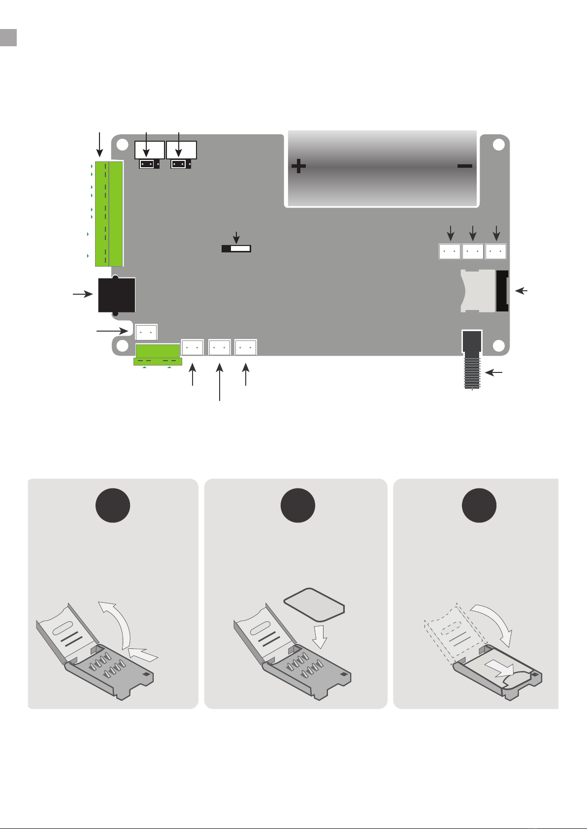
6.1 Internal connections .......................................................................................... 8
6.2 Installing the SIM ................................................................................................ 8
6.3 Battery .................................................................................................................. 9
6.4 Connecting the power supply ........................................................................... 9
6.5 LED indications ................................................................................................. 10
6.6 Powering up ...................................................................................................... 10
OPERATING
7.1 Hands-free ......................................................................................................... 11
7.2 Handset .............................................................................................................. 11
PROGRAMMING
8.0 Programming .................................................................................................... 11
8.1 SMS Programming ............................................................................................ 11
8.2 Keypad Programming ...................................................................................... 12
8.3 DTMF Programming ......................................................................................... 12
8.4 Phone and Phonebook Parameters ............................................................... 12
8.5 Audio Parameters ............................................................................................. 14
8.6 Codes ................................................................................................................. 14
8.7 Options .............................................................................................................. 15
8.8 SMS Settings ...................................................................................................... 16
8.9 Functions ........................................................................................................... 18
PROGRAMMING SUMMARY - QUICK REFERENCE GUIDE
9.1 Phone ................................................................................................................. 20
9.2 Audio .................................................................................................................. 20
9.3 Codes ................................................................................................................. 20
9.4 Options .............................................................................................................. 21
9.5 SMS settings ...................................................................................................... 21
9.6 Functions ........................................................................................................... 21
TECHNICAL SPECIFICATIONS
10.0 Technical Specications ................................................................................. 22
2

1. SAFETY AND CARE INFORMATION
Please read these instructions thoroughly before starting installation. This product must be
installed and maintained only by competent personnel familiar with electrical and telephone
installation.
IMPORTANT! This phone, like any wireless phone, operates using radio signals and the wireless
network, which cannot guarantee connection in all conditions. Therefore, you should never rely
solely upon any wireless phone for essential communications (e.g. medical emergencies).
Remember, to make or receive any calls, the phone must be switched on, appropriately
congured and in an area with adequate cellular signal strength. Emergency calls may not be
possible on all wireless phone networks, when certain network services or phone features are
in use or on phones without a full keypad unless an auto-dial button is programmed to call
an emergency number. Check with local cellular service providers. Emergency calls may be
made even when a SIM card is not installed (subject to network availability) using a recognised
emergency dialling code such as 112.
1.1 Operating environment
Make sure that no special regulation is in force that imposes restrictions on the use of mobile
phones. Restrictions to mobile phones would also apply to this telephone. Most modern
electronic equipment is shielded from radio frequency (RF) signals. However, certain electronic
equipment may not be shielded against the RF signals from your phone.
1.2 Mains power supply
If a mains power supply unit (PSU) is used as the power source for the telephone, it must be
installed by a competent installer and must be provided with a 2-pole disconnect device in
accordance with EN 62368-1 Annex L.
1.3 Pacemakers
Pacemaker manufacturers recommend that a minimum separation of 20 cm (8 inches) be
maintained between a hand-held wireless phone and a pacemaker. The same restriction should
apply to the external antenna of this phone, where tted. If you have any reason to suspect that
interference is taking place, switch o the phone immediately. Hearing aids
The phone’s radio signals may interfere with some hearing aids. In such cases move the antenna
as far away as practical or consult your hearing aid supplier.
1.4 Other medical devices
Operation of any radio transmitting equipment, including the phone, may interfere with the
function of inadequately protected medical devices. Consult a physician or the manufacturer
of the medical device to determine if they are adequately shielded from external RF energy or
if you have any questions. Switch o the phone in health care facilities when any regulations
posted in these areas instruct you to do so. Hospitals or health care facilities may be using
equipment that could be sensitive to external RF energy.
3

WARNING
• Site survey to ensure there is adequate 4G mobile signal coverage
on the selected network. If solar power is a requirement, ensure clear,
unobstructed view of the sky.
• Obtain a suitable SIM card. The SIM card can have a SIM PIN on it and
it will need to be programmed into the unit. If the unit detects a SIM PIN
with no PIN congured, it will halt during initialization and wait for the
PIN conguration. It is recommended to disable voicemail on the SIM.
• Chose a power source. If solar is used, a 5W to 15W panel is required
if not supplied
1.5 Radio transmission equipment
Dallas Delta’s GSM products are designed to conform to international standards regarding the
acceptance of radio frequency interference, certain installation locations may interfere with their
proper operation. We recommend that Dallas Delta GSM equipment is not installed in close
proximity to any equipment that generates RF signals (for example, radio transmitters), and is
located as far as possible away from it or in a separate room.
1.6 Potentially explosive atmospheres
Do not install the phone or site the antenna in any area with a potentially explosive atmosphere
and obey all signs and instructions. Areas with a potentially explosive atmosphere are often but
not always clearly marked. They include chemical transfer or storage facilities; vehicles using
liqueed petroleum gas (such as propane or butane): areas where the air contains chemicals or
particles, such as grain, dust or metal powders.
4

4 screws
1 2 3
ABC DEF
5 6
JKL MNO
8
0
9
TUV
4
GHI
7
PQRS WXYZ
#
A
B
C
D
*
EXIT ENTER
Battery
Power
Status LED
Antenna
1 2 3
ABC DEF
5 6
JKL MNO
8
0
9
TUV
4
GHI
7
PQRS WXYZ
#
A
B
C
D
*
EXIT ENTER
SIM card socket
4 screws
1 2 3
ABC DEF
5 6
JKL MNO
8
0
9
TUV
4
GHI
7
PQRS WXYZ
#
A
B
C
D
*
EXIT ENTER
2.0 QUICK START GUIDE
5
Open case
Undo all four screws on the lid of the plastic case to
access the PCB.
1.
Switch on device
Switch on device on the small switch located on the
center of the board
3.
Connect power & antenna
Connect power to green plug as marked.
Connect antenna.
5.
Insert SIM card
1- Open the SIM socket by sliding forward top. 2- Flip
the top of the SIM card holder. 3- Insert SIM card into
socket. 4- Close top. 5- Slide top back into position.
Please Note: For more information reference section - 6.2
Installing SIM
2.
Replace case lid
Replace all four screws on the lid of the plastic case to
access the PCB.
4.

3. PRODUCT DESCRIPTION
This manual describes the 4G LTE versions of our popular door stations and roadside
emergency phones, powered by our 4GS PCB (herein referred to as the 4GS).
Being a 4G LTE cellular device gives you the ability to install a telephone anywhere the mobile
network is available without the expensive costs of having to run cables to remote or dicult
sites.
Door station variants come with auto-dial buttons for dialling from the phonebook, or with full
numeric keypads for speed or manual dialling.
The roadside phone is well suited for highways, freeways, tollways as well as many business and
commercial settings.
All versions can be supplied in either handset or hands-free models.
All phones provide remote control to 2 relays (installed by default), which can be expanded with
I/O expander options. This allows access control, remotely or locally if a keypad is tted.
4. PRODUCT FEATURES
●Robust and weather resistant
●4G LTE Telstra Certied Module
●Large phonebook (Can hold up to 50K numbers)
●Alternate phone numbers per phonebook entry
●Global alternate numbers
●Remotely programmable
●Over the air rmware updates
●Handset or Hands-free operation
●SMS reporting, programming and diagnostics
●Internal battery, providing 8 hours talk time, 200 hours standby
●Internal solar charge regulator with MPPT (Maximum Power Point Tracking) technology
●Optional Hearing Aid Loop
5. INSTALLATION
5.1 Prior to installation
Please perform the following before beginning installation:
●Site survey to ensure there is adequate 4G mobile signal coverage on the selected network. If
solar power is a requirement, ensure clear, unobstructed view of the sky.
●Obtain a suitable SIM card. The SIM card can have a SIM PIN on it and it will need to be
programmed into the unit. If the unit detects a SIM PIN with no PIN congured, it will
halt during initialization and wait for the PIN conguration. It is recommended to disable
voicemail on the SIM.
6

●Chose a power source. If solar is used, a 5W to 15W panel is required if not supplied.
5.2 Important Information
●Qualied Personnel Only
●Door station and roadside phones can be supplied with power supply options, which may
require connection of the power supply to an AC mains supply. Qualied personnel must
only perform installation and maintenance. Contact Dallas Delta if installation is required.
●Test tools required
●During testing and commissioning of the telephone it is recommended to use a laptop to
connect to the internal USB port. Conguration can also be performed via the keypad tted
on the rear, or via SMS text messages.
●Avoid contamination during installation
●All possible measures must be taken to ensure water, uid or dust does not contaminate
the internal components of the telephone whilst unpacking, preparing and installing the
telephone. Failure to do so may invalidate your warranty. Please retain and screws removed
during installation or maintenance – make sure the correct screws are retted to ensure the
integrity of any seals.
Emergency Services warning
●If the telephone is congured so that it cannot make a direct call to emergency services,
check with your telephone service provider or infrastructure maintainer whether it is
necessary to warn users and if so, provide a suitable warning notice.
7

8
6. CONNECTIONS AND SETUP
6.1 Internal connections
6.2 Installing the SIM
Please Note: POWER switch (on the board) should be set to OFF during installation of the SIM
card. Switch to ON once all connections have been made.
1
23
4
Step (1) Lift the lid.
Step (2) Swing lid open
Step (3) Place SIM card
contacts facing down.
A
4
Step (4) Close lid with SIM
secured in place
Step (5) Slide lid forward to
lock possition
5
SIM
B C
Handset
Main Connector
Power Switch
NO NC Headers
Speaker
Ext Spk Ext Mic
Mic
BTN 1 BTN 2 BTN 3
Hearing Aid Loop
Battery
Hook Switch
SIM Card
Antenna
Relay 2 COM
Relay 2 NO/NC
Button COM
Button 4 IN
Relay 1 COM
Relay 1 NO/NC
Power
5W 12V solar panel or
11-28V DC @ 500MA
+
-
+
-
Status LED

9
6.3 Battery
The internal battery is design to be permanently connected in circuit, much like a laptop or cell
phone battery. If the battery is removed, please ensure it is re-tted correctly paying special
attention to the polarity of the battery and the markings on the PCB. Failure to do so could
cause irreparable damage.
The battery chemistry is Lithium Iron Phosphate (LiFePo4) which is a long-life, stable and high-
performance battery. It has an expected life span of over 10 years under normal use.
The battery is to be charged only with the built-in charger by connecting a DC power supply of
at least 11V DC. If the “solar panel tted” option is enabled, at 12V solar panel with an OCV of at
least 20V is required, or a DC power supply operating at 18V DC.
At 15W, the battery will be fully charged in approximately 1 HR.
Batteries may be stored connected for up to 6 months with no loss in battery capacity or
performance. It is recommended to monitor and recharge the batteries at least once every 6
months while the 4GS is not in use. If the battery voltage falls below 1.5V, it may not recover.
If storage for longer than 6 months is required, it is recommended to remove the battery
from the product.
6.4 Connecting the power supply
The 4GS requires an external DC power source and a suitable antenna.
The antenna cable screws onto the SMA connector as shown.
Connect the DC power source to the connector as shown. Do not connect the power supply if
the battery has been removed.
Power requirements are 10 - 28V DC @ 2W - 15W (5W recommended).
If solar is used, ensure the solar panel tted option is programmed to enable the MPPT
(Maximum Power Point Tracking) feature. This feature monitors the input voltage and adjusts
charge current to maintain the voltage at the maximum point in the IV curve for solar panels.

10
message sent
MONDAY 3:00pm
6.5 LED indications
On the front of the product is a single RGB LED that is used to provide useful status information.
LED Indication Meaning
O Phone switched o - Slide power switch to ON
Yellow triple pulse Initialising / Searching for SIM & Network Registration
Green double pulse Standby - ready for use (Audio circuitry active)
Green pulse slowly Standby - ready for use
Purple double pulse Keypad entered programming mode
Cyan pulse Call incoming
Cyan pulse slowly Call in progress
6.6 Powering up
Step 1 Once the SIM card has been tted and the DC power supply connected, move the POWER
switch on the PCB to the ON position. The LED will begin to show three short yellow pulses to
indicate it is initializing. If the LED does not light up, check the power supply is connected, or the
solar panel is getting enough sunlight.
Step 2 A start-up tune will be played. Start-up takes about 30 seconds to 1 minute to completely
register to the cellular network.
Step 3 Note that pressing any button on the keypad during start-up will cancel the audio tune
being played. This is normal. You can begin programming the unit at any point during start up. If
you need to enter a SIM PIN now is a good time to do so.
Step 4 When registered on the cellular network, “System Ready” will be played from the hands-
free speaker and the LED will change to ashing green pulses.
Step 5 Using a cellular phone, send an SMS command to verify the status. Use the following
format for your outgoing message: 1234#506
The default PIN code: 1234 should be changed as soon as possible.
The reply on your phone should look similar to the following:
1234#506
System Report (15:00 01/01/20)
Signal: -65dBm
Battery level: 75.50%
Battery voltage: 3.30V
Current: 800mA
Power In: 18.00V
Temperature: 23.0C (Min 22.8C Max 23.2C)
Ver: 1.0.0 Build 4000
IMEI: 123456789012345

11
Step 6 Connect a laptop to the internal USB port to easily program the 4GS, or proceed to
section 8 for details on other methods of programming.
Step 7 If everything looks correct in the status report, re-t the rear panel and complete
installation.
Step 8 Make a test call to the phone to ensure the hands-free operation works.
7 OPERATING
7.1 Hands free
All 4GS phones can operate in hands-free mode. To make a call either press one of the buttons
on the front, or for handset or keypad models dial a speed dial entry or press ‘#’ to begin dialling.
To end a call, press any of the buttons on the front or press the ‘#’ key.
7.2 Handset
To make a call, begin by lifting the handset. Depending on conguration, the phone can auto-
dial or accept a speed-dial entry via the keypad. If speed dial is disabled, you can begin dialling
to any number after lifting the handset.
8 PROGRAMING
The 4GS phone can be programmed via multiple methods. The easiest way to perform initial
conguration is done by USB, using the “Dallas Delta Congurator” software. This software can
be downloaded from dallasdelta.com or delivered upon request.
You can also program the phone via SMS, Keypad entry or by establishing a phone call to the
phone and using DTMF.
To program via USB, simply connect a USB Mini cable to the USB socket. Then using the “DDC
Congurator” connect to the unit. Help is available for the software online.
The rest of this section will explain the multitude of parameters that can be congured by the
other methods.
SMS, Keypad and DTMF programming all use the same parameters, however there are some
subtle dierences in how to use them.
8.1 SMS Programing
SMS programming a message must follow the format:
<PIN CODE>#<OPTION>(#<CONFIGURATION>)
(or use a space in place of #)
<CONFIGURATION> is optional and if missing the current programmed value will be read back.
Examples: 1234#2 (This will read the Hotline number)
1234#2#<phone number> (This will update and store the hotline number)

12
8.2 Keypad Programing
Keypad programming can be entered by holding down the ‘D’ key on the rear keypad for two
seconds. On variants with front keypad, programming mode is entered by pressing *#*#
followed by the programming code (default 1234). Once entered, the LED will change to purple
and a voice prompt will be heard. Use #as a delimiter and ## to commit the entry. For example,
to adjust the handsfree microphone gain you would enter: 100#2##
Programming mode will time out after 1 minute. Every 10 seconds a beep tone will be emitted
to indicate that the phone is still in programming mode.
To exit programming mode, press ‘D D’ on the rear keypad, or ‘# # #’ on the front keypad.
8.3 DTMF Programing
To start DTMF programming rst establish a call to the phone. You will then need to enter
the DTMF programming code (Default 1234), upon which you will hear a voice prompt.
Programming is now done as per the Keypad method, using # as a delimiter and ## to commit
the entry.
It is highly recommended to change the DTMF and SMS programming codes, options 200 and
201 respectively.
Programming options are congured into sections. Phone and phonebook, Audio parameters,
Codes, Options, SMS Settings and Functions.
To exit programming mode, dial ‘* *’.
8.4 Phone & Phonebook Parameters
OPTION 1 – Phonebook Entry
The phonebook is used for speed dial operations, CLI (Calling Line Identity) feature setup and
button conguration. It is highly recommended to use the USB programming method as it is
much simpler to use.
Each entry has an ID that relates to buttons and is used for speed dial. An ID can be up to 6
digits (see OPTION 5 for more information on setting the speed dial length). Entry ID is also
mapped to a physical button. Button 1 is ID 1, button 2 is ID 2 and so on.
The phonebook grows in size as entries are added. The hardware on the 4GS has enough
storage space to support tens of thousands of entries, much like a smart phone.
The CLI feature enables a matching incoming caller identity to activate a relay.
Button conguration sets the operation that is to be performed when a button is pressed.
A phonebook entry is made up of a number of elds. You can enter in only what is required for
the entry or program by eld. The elds are as follows:
Field 1: <Phone number> The main phone number for the entry and CLI detection
Field 2: <Alternate number 1> The rst alternate number

13
Field 3: <Alternate number 2> The second alternate number
Field 4: <Button operation> Binary encoded value describing the operations performed on a
button press for this entry (1 to make a call)
Field 5: <CLI operation> 0 to disable or the relay number that should be activated on an
incoming call from <Phone number>
Field 6: <CLI start time> Time of day, in 24 hour format HHMM in which to allow the relay to be
activated
Field 7: <CLI end time> The last time of day in which to allow the relay to be activated
Programming Phonebook Example
Here are some examples of programming a phonebook entry:
Syntax ID Description
1#1#0420123456 1Program the phone number into entry ID 1, which is
also mapped to button 1. The default button operation
is to make a call, so this will eectively assign a call
function to button 1.
1#10#98761234#0#0#1#1 10 This will program the phone number into ID 10. The
next two elds after the phone number are set to 0,
as no alternate numbers are required. The Button
operation eld is set to 1, to set the call bit and the
CLI feature is enabled. As no start or end time were
entered, it is permanently enabled.
1#10#1#98761234 10 This is an example of per eld programming to achieve
the same thing as above. The rst entry
programs the phone number into ID 10, eld 1.
1#10#5#1 The second entry enables the CLI feature by
programming a 1 into eld 5. On an incoming call
from this phone number, relay 1 will be activated.
OPTION 2 – Hotline Number
This feature is only used for phones with a handset tted. The phone will immediately dial the
phone number stored in this option as soon as the handset is taken o-hook. To disable this
feature, program a value of 0.
OPTIONS 3 & 4 – Global Alternate Numbers
Alternate numbers are called at the expiration of the “No Answer” timer (OPTION 12). If a
phonebook entry has alternate numbers, those will be tried rst. After those numbers are
attempted (if any exist) the global alternate numbers are tried. Thus, there can be up to 5 call
attempts, in the following order: <Phone number> <Alternate 1> <Alternate 2>< Global alternate
1> < Global alternate 2>
OPTION 5 – Speed Dial Length
On phones with a keypad tted, the keypad can be used to enter a speed-dial number. To
enable this feature, program the required length into this option.

14
The phone will wait for either the full length to be entered, or the dial timer to expire (5
seconds). If an entry ID is found in the phonebook that matches the number entered, the phone
will begin dialling that number.
OPTION 10 – Auto Answer Time
If required the phone can automatically answer incoming calls. OPTION 10 species the length of
time to wait before answering the call, in seconds. The default is 2 seconds. To disable this feature
program a 0. The range is from 1 to 60 seconds. Also see OPTION 11 for instant auto-answer.
OPTION 11 – Instant Auto Answer
Programming a 1 into this option will enable the instant auto-answer feature. The phone will
immediately pick up the call and route audio. This typically happens in around 200 milliseconds.
OPTION 12 – No Answer Timeout
In seconds, how long to wait before moving on to attempt the alternate numbers. Set to 0 to
disable this feature. If disabled however, no attempts will be made to dial alternate numbers.
The range is from 5 to 99 seconds.
8.5 Audio Parameters
OPTION 100 – Handsfree Microphone Gain
Microphone gain in 1.5dB steps, from 0 to 15 (0 to 22.5dB gain). The default is 2 and provides a
3dB gain.
OPTION 101 – Handsfree Volume
Master volume level of the handsfree speaker, as a percentage of maximum. Default is 55%.
OPTION 102 – Handset Microphone Gain
Microphone gain in 1.5dB steps, from 0 to 15 (0 to 22.5dB gain). The default is 10 and provides a
15dB gain.
OPTION 103 – Handset Volume
Volume level of the handset speaker, as a percentage of maximum. Default is 75%.
OPTION 104 – Hearing Aid Loop Volume
Volume level of the heading aid loop, if tted, in percentage of maximum. Default is 50%.
OPTION 105 – Ring Volume
Ringer volume, as a percentage of maximum. Default is 60%.

15
8.6 Codes
OPTION 200 – Keypad & DTMF programming code
This code has two purposes. It can be used for DTMF programming or to allow programming of
a phone from the front keypad (if tted).
Enter this code during a phone call to enter remote programming mode.
OPTION 201 – SMS Unlock Code
The SMS unlock code must precede the option and programming parameters. The default is
1234.
OPTION 202 – SIM PIN Code
If the SIM card requires a PIN code, set it here. The phone will use this code to attempt to unlock
a SIM.
OPTION 203 – SIM PUK Code
This code can be used to unlock a SIM card if it has been PUK locked.
OPTION 210 to 213 – Relay Activation Codes
Sending these codes via SMS, or entering them in during a call via DTMF will activate a relay.
Option 210 is assigned to Relay 1, 211 to Relay 2 and so on. Depending on the hardware
conguration there may only be one relay tted.
OPTION 220 to 229 – Keyless Entry Codes
Keyless entry codes allows a phone with a front keypad to activate a relay. The phone supports
up to 10 entry codes. To use an entry code, press <*> followed by the code.
When programming the entry codes, you can specify a relay to activate. The default is relay 1. If
you would like to activate a dierent relay, simply add the relay number as another eld after
the code. For example, to set the code in the rst entry to ‘1234’ and have it activate relay 2, the
syntax would be 220#1234#2.
8.7 Options
OPTION 300 – Unit ID Number
The unit ID is a number that can be assigned to a phone for identication purposes. It’s range
is from 1 to 9999. It can be read out when a call is answered by the phone. See OPTION 301 for
more information.
OPTION 301 – Read ID On Answer
Setting this to 1 will cause the phone to read out aloud the Unit ID Number (OPTION 300) when
a call is answered.

16
OPTION 302 – Play Start-up Tune
On by default as an indication that the audio hardware is working correctly. It plays for
approximately 30 seconds during system initialization and setup.
OPTION 303 – Button Press Timeout
The length of time a button is required to be held down for it to be detected as valid. The values
are multiples of 100ms and the default is 3 (300ms).
OPTION 304 – Handset Connected
Enables handset operation.
OPTION 305 – Handset Hook Polarity
The polarity of the handset hook switch. Active low if 0 or active high if 1.
OPTION 306 – Solar Powered
Set this to enable MPPT (Maximum Power Point Tracking) mode on the battery charger. MTTP
is a technique commonly used with solar systems to maximize power extraction under all
conditions. Enable this if a solar panel is the main power source.
OPTION 307 – Relay Activation Timer
In seconds, how long a relay will activate for. The default is 4 seconds. The range is from 1
second to 86400 (24 hours).
OPTION 308 – Mute Initial Audio
This will silence all of the audio prompts during start-up and initialization. This is useful for
installations inside or in quiet areas where a reboot of the device and subsequent audio
prompts could be a disturbance.
8.8 SMS Settings
OPTION 400 – Daily SMS Limit
Maximum number of SMS to send per day
OPTION 401 to 403 – Reporting Phone Numbers
Up to three reporting numbers can be stored in the phone. These numbers are used by the
phone to send various status reports and events.

17
OPTION 404 to 406 – Reporting Events
Per each reporting phone number, enable the events that are to be reported on by setting this
bit eld value.
Bit 1 – System Start-up
Bit 2 – System Report
Bit 3 – Outgoing Call
Bit 4 – Call Statistics
Bit 5 – Battery Charge Complete
Bit 6 – Battery Low
OPTION 407 – System Report Interval
The system report interval allows you to dene when you would like to receive the System
Report. Its format is specied using Unix CRON format, which has 5 time and date elds, as
shown below:
This allows for a highly congurable interval to be set. When programming via USB or SMS you
can use < / >, < - > and < , > to specify intervals, ranges or list; however, when using the keypad
or DTMF programming you will need to substitute < / > for <A> , < – > for <B> and < , > for <C>.
Also, you can stop at any point if the rest of the entry is to be < * >.
Here are some examples:
Description USB or SMS Keypad or DTMF
Hourly 0 0##
Every 2 hours 0 */2 0#*A2##
Every 2 hours (8am-10pm Mon-Fri) 0 8-22/2 * * 1-5 0#8B22A2#*#*#1B5##
On the rst day of the month at 10am 0 10 1 0#10#1##
On the rst Mon, once per month at 10am 0 10 1-7 * 1 0#10#1B7#*#1##
At 10am and again at 4pm, Mon, Wed & Fri 0 10,16 * * 1,3,5 0#10C16#*#*#1C3C5##
minute (0 - 59)
hour (0 - 23)
day of the month (1 - 31)
month (1 - 12)
day of the week (0 - 6) (Sunday to Saturday)
* * * * *

18
OPTION 408 – System Report Flags
A bit eld value to select what gets sent in a System Report.
Bit 1 – Basic battery information
Bit 2 – Extended battery & power information
Bit 3 – Hardware information and system temperatures
Bit 4 – Call information
8.9 Functions
OPTION 500 – Factory Default
Setting option 500 will perform a factory default of settings. Program a 0 to perform a load of
factory default data, 1 to clear the phonebook and 2 to perform a software reset.
This can only be done locally via the keypad.
OPTION 501 – Read RSSI
By default, it is read back as a percentage. Program with ** to read out the direct RSSI level in
dBm.
OPTION 502 – Read Battery Data
OPTION 503 – Read Firmware Version
OPTION 504 – Read System Uptime
OPTION 505 – Activate Relay
Program with 0 to turn o a relay, 1 to turn a relay on permanently, or a number in seconds
up to 31536000 (365 days). By default, this will use relay 1. Add another parameter to select a
dierent relay.
Examples:
20#2 - Activate relay 2 for 20 seconds
5– Activate relay 1 for 5 seconds
OPTION 510 – System Reboot
OPTION 520 – Perform Firmware Update
Perform a rmware update to the latest version. A data pack is required on the SIM card to be
able to perform this operation. This size of the download is typically 0.5Mb.

19
OPTION 521 – Perform Filesystem Synchronization
Use when requested by Dallas Delta to synchronize and update audio voice les to the latest
versions. A data pack is required on the SIM card to be able to perform this operation. This size
of the download is will vary but it can be up to 5Mb if every le requires updating.

20
9.0 PROGRAMMING SUMMARY /
QUICK REFERENCE GUIDE
9.1 Phone
Option Sample Syntax Value / Range Default Value Description
11#<Loc>#<Field># <Phone no.> See section on phonebook
programming
- Phonebook Entry
22#< Phone Number > 0 to clear, 3 - 16 digits - Hotline Number
3 - 4 3#< Phone Number > 0 to clear, 3 - 16 digits - Global Alternate Numbers
5 5#2 0 to disable, 1 - 6 0 Speed dial enable and length
10 10#2 0 to disable timer, 1 - 60 2 Auto Answer Time (Seconds)
11 11#0 0 / 1 O Instant Auto Answer
12 12#15 0 - 99 0 No Answer Timeout (Seconds)
9.2 Audio
Option Sample Syntax Value / Range Default Value Description
100 100#2 0 - 15 2 Handsfree microphone gain
101 101#55 40 - 100 55 Handsfree volume
102 102#2 0 - 15 8 Handset microphone gain
103 103#75 10 - 100 75 Handset volume
104 104#50 10 - 100 50 Hearing aid loop volume
105 105#60 10 - 100 60 Ring volume
106 106#75 20 - 200 75 Speech volume
107 107#25 20 - 200 25 Tones volume
108 108#25 20 - 200 25 Tunes volume
109 109#160 10 - 300 160 AGC multiplier (/10)
110 110#100 0 - 100 100 TX ducking (percent)
111 111#100 0 - 1000 100 RX detect debounce (ms)
9.3 Codes
Option Sample Syntax Value / Range Default Value Description
200 200#< Code > A numerical code up to 15 digits 1234 Front Keypad & DTMF
programming code
201 201#< Code > A numerical code up to 15 digits 1234 SMS unlock code
202 202#0000 The SIM PIN must be 4 digits SIM PIN code
203 203#12345678 The SIM PUK must be 8 digits SIM PUK code
210 - 213 210#< Code > A numerical code up to 15 digits Relay activation codes
220 - 229 220#< Code >#[Relay] A numerical code up to 15 digits Keyless entry codes
Other manuals for 4GS DOORSTATION
1
Table of contents
Other DallasDelta Intercom System manuals
Popular Intercom System manuals by other brands

Aiphone
Aiphone IX-DVF-P instructions

Pilot Communications
Pilot Communications 400 Series Operational guide

entraguard
entraguard PM4 Installation & programming manual

Elvox
Elvox 68IG Installation and operation manual

Fermax
Fermax DUOX CITYLINE 3-24L Quick programming guide

Extel
Extel WEVPMH001 Installation and user guide

Commax
Commax CAV-43MHG user manual

Gira
Gira Surface-mounted video home station 7 operating instructions

Steren
Steren CCTV-050 quick start guide

Extel
Extel WEVP 2100 E R2 SERIES User and installation instructions

Fermax
Fermax NCITY 1-2L User& installer's manual

Bell System
Bell System bellagio Installation & operation manual