Red
Gray
+
–
speaker
6
Sound Function Keypad Wire Clr Std Auto
J4-1 - Whistle/Horn.......................A......Blue..........M......M
J4-2 - Bell......................................B......Green.......L........M
J5-1 - Force N8/Cyl Blow Down....C......Yellow.......L........L
J5-2 - Main Sounds OFF/ON........D......Orange.....L........L
you may elect to connect all, some, or none.
Std: Standard DC type sound unit. These allow the
Horn/Whistle to be played on demand.
Auto: Auto-Horn/Whistle unit. These units play Horn/Whistle
patterns each time they are triggered.
M: Momentary L: Latching
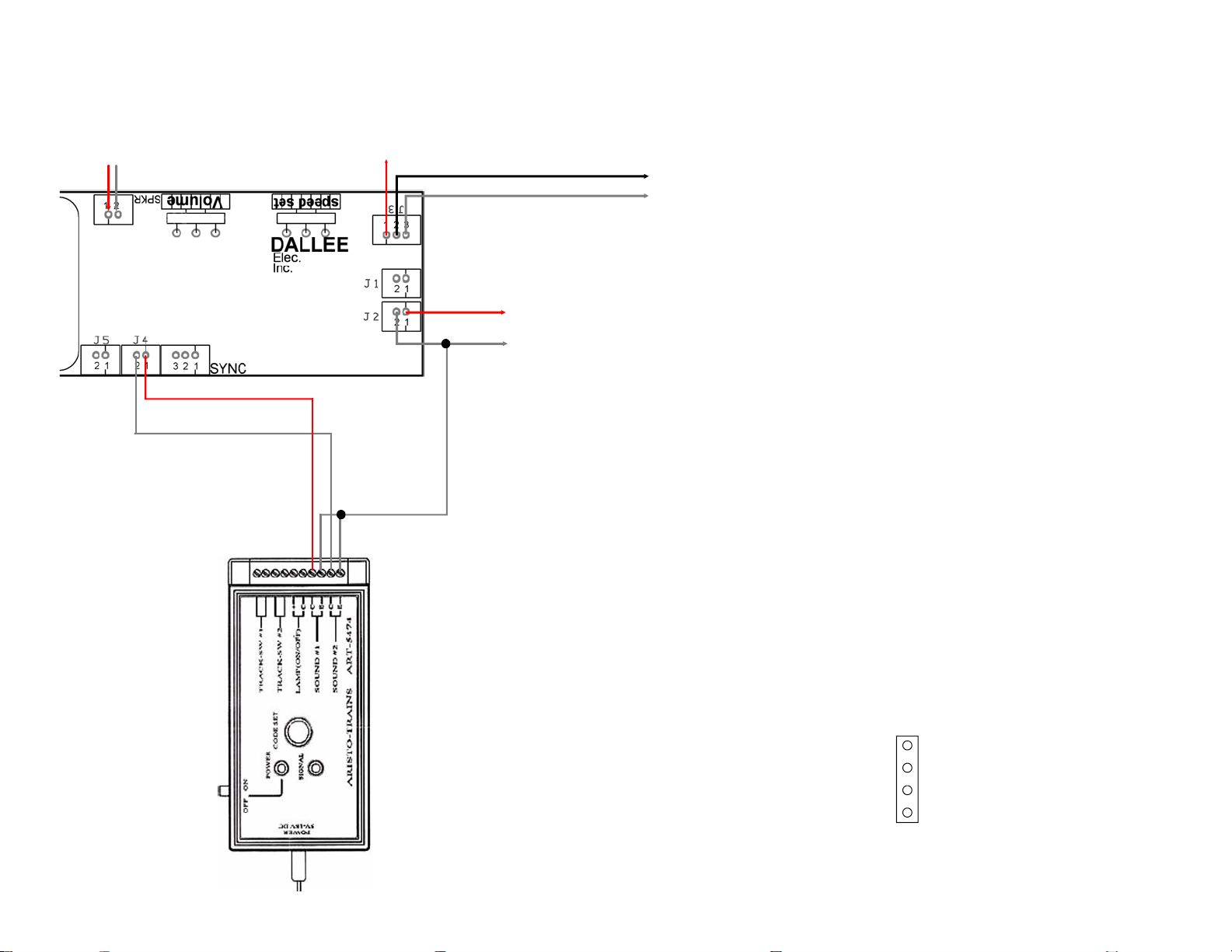
Aristocraft/Crest #CRE-57000 Revolution Receiver (2.4 GHz) installation.
J2: DC power input/output.
This is the rectified power from the sound system. When operating
on DC track power, since the polarity is unknown, the input power
must be connected to J1 input power.
The J2 power is an input for the sound system as well as a DC
power output when J1 is the input power. It can be used to power our
11 or 22 watt amplifier's (item 671, 672). The DC output is limited and
is not intended to operate other items.
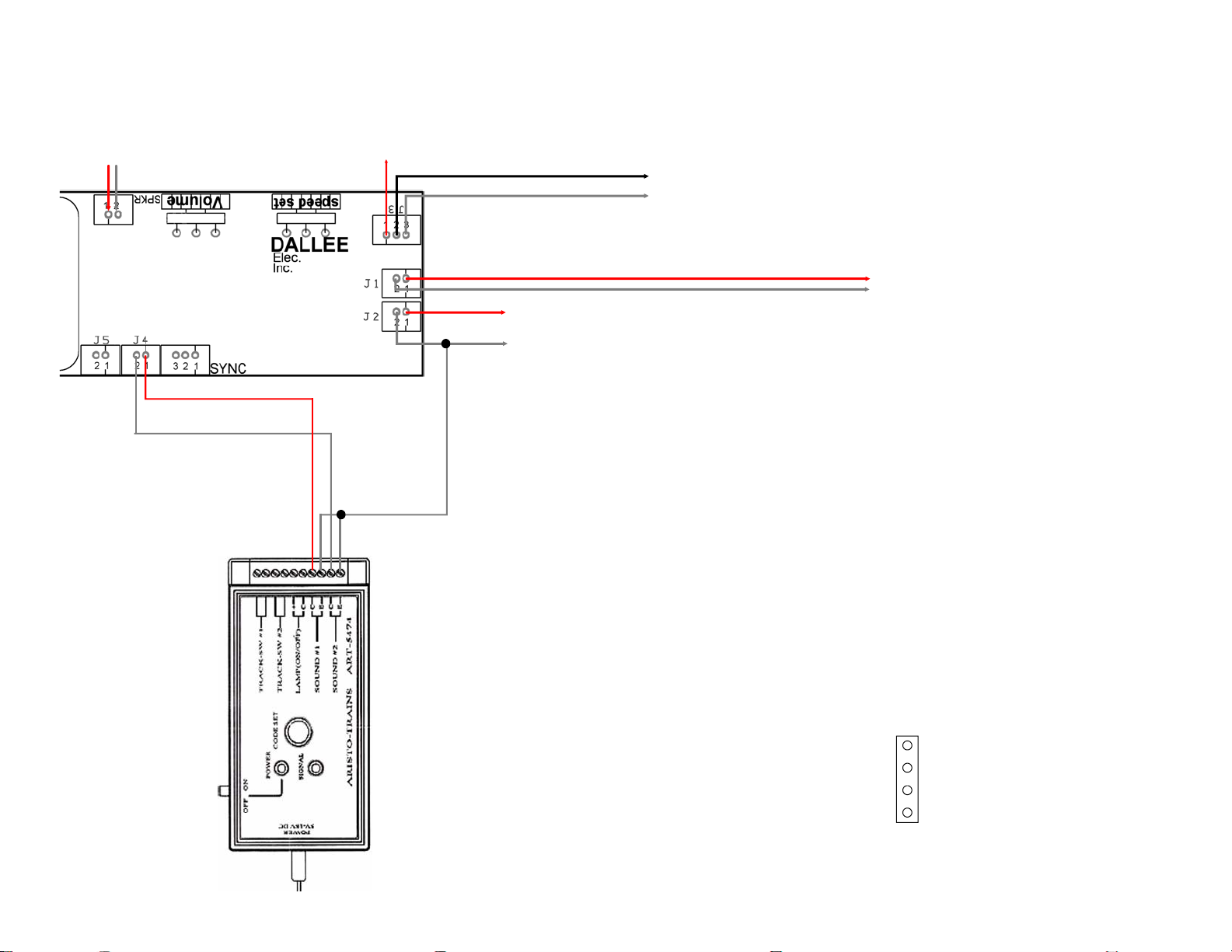
If you purchased the "Auto-Horn" or "Auto-Whistle" type sound units,
you will not have enough 2 pin connectors to utilize both J2 and J5.
Normally this is not a problem since J2 is normally not connected.
Extra wire harnesses can be purchased if needed.
J1: Track Input Power.
Input voltage of 7 to 24 volts DC or AC.Absolute
maximum input is 35 volts DC!
Connect to the track input from each truck, detailed
picture shown below for AristoCraft engines.
Remember that track powered units will not operate
properly until the track power is at least above 6 volts.
Amplifier's require a minimum of 12 volts DC to
operate!
Your receiver battery power may be the same power as
the sound system and amplifier (if present). If you have
a different battery for the receiver and sound system,
then you should connect the "-" of each battery system
together.
AristoCraft boards labeled "SOUND PWR" are actually connected to the "Motor Power" before the motor "On/Off"
switch. While they can be connected to this connector, it is not ideal since the motor switch does not disconnect this
connection when the motor power is switched off. Connect these two wires to either the motor power leads or the
"Sound Pwr" connector wires. This is the same that goes to the motor. The "Sound Power" should come from the
track or battery and not the motor in this application. See wiring example on lower part of this page.
Diesel sound: This connection tells the sound system what speed / RPM to operate the diesel's prime mover sound.
Steam sound: This connection tells the sound system what rate to operate the auto-chuff. If you are using the
"SYNC" input, don't connect anything to J3!
Red - no
connection
Red
Gray
Red
Gray
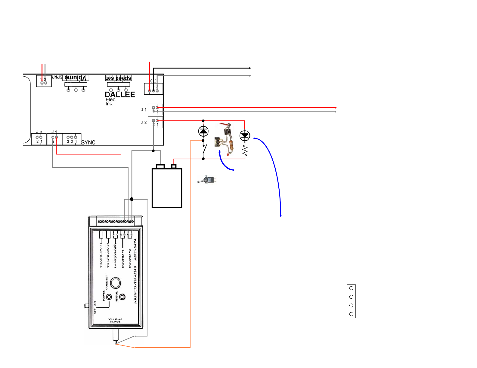
J1: "Sound Power" connection.
As shown, solder the red & gray wires to the center of the
"Battery / Track" power selector switch. This connects to J1
of the sound system and is the best selection to power the
sound unit since polarity is not important. This is also true
when operating the sound unit w/o a receiver as well.
Red & Gray
to J1
"SOUND PWR" connector is internally connected to the motor power before the Motor ON/OFF
switch. Therefore if you use the Red & Green wires from this and connect them to the J3 White &
Black wires, the sound unit will ramp up/down with speed setting changes w/o the motor running
when the MOTOR switch is set to the OFF position. To prevent this from
happening, solder the Black J3 wire as shown to the middle of the MOTOR
switch and the "SOUND PWR" Green wire to the White J3 wire (cut or tape
the Red "SOUND PWR" wire since it is not used). By doing so, when the
motor power switch is turned OFF the sound system will produce idle
sounds.
Remember, if this is a steam sound unit and you are intending to synchronize
the chuff sound, don't connect the J3 black & white wires to this board. They
get connected to the synchronization device and to the "SYNC" connector
and not J3! Only older software units require both J3 and the SYNC
connector to be used.
"SPK" : Speaker connector. Connect to Sound units "SPKR" connector wires.
If you did not purchase connectors, cut or splice the Red & Gray wires that connect to the
"SPKR" socket to the Red & Black wires from the main board. Either wire nut or solder
and tape / heat shrink tube the connection.
MOTOR
SWITCH
POWER
SELECTOR
SWITCH
ON
OFF
TRACK
BATTERY
Black
White
Standard DCv3 orAuto-Horn / Auto-Whistle Sound System
Mother Board w/o receiver:
Receiver "AUX-OUT"
connector
Extra function
"AUX-OUT" wires not
connected for sound
unit operation. Be
sure to tape ends to
prevent shorts!