DAMPP-CHASER Piano Life Saver System User manual

VERTICAL
5-PART SYSTEM INSTALLATION INSTRUCTIONS
TOOLS REQUIRED: Use either a #2 Phillips head driver or a 1/4-inch hexhead driver, as both types of screws are
included with this sysem. To install the system, you will need:
• racheting driver • screw starter •scissors
• cordless drill • small hammer •file
• small blade screwdriver • chalk or other marker •measuring tape
• wirecutters
The following is a list of components:
.Purpose
191 cm Dehumidifier (with attached extensions) Removes excess moisture from the piano
1Humidistat Controls the Humidifier and Dehumidifier
1Humidifier Brings moisture into the piano
1Water Sensor Probes Measure water depth in Humidifier
1Humidifier Heater Bar Warms pads to aid evaporation
1Two-light Panel Shows System is energized and when to add water
1Watering tube Enables the delivery of water to the Humidifier
1Humidifier pads Used to vaporize moisture from the Humidifier
13 m Extension Power Cord Connects Humidistat to electrical wall outlet
1 Moisture Distribution Baffle Dispenses moisture throughout the piano
1Watering Can For adding water to the Humidifier
1Bottle of Humidifier Treatment Additive that prolongs the life of the pads
1Hardware kit Described below
1System Care and Maintenance sheet / 5-Year Warranty Certificate
The hardware kit includes the following:
2 Y Hangers Used to suspend the Humidifier tank when necessary
13 13 mm #8 screws Mounts clamps
219 mm #8 screws Used to attach the light panel
3 5 mm clamps Attaches wire between light panel and Humidistat
213 mm standard clamps Attaches watering tube between keybed and Humidifier
2Half clamps and serrated washers Attaches the end of the watering tube to the rim
66 mm clamps Anchors Humidistat power cord wire
2Screw hooks Used to suspend the Humidifier when necessary. Used with Y Hangers
2Wire ties and cable ties Used to bundle excess cords
4Pin pegs Used to mount Dehumidifier and the Moisture Distribution Baffle
2 Plastic hanger C clips Used to mount the Humidistat on the Dehumidifier
1 “STOP, DO Not Unplug Label Can be attached to power cord near wall outlet
1Warranty Registration card
While we make every effort to ensure all components are included, it is a good idea to check that none are missing prior to
arriving at the installation location. In the unlikely event that a part is missing, please call your supplier with information from
the end of the box and the assembler’s name. The replacement part will be shipped to you without delay.
Smart Bracket package includes:
Smart Bracket Sensors Attaches to Humidifier heater bar and senses when pads are dry
Single-Light Cube Signals when Humidifier pads are dry

2
DAMPP-CHASER CORPORATION
800-438-1524 • 828-692-8271 • Fax: 828-692-8272
www.PianoLifeSaver.com • e-mail: piano@dampp-chaser.com
Post Office Box 1610 • Hendersonville, North Carolina 28793 USA
To the Piano Technician Installer
CAUTION
You are responsible for making a proper System installation by carefully following these
instructions.
PLEASE PAY STRICT ATTENTION TO THE FOLLOWING ISSUES:
1) The vertical piano can be exposed to excessive condensation from the Humidifier if the baffle is
not installed.
2) If a cord/wire in the System is installed in direct contact with a Dehumidifier heating rod, over
time, the cord/wire could dry out and crack, posing a fire or shock hazard. Carefully anchor cords/
wires away from the Dehumidifiers with the ties and clamps provided with the System.
3) Do not use a Dehumidifier in the action of the piano without a Humidistat to control it. To
dehumidify the action, we recommend you install a 91 cm, 25-watt Dehumidifier outside the case,
under the keybed, and plug this Dehumidifier into the System’s Humidistat.
4) Advise your clients that they should use only Dampp-Chaser PAD Treatment in the Humidifier.
Other brands of water treatment may contain acids which can corrode strings and metal parts in
the piano. Use of another brand of treatment voids the System’s warranty and may also void the
piano manufacturer’s warranty.
OTHER IMPORTANT INFORMATION
1) The newly-installed Piano Life Saver System will alter the piano’s wood-moisture content and,
therefore, alter the tuning. Ideally, the System should be installed 3 weeks BEFORE the piano is
tuned.
2) A frayed or cracked electrical cord/wire can cause a fire or shock. If the piano runs over the
power cord it can be damaged. Inspect the System’s cords/wires each time you service the piano.
3) Installation of the Piano Life Saver System must be made by a professional Piano Technician or
Tuner. Any warranties stated or otherwise implied are void if the installation is made by someone
other than a professional Piano Technician or Tuner.
WW
WW
Warranty Service Call Parranty Service Call P
arranty Service Call Parranty Service Call P
arranty Service Call Policy:olicy:
olicy:olicy:
olicy: The 5-Year Warranty for this System covers parts only. Dampp-
Chaser Corp. assumes no responsibility for piano technician labor in maintenance, repair or
warranty service calls related to the Piano Life Saver System. When Systems are priced according
to the manufacturer’s guidelines, most installers agree there is sufficient compensation to cover a
possible warranty service call. At the time you install the System, please explain any
post-installation fees to the System owner.
Representative for all European countries:
Odd Aanstad
Boda Asen, SE-671 95 Klässbol, Schweden
Tel.: 0046 5705 1184, Fax: 0046 5705 1194 • e-mail: europe@dampp-chaser.com

3
STEP 1. HUMIDIFIER INSTALLATION
You should install the Humidifier first. When you unpack the
System box, you will find several items in the Humidifier tank:
Humidifier pads, the two-light panel, and the watering tube.
Remove the light panel and pads for later use. Uncoil the
watering tube and leave it outside the tank. Make sure the end of
the tube is within the plastic liner inside the tank. Please note the
Water Sensor probes and Humidifier heater bar are attached to
the Humidifier at the factory. The Water Sensor probes are
attached to the Humidifier heater bar mounting bracket at the
middle of the Humidifier (Figure 1).
The Humidifier pads are designed to wick water over the heater
bar, producing warm moist air currents which rise and are cir-
culated throughout the piano. The Smart Bracket sensors
(Figure 2) will signal via a red light when the pads no longer
wick water and require replacement. The Smart Bracket also
turns off the Humidifier heater bar when the pads fail or when the
Humidifier runs out of water.
Mounting the Smart Bracket: You will mount the Smart
Bracket outside the Clean Sleeve©on the Humidifier Heater Bar
(Figure 2). The Sleeve protects the Heater Bar from corrosion
caused by excessive minerals in the water.
Open the SB package and take out the SB sensors (with
attached C clips) and the red SB single-light cube. Put aside the
light for later. To attach the sensors to the heater bar, slide the
C clips on the SB sensors into the positions shown in Figure 2
and press firmly downward. The sensors on the Smart Bracket
should lie on the top of the heater bar.
Drape the Humidifier pads across the heater bar and push them
down into the tank as shown in Figure 1. If necessary, adjust
the C clips on the SB sensors to insure the pads are in direct
contact with the sensors. Unbundle the cords from the SB, the
Water Sensor probes and the Humidifier heater bar.
Remove the bottom panel of the piano and put the Humidifier
tank on the floor in the bottom corner of the treble or bass end
(Figure 3). Place the tank in the side where the trapwork does
not interfere.
FIGURE 1
Humidifier with
pads installed
FIGURE 3
Humidifier placement
Water sensor
probes
attached
to middle
mounting
brackets
FIGURE 2
PP
PP
PADAD
ADAD
AD PP
PP
PADAD
ADAD
AD
Smart Bracket
Heater Bar
NOTE: If the Smart Bracket is not mounted
OUTSIDE the Sleeve, the red “Pads” light
(on the light panel) will blink constantly.
Always mount the
Smart Bracket
probes outside the
plastic Sleeve.

4
STEP 1-A. SUSPENDING THE HUMIDIFIER TANK
ABOVE TRAPWORK
In some pianos, the trapwork prevents placing the Humidifier
tank in the bottom, and you will need to suspend the tank
above the trapwork (Figure 4).
When the position of the tank has been determined, center the
Moisture Distribution Baffle over the tank position. Then, mount
the Baffle according to the instructions in STEP 2.
Y hangers and screw hooks are used to suspend the tank
(Figure 5). First, attach the Y hangers to the inside of the tank
using the screws at the four corners of the tank. Loosen the
screws which are already on the tank. These screws do not
require wing nuts to secure them because they are self-locking
and will not loosen. If necessary, enlarge the holes in the liner
to drive the screws in.
Screw the hooks through the Baffle about 35 cm apart.Hang the
Humidifier as low as possible above the trapwork. To achieve
the proper height for the tank, it may be necessary to cut the Y
hangers’ top legs with your wire cutters. Note that the Dehu-
midifier will be installed approximately 20 cm above
the Humidifier.
STEP 2. MOISTURE DISTRIBUTION BAFFLE
INSTALLATION
Now, with the Humidifier in place you can install the Moisture
Distribution Baffle. Attach the baffle under the keybed so that it
is centered directly above the Humidifier tank. You may need to
use your scissors to make one or more cutouts in the baffle to
ensure that it clears any plate struts above it. You will need two
pin pegs (Figure 6) from the hardware kit. Push them through
the baffle and into the keybed about 15 cm from either end of
the baffle (Figure 7). A small hammer can be used to set the
pin pegs. On metal keybeds, use the Velcro to attach the baffle
(see below).
Properly installed, the baffle should not touch the strings nor
should it protrude above the bottom panel of the piano. The
crease should be up like a roof ridge to distribute the moist air
(Figure 8).
FIGURE 6
Pin Peg
FIGURE 8
Side view of installed baffle
BAFFLE
TANK
FIGURE 5
Attaching Y brackets
to the Tank
ß
Screw
hooks Y bracket
goes inside
tank and is
anchored by
screws
ß
FIGURE 4
Suspended Humidifier tank
FIGURE 7
Baffle affixed to keybed
with pin pegs
Pianos with
metal keybeds
Attach the baffle using the
Velcro on each end. Peel
off the clear covering and
press to keybed.

5
STEP 3. DEHUMIDIFIER INSTALLATION
First, hold the Dehumidifier inside the piano approximately
where you think it might need to go, to be sure it clears rods
and the plate without touching them. Press the pedals to be
sure they don’t touch the Dehumidifier when activated. You may
need to position the tank differently to avoid this problem.
To determine the height of the Dehumidifier, measure 35 cm
from the floor on the treble end and use chalk to mark a line from
front to back on the side of the piano (Figure 9). You will need
two pin pegs. Push a pin peg into the chalk line directly above
the Humidifier heater bar (this will allow the Dehumidifier to be
installed where it is centered over the tank). Measure 35 cm
from the floor of bass end and mount the second pin peg.
Notice that each end of the Dehumidifier extends almost
35 cm. Loosen the two clamp screws that secure the telescop-
ing ends. Notice the holes in the center of the caps at each end
of the rod. Pull out the extension (opposite the end with the
cord) 25 cm and tighten the screw. Put the pin peg at the treble
end into this hole (Figure 10). Now pull out the extension with
the cord and install it on the pin peg at the bass end. This
allows you to hang the rod. Tighten the extension screw loosely
but enough to hold the Dehumidifier in place. Step back and
look at the Dehumidifier to make sure that it is level and cen-
tered over the Humidifier tank and adjust if necessary. Now
tighten the screw to hold the Dehumidifier firmly in place. (Over-
tightening this small extension screw may cause stripping of the
threads.)
Note, that with either a tank resting on the floor or a suspended
tank (Step 1-A, page 4), the Dehumidifier should be located
approximately 20 cm above the Humidifier tank. (See the
Humidistat installation instructions below.) If you need to
protect the action from high humidity, mount a 91 cm, 25-watt
Dehumidifier under the keybed and control it with the Humidis-
tat. Be sure the Dehumidifier is mounted under the keybed in a
position that does not interfere with the removal of the bottom
board. Do not place a Dehumidifier in the action.
STEP 4. HUMIDISTAT INSTALLATION
With the Dehumidifier in place, you can now install the Humidi-
stat. It should be noted that the two end vent holes on the top of
the Humidistat act as a “chimney” to vent heat from the Humi-
distat. The holes should not be obstructed in any way in the
final installation. Later in the installation, the Water Sensor
probes, the Smart Bracket and the Light Panels will be plugged
into jack outlets at the bottom of the Humidistat. The Dehumidi-
fier and Humidifier will also be plugged into the Humidistat.
To install the Humidistat, find two C clip Humidistat hangers
(Figure 11). Attach the clips to the top of the Humidistat
by inserting the rectangular base of the clips into the rec-
tangular holes on either side of the 4 vent slots. Rotate the
clips 1/4 turn. You will feel the clips lock into place (Figure 12).
Now you are ready to snap the clips onto the Dehumidifier.
Carefully squeeze the clips onto the Dehumidifier until they
click into place (Figure 13).
FIGURE 12
Installing clips
onto Humidistat
FIGURE 13
Clipping Humidistat
to Dehumidifier
FIGURE 9
Installing Dehumidifier
35 cm from the floor of the piano FIGURE 11
FIGURE 10

Ideally, the lower corner of the Humidistat should be positioned
5 cm above the top of the Humidifier tank and 5 cm away from
the side of the Humidifier tank (Figure 14). With a suspended
tank, the Humidistat should also be positioned approximately
5 cm above and 5 cm from the side of the tank.
Now, plug the Dehumidifier and the Humidifier into the Humi-
distat. Make sure you do not put the plugs into the wrong
outlets. Connect the separate 3 m extension power cord to the
Humidistat outlet which is below the DEHUMIDIFIER outlet.
Then, route this Humidistat power cord out of the piano. First
run the 3 m cord to the treble end. Then run it up beside the
action and out the lid (Figure 15). From there the cord goes
down to an electrical outlet. With experience you will develop
your own technique for bringing the cord out under the lid. The
6 mm clamps may be used to attach the cord to the inside of
the piano.
You may prefer another method of running the power cord out
of the piano. If you feel comfortable drilling a hole in the
bottom board, you can bring the power cord out through the
hole (Figure 16). To provide strain relief for the cord, knot it
and secure the knot to an appropriate wood area with one of
the 6 mm clamps provided.
From the Humidifier tank, take the white cord, with the tele-
phone jack adaptor, and plug it into the Humidistat outlet
marked WATER SENSOR (Figure 17). Plug the Smart
Bracket’s phono jack adaptor into the outlet marked
SB/PADS. Using wire ties and cable ties, neatly rebundle
excess cords for the Dehumidifier, Humidifier, Water Sensor
and Smart Bracket.
FIGURE 14
Typical
Humidistat position
6
FIGURE 16
Alternate method for running
power cord out of piano
FIGURE 15
Routing the power cord
out of the piano
Dehumidifier
Humidifier
Heater
Bar
FIGURE 17
Power cord to
electrical outlet

STEP 6. WATERING TUBE INSTALLATION
The next step is to run the watering tube to the appropriate
location. You must be sure the tube will fit over the top of the
bottom panel. If the bottom panel pinches the tubing, check to
see if there is more space toward the middle of the panel. If it
does not fit, use your file to remove enough of the panel corner
to allow the tube to go through.
Two types of clamps are provided to anchor the watering tube:
(2)13 mm standard clamps and (2) 13 mm half clamps (Figure
20). Use 13 mm screws to mount the half clamps and 13 mm
screws for the standard clamps.
Figure 21 shows a typical watering tube installation. It’s
important to curve the tube so it can be pulled out freely for
watering. To make this possible, the open side of the half
clamps should face the front of the piano. Serrated washers bite
into the wood and keep the half clamps in the proper position.
The end of the watering tube should extend beyond the first half
clamp by 3 cm to 5 cm. Position the standard clamps to prevent
sagging of the tube in locations that do not interfere with
replacement of the bottom panel.
After the Piano Life Saver System is completely installed,
plug the Humidistat into a non-switchable wall outlet where
it cannot be turned off and therefore will be fully energized at
all times.
FIGURE 18
Tongue-latch and prongs
insert in openings
FIGURE 19
Placement of Light Panel
FIGURE 20
Two types of clamps for Watering Tube
(A) standard clamp
(B) half clamp
FIGURE 21
Placement of Watering Tube clamps
AB
half clamp
half clamp
standard clamps
STEP 5. LIGHT PANEL INSTALLATION
The two-light panel (Figure 18) features a green light marked
POWER, to indicate the System has electrical power, and a
yellow light marked WATER, which blinks when the Humidifier
needs water. There will be a single-light cube with a red light for
the Smart Bracket. The red light, marked PADS, will blink when
the pads need to be replaced. Connect the two-light panel and
single-light cube together (Figure 18) by inserting the tongue-
latch and two prongs (on the side of the single-light cube) into
the corresponding openings on the two-light panel. Insert the
metal prongs first while firmly pushing the panels together.
NOTE: the tongue-latch is slightly bent to create a snug fit
between the two panels.
To mount the light panel select (2) 19 mm screws and (3)
5 mm clamps with (2) 13 mm screws. Now, run the light panel
cord so that the panel is at an appropriate location under the
keybed. Usually this is at the extreme treble end beside the leg
of the piano. Use the two 19 mm screws to attach the light
panel under the keybed (Figure 19). Take the phone jack
adaptor from the light-panel and plug it into the Humidistat
outlet marked LIGHTS.
Be sure none of the cords/wires touch the Dehumidifier
rods, as exposure to heat can damage the cords/wires.
Conceal the cords/wires from the light panel using the 5 mm
clamps and a wire tie, if necessary.
Two-light
panel
SB
light
7

8PN 20393-E. 1/10
STEP 7. WATERING THE SYSTEM
The final step is to fill the Humidifier with water. FILL THE
HUMIDIFIER WITH THE WATERING CAN FILLED TO THE FULL
CAN MARK. Instruct the piano owner to add a watering can
filled to the full can mark whenever the yellow low water
warning light blinks. Also instruct the piano owner to add one
capful of PAD Treatment to each full watering can. PAD Treat-
ment inhibits mildew in both the watering tube and the Humidi-
fier tank and increases the life of Humidifier pads.
Warning: Add only Dampp-Chaser PAD Treatment to the
Humidifier water. Other brands of water treatment may
contain acids which may corrode strings and metal parts in
the piano. The use of other water treatment preparations will
void the warranty of the Piano Life Saver System and may
void the warranty of the piano manufacturer.
If tap water comes from a well or is “hard” water, meaning
containing significant minerals, we recommend using distilled
water. If distilled water is used, add PAD Treatment (according
to the label instructions) to insure there are adequate electro-
lytes in the Humidifier to support operation of the low water
warning light. Without sufficient electrolytes, the light will blink
continuously, even when the tank is full. Do not put salt in the
Humidifier, as it is corrosive.
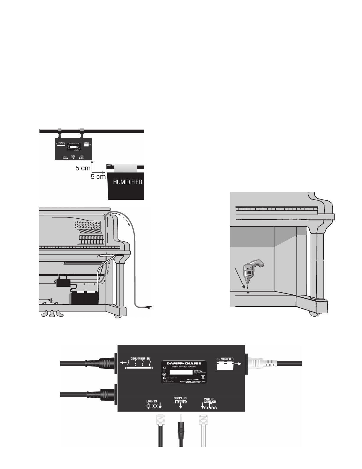
To fill the Humidifier tank, simply reach under the keybed, pull
the tubing out of the half clamps, connect the spout inside the
tube, raise the watering can, and add water. After the humidifier
is filled, the watering can (which is still connected to the
watering tube) should be lowered below the bottom of the rim
so that any water remaining in the tube is drained into the
watering can. Then, disconnect the watering can from the tube
and push the tube back into the half clamps. The System is
designed so siphoning will not occur. This completes the
installation of the System.
Humidifier Maintenance: To ensure a properly functioning
Humidifier, the pads should be changed at least twice each
year. This applies whether a Smart Bracket is used or not.
Change them during the fall service of the piano and then again
in the spring. Replacement pads can be obtained from Dampp-
Chaser or from any Dampp-Chaser distributor. Clean the
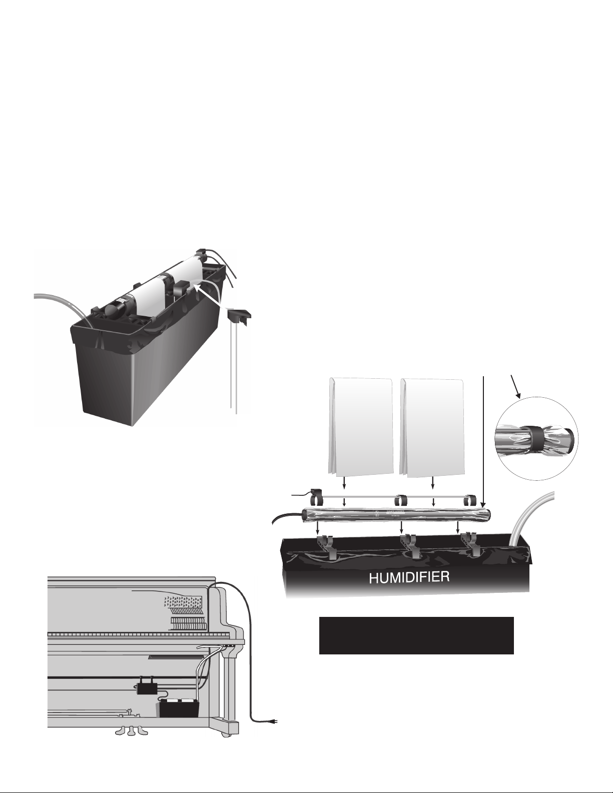
Humidifier once yearly by changing the liner. Be sure that the
watering tube is inside the liner when it is replaced. The Tank
must be lowered to do this. The holes in the new liner may be
enlarged with a pair of scissors to make installation easier.
When you replace the liner, also replace the plastic Clean
Sleeve on the Humidifier Heater Bar to protect the Bar from
excessive corrosive minerals in the water (Figure 2, page 3).
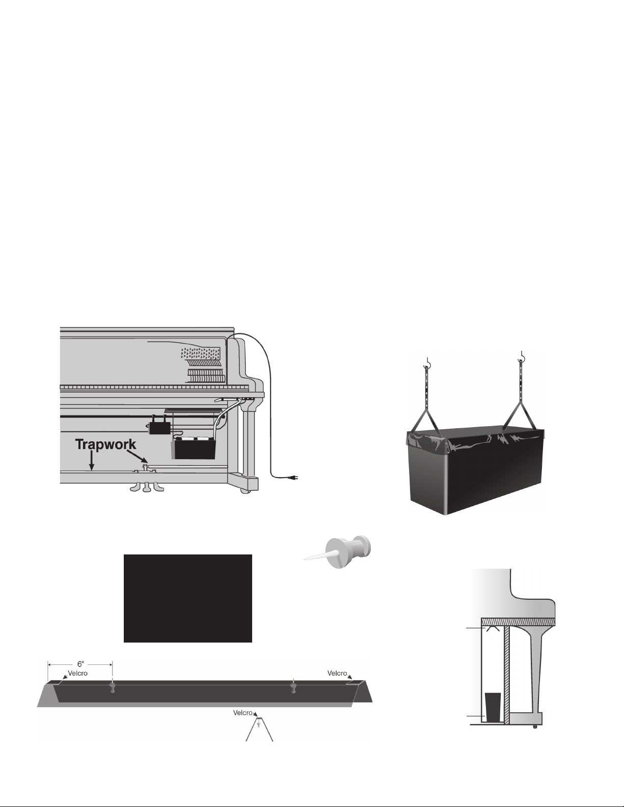
Smart Bracket Maintenance: If the System includes the
optional Smart Bracket, the sensor wires operate more effec-
tively if the wires are kept free from corrosion and minerals.
During pad changing, remove the Bracket from the heater bar.
Remove the mineral residue on the wires by scraping with the
dull edge of a knife held perpendicular to the wire. Alternatively,
it may be simpler to bring a new SB to replace the old one.
Replacement SB’s are available from your Dampp-Chaser
distributor. Be sure to mount theSB outside the Sleeve on the
Humidifier Heater Bar.
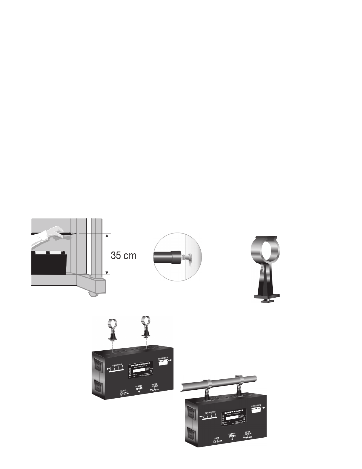
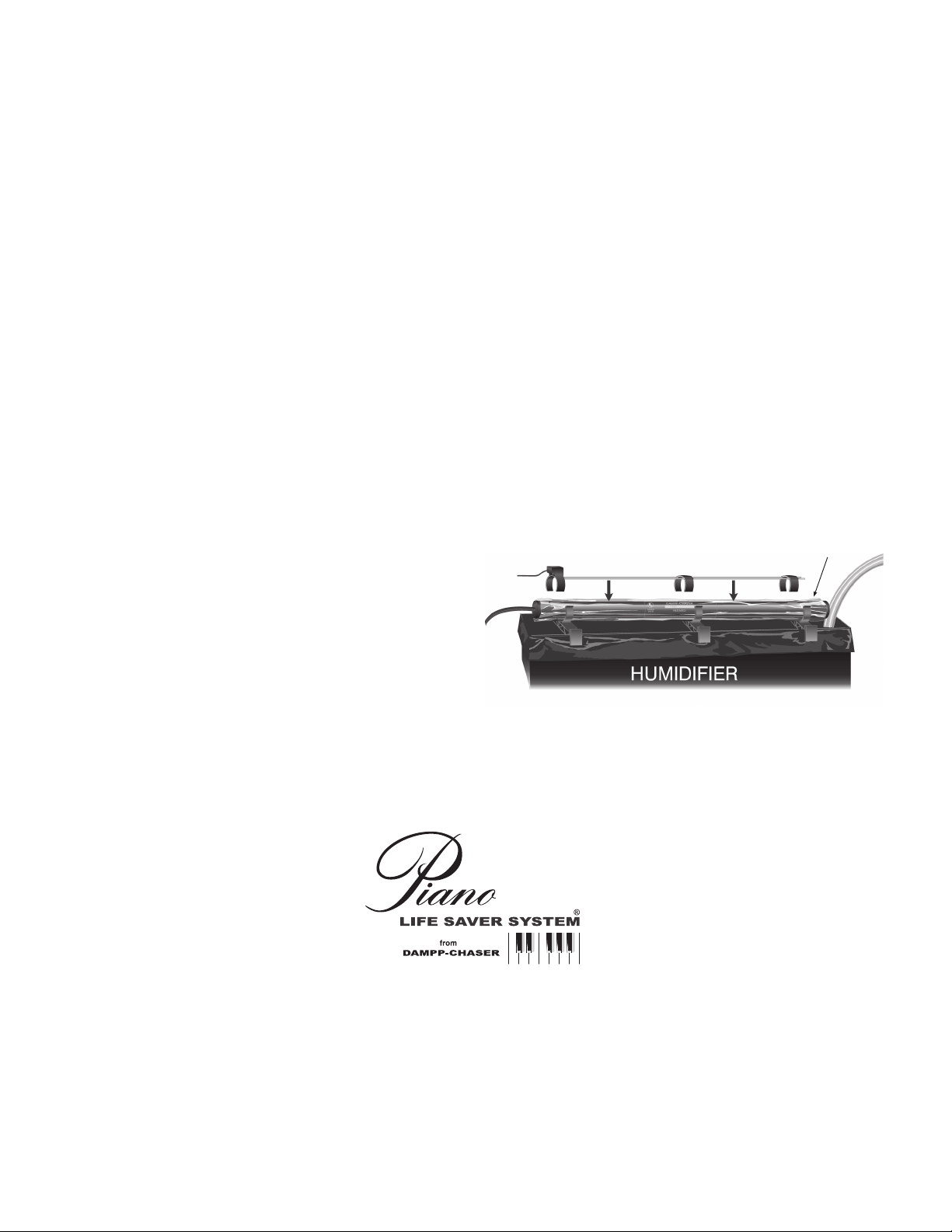
To protect the Humidifier Heater Bar from corrosion due to
excessive minerals in the water, when you service the
Humidifier, put a plastic Clean Sleeve®on the Heater Bar.
CONTACT YOUR DISTRIBUTOR OR PARTS SUPPLIER WITH
QUESTIONS ABOUT THE SYSTEM.
Technical Representative for all European countries:
Odd Aanstad
Boda Asen, SE-671 95 Klässbol, Schweden
Tel.: 0046 5705 1184, Fax: 0046 5705 1194 • e-mail: europe@dampp-chaser.com
DAMPP-CHASER CORPORATION
Post Office Box 1610
Hendersonville, North Carolina 28793 USA
828-692-8271 • Fax: 828-692-8272 •e-mail: piano@dampp-chaser.com
www.PianoLifeSaver.com
Clean Sleeve®
Always mount the Smart Bracket
OUTSIDE the plastic sleeve
FIGURE 22
Table of contents
Other DAMPP-CHASER Musical Instrument manuals