A comprehensive range of product
Product basics
The K4000 is a high frequency inverter designed for application up to 4000 Hz. The
K4000 family consists of several models with output ratings from 5 to 120 kVA. the
selective harmonic suppression -SHS - developed by DANAHER-MOTION, is aimed
at reducing motor losses and winding stresses without output filter.
• The KEYPAD PC560 control unit can be integrated on the front panel or supplied
as a separate remote control unit.
• The drive is equipped with a RS232 / 422 serial link. A communication protocol in
terminal mode for PC is available on request
• The UL certification of the KT4000 is in process
• The 19” rack version KL4000 will not be UL certified
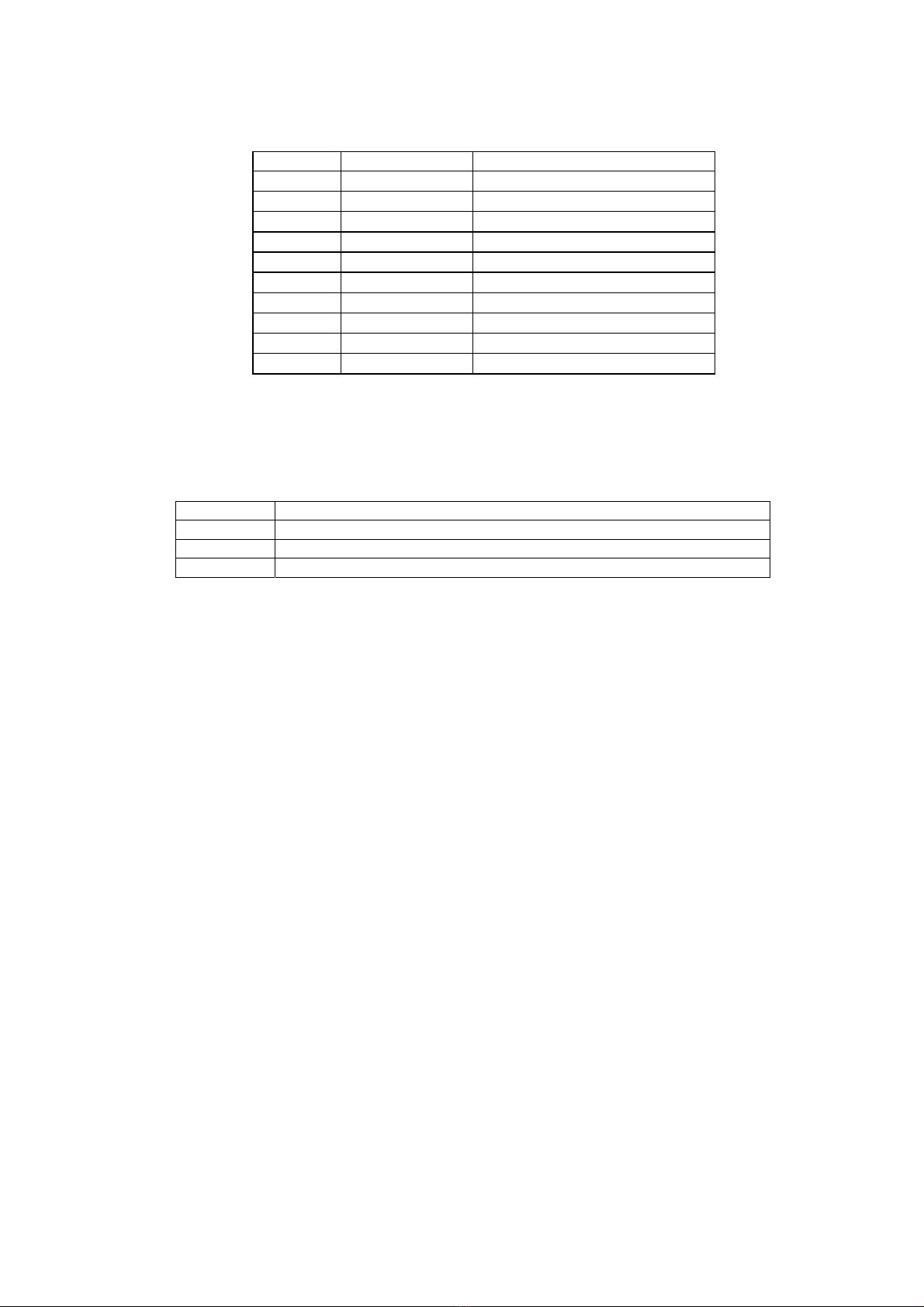
Main technical data
• Input voltage, all units, 3 x 200 V to 3 x 480 V auto-ranging, no line transformer
• Output voltage VRMS : 0 … UIN, max. 3 x 460 V
• Output frequency range 0 … 4000 Hz
• Ambient temperature 40°C
• Continuous current overload 120% without time limitation
• Max current overload 150% for 1 min / every 10 min
• Short-circuit protection: suitable for use on a circuit capable of delivery not more
than 5000 ARMS symmetrical Amperes, 480 V maximum.
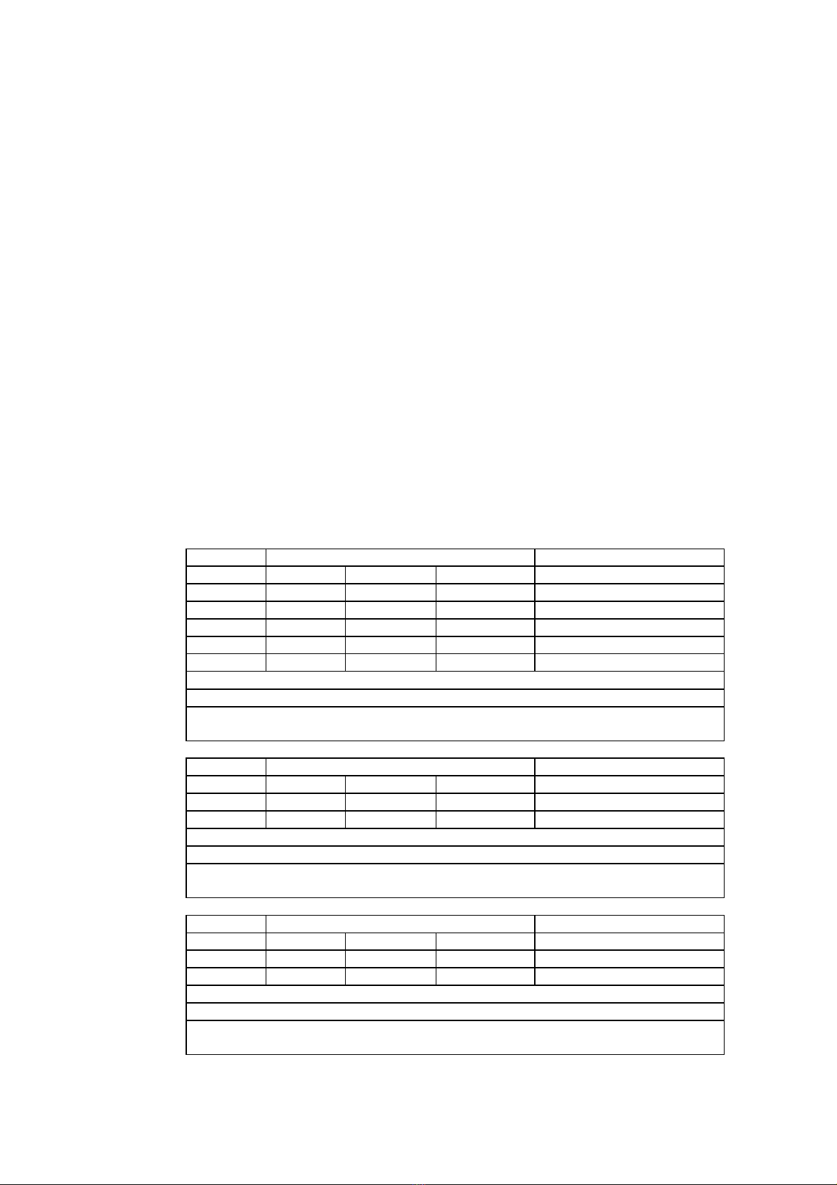
Current and Power ratings
Model Output Current ARMS Typical motor power
Nominal Continuous Peak kW @ 3 x 400 V
KT4005 5 6 10 2.5
KT4010 10 12 15 5
KT4015 15 18 23 7.5
KT4020 20 24 30 10
KT4030 30 36 45 15
Input current: All units are rated for a maximal input current of 32 ARMS
Input terminals: 10 mm2
Input cables: Minimum section 6 mm2resp. 10 AWG
Use copper conductors 75°C only
Model Output Current ARMS Typical motor power
Nominal Continuous Peak kW @ 3 x 400 V
KT4040 40 50 60 20
KT4060 60 75 90 30
Input current: All units are rated for a maximal input current of 63 ARMS
Input terminals: 35 mm2
Input cables: Minimum section 25 mm2resp. AWG 4
Use copper conductors 75°C only
Model Output Current ARMS Typical motor power
Nominal Continuous Peak kW @ 3 x 400 V
KT4090 90 110 135 45
KT4120 120 145 180 60
Input current: All units are rated for a maximal input current of 160 ARMS
Input terminals: 70 mm2
Input cables: Minimum section 50 mm2resp. AWG 1
Use copper conductors 75°C only
S476-gb-0348 User Manual K4000 Page 7 / 48