2
Contents
1
BACKGROUND ............................................................................................................................................................ 4
1.1
W
HAT IS A TELEPHONE HYBRID
?.................................................................................................................................. 4
2
GENERAL DESCRIPTION ........................................................................................................................................... 5
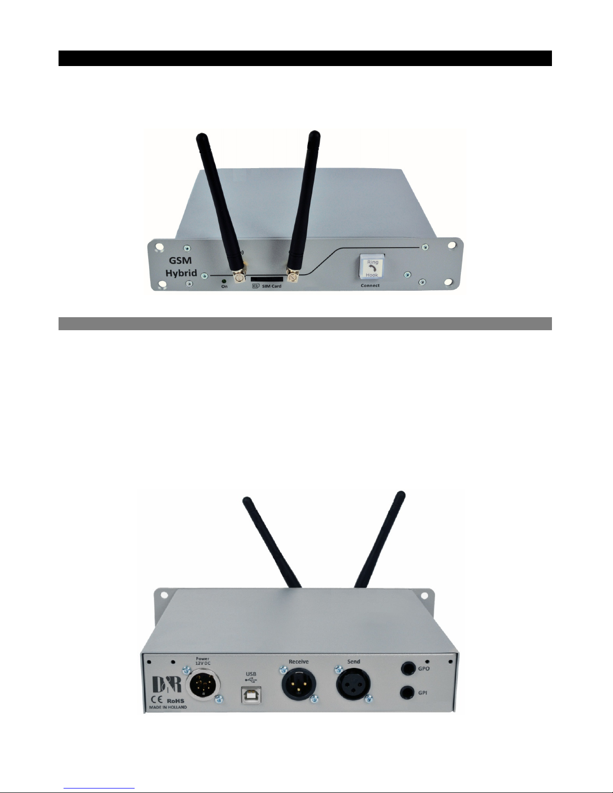
2.1
F
RONT PANEL
........................................................................................................................................................... 5
2.2
R
EAR PANEL
............................................................................................................................................................. 5
2.3
I
NPUTS AND
O
UTPUTS
................................................................................................................................................ 6
3
SOFTWARE .................................................................................................................................................................. 7
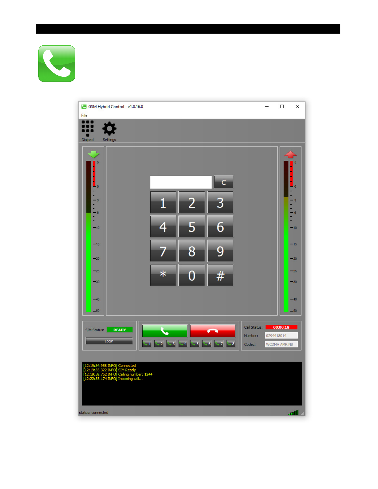
3.1
I
NSTALLATION
.......................................................................................................................................................... 8
3.2
F
EATURES
.............................................................................................................................................................. 12
3.3
S
ETTINGS
............................................................................................................................................................... 15
4
GETTING STARTED .................................................................................................................................................. 16
4.1
H
ARDWARE
S
ETUP
.................................................................................................................................................. 16
4.2
M
AKING CALLS
....................................................................................................................................................... 17
4.3
R
ECEIVING CALLS
.................................................................................................................................................... 17
5
SPECIFICATIONS ...................................................................................................................................................... 18
5.1
A
UDIO
I
NPUT
(SEND).............................................................................................................................................. 18
5.2
A
UDIO
O
UTPUT
(RECEIVE)..................................................................................................................................... 18
5.3
G
ENERAL
............................................................................................................................................................... 18
6
DIMENSIONS ............................................................................................................................................................. 19
7
SUMMARY ................................................................................................................................................................. 19
8
ELECTROMAGNETIC COMPATIBILITY ................................................................................................................ 20
9
DECLARATION OF CONFORMITY.......................................................................................................................... 20
10
PRODUCT SAFETY ................................................................................................................................................ 21
11
CAUTION................................................................................................................................................................ 21