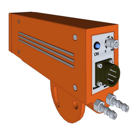
Danieli Automation ID6100 User manual

AUTOMATION
ID6100
Manuale d’installazione ed uso
Instruction Manual
Manual de instalación y uso
Manuel d'instruction et d'utilisation
Installations und Bedienungsanleitung
Manual de instalação e uso
RILEVATORE D’ANSA AD INFRAROSSI
INFRARED LOOP DETECTOR
DETECTOR DE BUCLE CON INFRARROJOS
DÉTECTEUR À BOUCLE À INFRAROUGES
INFRAROT-SCHLINGENERMITTLER
DETECTOR DE LAÇO COM INFRAVERMELHOS

Pag. 3
Manuale d’installazione ed uso
IIttaalliiaannoo
Pag. 2
Danieli Automation - ID6100
IInnddiicceeddeeiiccoonntteennuuttii
1. Introduzione . . . . . . . . . . . . . . . . . . . . . . . . . . . . . . . . . . . . .4
2. Descrizione Generale . . . . . . . . . . . . . . . . . . . . . . . . . . . . . . . .4
2.1 Campi di applicazione . . . . . . . . . . . . . . . . . . . .4
2.2 Aspetto fisico . . . . . . . . . . . . . . . . . . . . . . . . . . .4
3. Caratteristiche tecniche . . . . . . . . . . . . . . . . . . . . . . . . . . . . . .5
4. Collegamenti fotocellula . . . . . . . . . . . . . . . . . . . . . . . . . . . . . .6
4.1 Connessioni elettriche . . . . . . . . . . . . . . . . . . . .6
4.2 Dispositivo di segnalazione . . . . . . . . . . . . . . . .6
4.3 Dispositivo di raffreddamento . . . . . . . . . . . . . . .6
5. Configurazione del fotorilevatore . . . . . . . . . . . . . . . . . . . . . . . .7
5.1 Impostazione uscita in tensione (POS) . . . . . . . .7
5.2 Impostazione uscita in corrente (IPO) . . . . . . . .7
5.3 Impostazione angolo visivo . . . . . . . . . . . . . . . . .7
5.4 Regolazione automatica della sensisbilità . . . . . .7
5.5 Impostazione modalità di lettura . . . . . . . . . . . .8
6. Installazione . . . . . . . . . . . . . . . . . . . . . . . . . . . . . . . . . . . . .9
6.1 Posizionamento . . . . . . . . . . . . . . . . . . . . . . . . .9
6.2 Protezione . . . . . . . . . . . . . . . . . . . . . . . . . . . .10
6.3 Raffreddamento . . . . . . . . . . . . . . . . . . . . . . . .10
7. Manutenzione . . . . . . . . . . . . . . . . . . . . . . . . . . . . . . . . . . . .11
7.1 Test di funzionamento . . . . . . . . . . . . . . . . . . .11
7.2 Controlli periodici . . . . . . . . . . . . . . . . . . . . . . .11
7.3 Ricerca guasti . . . . . . . . . . . . . . . . . . . . . . . . .11
8. Parti di ricambio . . . . . . . . . . . . . . . . . . . . . . . . . . . . . . . . . . .12
9. Informazioni aggiuntive . . . . . . . . . . . . . . . . . . . . . . . . . . . . . .13
Dimensioni . . . . . . . . . . . . . . . . . . . . . . . . . . . .13
Supporto . . . . . . . . . . . . . . . . . . . . . . . . . . . . .14
10. Assistenza tecnica . . . . . . . . . . . . . . . . . . . . . . . . . . . . . . . . . .14
Il materiale utilizzato per l’imballaggio di questo prodotto è al 100% riciclabile
The material used for packaging this product is 100% recyclable.
El material utilizado para el embalaje de este equipo es reciclable al 100%
Le matériel utilisé pour l'emballage de ce produit est 100% recyclable.
Das zur Verpackung dieses Produktes verwendete Material ist zu 100% recyclebar.
O material utilizado para a embalagem deste produto é 100% reciclável.
Questo prodotto è conforme alle direttive europee sulla sicurezza e compatibilità elettromagnetica.
This product complies with the European directives on safety and electromagnetic compatibility.
Este producto cumple con las directivas europeas sobre la seguridad y compatibilidad electroma-
gnética.
Ce produit est conforme aux directives européennes en matière de sécurité et de compatibilité élec-
tromagnétique
Dieses Produkt entspricht den europäischen Richtlinien zur Sicherheit und elektromagnetischen
Verträglichkeit
Este produto encontra-se em conformidade com as directivas européias de segurança e compatibi-
lidade electromagnética
(EMC directive
89/336/EEC;
Low voltage
directive
73/23/EEC).
IIDD66110000
RRIILLEEVVAATTOORREEDD’’AANNSSAAAADDIINNFFRRAARROOSSSSII
MMaannuuaalleedd’’iinnssttaallllaazziioonneeeedduussoo
Edizione: 1.0 Data: Sept.2004
Codice:DA-04-GE-MA-51.0
Copyright © Danieli Automation Spa

Pag. 5
Manuale d’installazione ed uso
IIttaalliiaannoo
Pag. 4
Danieli Automation - ID6100
Spettro rilevabile da 830 a 1000 nm
Temperatura dell'oggetto da rilevare da 700 a 1200 °C
Ampiezza del campo di osservazione verticale: 45°/30° (selezionabile)
orizzontale: 0,5°
Risoluzione della posizione 0,1°
Temperatura di lavoro da 0 a +50°C
Temperatura di immagazzinamento da -5 a +80°C
Alimentazione 24 V c.c. ± 20%
Consumo 300mA 24 Vc.c. 7.2W
Uscita NPN Collettore aperto, 30 V Max
I out Max = 200 mA (*)
@T amb = 50°C
una sola uscita utilizzata (**)
Uscita PNP Collettore aperto, 30 V Max
I out Max = 200 mA (*)
@T amb = 50°C
una sola uscita utilizzata (**)
Posizione d’ansa, uscita analogica 0/10V, -10/+10V, -5/+5V,
in tensione (POS) Imax=10mA (*) (selezionabile)
Posizione d’ansa, uscita analogica 0/20mA, 4/20mA, (selezionabile)
in corrente (IPO) R max 250 Ohm (*)
Tempo di risposta <3 ms
Alimentazione dispositivo di Auto-test 24 V c.c. / 10 mA
Grado di protezione IP55
Dimensioni (connettori esclusi) 266 x 180 x 64 mm (fig.13)
Peso 1.85 Kg
(*): Uscite protette contro i corti circuiti.
(**): Nel caso in cui vengano utilizzate con
temporaneamente entrambe le uscite (NPN
e PNP), la massima corrente consentita è
100 mA per ciascuna uscita.
Scopo di questo manuale è fornire le informazioni necessarie per l'installazione, l'utilizzo e la manu-
tenzione del rilevatore d'ansa ID6100.
Vengono fornite indicazioni sul principio di funzionamento, sul campo di applicabilità del dispositi-
vo, sulle parti di ricambio.
ID6100 è un rilevatore ottico ad infrarossi, funzionante con corpi caldi a temperatura superiore ai
700 °C .
É progettato per l'utilizzo in laminatoio, posto fra due gabbie, come sensore per il rilievo della posi-
zione d'ansa.
Il sistema ottico è composto da un filtro ed una lente asferica che focalizza l'emissione infrarosso del
laminato su un array lineare di fotoelementi (CCD).
22..11CCaammppiiddiiaapppplliiccaazziioonnee
ID6100 è progettata specificamente per l'impiego negli impianti di laminazione a caldo per l'acciaio.
Le caratteristiche costruttive del fotorilevatore lo rendono adatto all'utilizzo in ambienti industriali gra-
vosi.
ID6100 è predisposta per essere alimentata a corrente continua in bassa tensione, ed è provvista di
uscite analogiche (in tensione e in corrente) e uscite a collettore aperto NPN e PNP, isolate galvani-
camente, protette contro i sovraccarichi e le sovratensioni.
22..22AAssppeettttooffiissiiccoo
Il contenitore del fotorilevatore ID6100, come visibile in figura 1, è realizzato in pressofusione di allu-
minio ed è provvisto di un circuito incorporato per il raffreddamento a fluido.
Detto circuito può essere alimentato con aria, con acqua o con altri fluidi refrigeranti in funzione
delle condizioni ambientali di lavoro.
Il fotorilevatore è provvisto di una piastra di supporto di forma semicircolare che ne consente il fis-
saggio e l'orientamento sul piano verticale entro un angolo di circa 30°.
11..IINNTTRROODDUUZZIIOONNEE
22..DDEESSCCRRIIZZIIOONNEEGGEENNEERRAALLEE
33..CCAARRA
ATTTTEERRIISSTTIICCHHEETTEECCNNIICCHHEE
11

Pag. 7
Manuale d’installazione ed uso
IIttaalliiaannoo
Pag. 6
Danieli Automation - ID6100
ON
12345678
ON
12345678
44..CCOOLLLLEEGGAAMMEENNTTIIFFOOTTOOCCEELLLLUULLAA55..CCOONNFFIIGGUURRAAZZIIOONNEEDDEELLFFOOTTOORRIILLEEVVAATTOORREE
LMA
B
KUN
H
SR
D
E
F
G
CJ TVP
+24 Vdc
+24 Vdc
IPO
0V
POS
test
0V
0 Vdc0 Vdc
250 Ohm
max
PNP output
NPN output
A
F
C
K
L
P
J
Connector pins
U
Sul lato posteriore del fotorilevatore trovano posto i dispositivi di connessione e segnalazione.
44..11--CCoonnnneessssiioonniieelleettttrriicchhee
Fig. 3(1). Connettore a 19 contatti, tipo MIL
Le uscite analogiche sono galvanicamente isolate rispetto alle uscite digitali, e fanno riferimento
rispettivamente a 0V e 0VE.
22
2
3
1
44..33DDiissppoossiittiivvooddiirraaffffrreeddddaammeennttoo
Fig.3 (3) Attacchi da 1/4" GAS, per mandata e
scarico del circuito di raffreddamento a fluido
predisposto nel corpo del fotorilevatore.
22CCoonnnneettttoorreettiippooMMIILL
ccoonnccoolllleeggaammeennttii
eelleettttrriiccii,,uuttiilliizzzzaarree
ccaavvoosscchheerrmmaattooppeerr
iillccoolllleeggaammeennttooddeel
lllee
uusscciitteeaannaallooggiicchhee..
33VViissttaappoosstteerriioorreeddeellllaa
ffoottoocceelllluullaa,,ccoonn
ddiissppoossiittiivviiddii
ccoonnnneessssiioonneeee
sseeggnnaal
laazziioonnee..
44PPoossiizziioonnaammeennttooddeeiiDDIIPP--SSWWIITTCCHHaallll’’iinntteerrnnooddeell
ffoottoorriilleevvaattoorreeIIDD66110000
33
LED presenza
materiale
Connettore MIL
maschio 19 Poli DIP-SWITCH A DIP-SWITCH B
Connessioni
circuito di
raffreddamento
É possibile configurare le seguenti funzioni:
Range delle uscite analogiche in tensione e
corrente (POS e IPO)
Angolo verticale del campo visivo
(45° o 30°)
Regolazione automatica della sensibilità.
Modalitá di lettura barra singola / multipla.
La configurazione si effettua per mezzo di dip-
switch posti all'interno del fotorilevatore, ai quali
si accede rimuovendo il coperchio laterale.
Sono presenti due banchi di DIP-SWITCH, con-
trassegnati con A e B (figura 4).
55..11IImmppoossttaazziioonneeuusscciittaaiinntteennssiioonnee((PPOOSS))
La tabella seguente descrive come impostare i
DIP-SWITCH Banco A, per la selezione del
range dell'uscita POS (Tensione).
RRaannggeeuusscciittaaSSwwiittcchh::11SSwwiittcchh::22SSwwiittcchh::77
0 ÷ +10V ON OFF OFF
+10 ÷ 0V ON OFF ON
-5 ÷ +5V ON ON OFF
+5 ÷ -5V ON ON ON
-10 ÷ +10V OFF ON OFF
+10 ÷ -10V OFF ON ON
55..22IImmppoossttaazziioonneeuusscciittaaiinnccoorrrreennttee((IIPPOO))
La tabella seguente descrive come impostare i
DIP-SWITCH Banco A, per la selezione del
range dell'uscita IPO (Corrente).
RRaannggeeuusscciittaaSSwwiittcchh::33SSwwiittcchh::44SSwwiittcchh::55SSwwiittcchh::77
4 ÷ 20mA ON OFF OFF OFF
20 ÷ 4mA ON OFF OFF ON
0 ÷ 20mA OFF ON ON OFF
20 ÷ 0mA OFF ON ON ON
NOTA: Le impostazioni di fabbrica sono 0÷10 V
per l'uscita in tensione, e 4÷20 mA per l'uscita
in corrente. Se il rilevatore è montato con la pia-
stra di supporto verso il basso, 0V (o 4 mA) cor-
risponde a presenza materiale nella posizione
inferiore, 10V (o 20 mA) corrisponde a materia-
le nella posizione superiore.
NOTA: in assenza di laminato, l’uscita digitale è disattivata
mentre l'uscita analogica assume il valore del fondo scala
superiore (100%), cioè come se la barra fosse presente, e
fosse localizzata in alto.
55..33IImmppoossttaazziioonneeaannggoolloovviissiivvoo
La tabella seguente descrive come impostare i
DIP-SWITCH Banco A, per la selezione dell'an-
golo visivo.
AAnnggoolloovviissiivvooSSwwiittcchh::88
30 gradi OFF
45 gradi ON
55..44RReeggoollaazziioonneeaauuttoommaattiiccaaddeellllaasseennssiibbiilliittàà
Se la funzione è disattivata (OFF), il periodo di
scansione del CCD (e quindi la velocitá di
aggiornamento dell'uscita analogica di posizio-
ne) è fisso. Se la funzione è abilitata (ON), il
periodo di scansione del sensore CCD viene
modificato automaticamente per adattarsi all'in-
tensitá dell'emissione rilevata (dipendente dalla
temperatura del materiale).
Vista del connettore
lato saldature
PPiinnSSeeggnnaalleeFFuunnzziioonnee
J +24VE 24 VCC Alimentazione
C 0VE 0 VCC Alimentazione
P PFA/ Presenza materiale (uscita NPN)
K PFA Presenza materiale (uscita PNP)
A POS Posizione ansa (uscita in tensione)
L IPO Posizione ansa (uscita in corrente)
U-F 0V 0 Volt riferimento per IPO e POS
E Test 0 Vcc Alimentazione test
G Test 24 Vcc Alimentazione test
44..22DDiissppoossiittiivvooddiisseeggnnaallaazziioonnee
Fig.3 (2) indicatore luminoso a LED di colore
verde che si accende per segnalare lo stato di
"presenza materiale".

Pag. 9
Manuale d’installazione ed uso
IIttaalliiaannoo
Pag. 8
Danieli Automation - ID6100
500
410 270
1230
820
540 810 45° 30°
1000
1500
La tabella seguente descrive l'impostazione del
DIP-SWITCH Banco A, relativo alla funzione
Regolazione automatica della sensibilità.
RReeggoollaazziioonneeaauuttoommaattiiccaaddeellllaasseennssiibbiilliittààSSwwiittcchh::66
Disattivata OFF
Attivata ON
55..55IImmppoossttaazziioonneemmooddaalliittààddiilleettttuurraa
L'uscita analogica del rilevatore ID6100 puó
essere alternativamente correlata alla posizione
dell'asse della barra (P1: punto medio fra i bordi
superiore e inferiore), oppure al suo limite supe-
riore P2, esempio in figura 5.
Nel primo caso (asse della barra) si ha il vantag-
gio che la posizione è indipendente dal diame-
tro della barra stessa.
Nel caso in cui si presentino contemporanea-
mente più barre, la seconda opzione indica la
posizione del limite superiore della barra posta
in alto, esempio in figura 6.
Tramite i DIP-SWITCH del Banco B, è possibile
selezionare se il segnale di uscita deve essere
correlato all'asse della barra oppure al suo limi-
te superiore.
MMooddaalliittààddiilleettttuurraaSSwwiittcchh::11
Asse della barra OFF
Limite superiore della barra ON
Se è selezionata la modalitá di lettura del limite
superiore, è possibile utilizzare il rilevatore
ID6100 come strumento di misura della posizio-
ne di un corpo caldo di larghezza indefinita,
esempio in figura 7.
Nota: Dopo aver impostato la configurazione, richiudere la
copertura, verificando il corretto posizionamento della
guarnizione che garantisce la tenuta ermetica.
P1
P2
P1
P2
88CCaammppooddiirriilleevvaammeennttoo
iinnrreellaazziioonneeaallllaa
ddiissttaannzzaaeeddaallll’’aannggoolloo
sseelleezziioonnaattoo..
99AAnnggoolliiddiilleettttuurraa
vveerrt
tiiccaallee//oorriizzzzoonnttaallee..
45°
30°
0,5°
99
88
55RRiiffeerriimmeennttooppeerriillccaallccoollooddeellllaa
ppoossiizziioonnee..
CCaassooddiissiinnggoollaabbaarrrraanneellccaammppoo
vviissiivvoo::
PP11::AAsssseed
deellllaabbaarrrraa((iinnddiippeennddeennttee
ddaallddiiaammeettrroo))..
PP22::BBoorrddoossuuppeerriioorree..
66RRiiffeerriimmeennttooppeerriillccaallccoollooddeellllaa
ppoossi
izziioonnee..
CCaassooddiippiiùùbbaarrrreenneellccaammppoovviissiivvoo
((sslliittttiinngg))::
PP11::PPuunnttooiinntteerrmmeeddiioottrraaiillbboorrddoo
ssuuppeerriioorree//iin
nffeerriioorreeddeelllleedduueebbaarrrree..
PP22::BBoorrddoossuuppeerriioorreeddeellllaabbaarrrraa
ppoossttaaiinnaallttoo..
77UUttiilliizzzzooddeellllaaIIDD66110000ppeerrl
laammiissuurraa
ddiiuunnccoorrppooccaallddooddiilluunngghheezzzzaa
iinnddeeffiinniittaa..
Angolo verticale
Angolo orizzontale
Evitare di fissare la fotocellula su strutture
soggette a vibrazioni.
E' preferibile evitare l'orientamento verso l'al-
to del fotorilevatore.
Nelle figure 10 e 11 sono riportati esempi di
posizionamento corretto e non corretto.
66..IINNSSTTAALLLLAAZZIIOONNEE
Per ottenere la massima affidabilità di rilevamento, è necessario effettuare una corretta installazio-
ne del fotorilevatore, tenendo conto del campo visivo, come riportato in figura 8.
66..11PPoossiizziioonnaammeennttoo
Per allineare correttamente il rilevatore nella
direzione verticale, posizionare una piccola sor-
gente a infrarossi (ad esempio una lampada ad
incandescenza o un pezzo di barra riscaldata)
nella posizione centrale prevista per l'ansa,
quindi regolare verticalmente il rilevatore per
ottenere una tensione analogica di uscita pari al
50 % del fondo scala (per esempio, circa 5V se
la portata è impostata per 0..10V).
Muovendo la sorgente ad infrarossi verso l'alto e
verso il basso, verificare che l'intera zona in cui
puó trovarsi la barra sia compresa entro il
campo visivo del rilevatore, e che la tensione di
uscita vari di conseguenza.
Per un corretto posizionamento tenere presente che:
Con una distanza troppo piccola si possono verificare surriscaldamenti del fotorilevatore.
Con una distanza elevata aumenta la probabilità di interferenze tra la barra ed il fotorilevatore.
Bisogna evitare che sorgenti di radiazione luminosa o infrarossa estranee al processo (lampade,
finestre, ecc.) possano trovarsi nel campo osservato dal rilevatore, figura 11.
In questi casi è opportuno predisporre una opportuna schermatura esempio in figura 10.
Tra rilevatore e barra da rilevare non devono trovarsi o poter transitare oggetti che creino ostaco-
lo al rilevamento.
Fumi o vapore tra il rilevatore e la barra da rilevare possono impedire un corretto funzionamen-
to.

Pag. 11
Manuale d’installazione ed uso
IIttaalliiaannoo
Pag. 10
Danieli Automation - ID6100
1100
1111
1100CCoorrrreettttaaiinnssttaallllaazziioonnee
ddeellffoottoorriilleevvaattoorree
1111EEsseemmppiiooddiieerrrraattoo
ppoossiizziioonnaammeennttoo::
ssoorrggeennttiilluummiin
noossee
eessttrraanneeeeppoossssoonnoo
ccoommpprroommeetttteerreeiill
ccoorrrreettttoorriilleevvaammeennttoo..
66..22PPrrootteezziioonnee
E’ opportuno corredare il fotorilevatore
con una protezione meccanica e termica
aggiuntiva, che lo preservi dagli urti acci-
dentali e dall'irraggiamento.
In figura 14 è rappresentato un possibile
esempio di supporto con protezione, stu-
diato in modo da consentire, al bisogno,
un rapido accesso per eventuali operazio-
ni di regolazione e/o manutenzione.
66..33RRaaffffrreeddddaammeennttoo
Se si prevede che la temperatura possa
superare i 40°C, è opportuno attivare il
circuito di raffreddamento predisposto
nel corpo del fotorilevatore.
Nel caso che l'esigenza di raffreddamen-
to sia moderata, è preferibile alimentare il
circuito con aria compressa.
L'acqua (o altro fluido refrigerante) deve
essere utilizzata solo in caso di reale
necessità. La portata d'acqua richiesta è
di 3-5 l/min, la massima pressione appli-
cabile è di 2 bar.
Attenzione!
Un eccessivo raffreddamento del corpo del fotori-
levatore rispetto alla temperatura ambiente può
dar luogo al formarsi di punti di condensazione
dell'umidità ambientale sul corpo stesso e sulla
finestra di vetro, con conseguenti rischi per il cor-
retto funzionamento.
77..11TTeessttddiiffuunnzziioonnaammeennttoo
Applicando 24 V c.c. comunque polarizzati ai terminali G ed E del connettore si ottiene l'attivazione
di una sorgente di infrarosso incorporata nel fotorilevatore.
Questa azione permette di verificare il corretto funzionamento dei dispositivi optoelettronici e dei col-
legamenti tra il fotorilevatore e l'utenza cui è collegato.
Una sequenza di test può essere attivata liberamente dall'automazione dell'impianto, negli interval-
li di tempo durante i quali non è presente la barra da rilevare.
77..22CCoonnttrroolllliippeerriiooddiiccii
La manutenzione periodica preventiva del fotorilevatore comprende le seguenti verifiche ed opera-
zioni:
Verifica del fissaggio del fotorilevatore al proprio supporto: stabilità e puntamento.
Verifica dell'efficienza delle protezioni poste a corredo del dispositivo.
Verifica della finestra in vetro del fotorilevatore e sua eventuale pulitura o sostituzione.
Verifica delle condizioni di rilevamento e rimozione di eventuali depositi di scaglia che si fossero
formati nel campo di rilevamento.
Verifica dello stato del connettore e del cavo elettrico e la loro eventuale pulizia o sostituzione.
77..33RRiicceerrccaagguuaassttii
Qualora venga segnalato un sospetto malfunzionamento del fotorilevatore, procedere come segue:
Effettuare le verifiche indicate per la manutenzione periodica, come indicato al punto 7.2
Verificare il funzionamento con l'auto-test.
Se con auto-test funziona:
1. verificare lo stato della finestra in vetro ed eventualmente pulirla o sostituirla,
2. verificare il puntamento ed eventualmente aggiustarlo.
Se con l'autotest non funziona:
1. verificare se l'alimentazione è presente,
2. verificare il connettore,
3. verificare i cablaggi esterni.
77..MMAANNUUTTEENNZZIIOONNEE
Schermo protet-
tivo antiriflesso

Pag. 13
Manuale d’installazione ed uso
IIttaalliiaannoo
Pag. 12
Danieli Automation - ID6100
88..PPAARRTTIIDDIIRRIICCAAMMBBIIOO
1122FFoorrnniittuurraaccoommpplleettaa
ddeellffoottoorriilleevvaattoorree
IIDD66110000
DDeessccrriizziioonneeCCooddiicceeDD..AA..
Vetro di protezione 54 x 34 x 3 mm 3985000035
Scheda elettronica base 5111200015
Scheda elettronica supporto CCD 5111200025
Connettore maschio a 19 poli tipo MIL 3349000162
Guarnizione per connettore MIL 3349000182
Connettore femmina a 19 poli tipo MIL 3349000163
Raccordo per connettore femmina 072260PC205
99..IINNFFOORRMMAAZZIIOONNIIAAGGGGIIUUNNTTIIVVEE
La figura 13 riporta le dimensioni d’ingombro del fotorilevatore.
In figura 14 è riportato un esempio di realizzazione di un supporto atto a contenere e proteggere il
fotorilevatore ID6100.
180
64
==
962460
48
8
22,5
R59.5
266 18
10.5
90
54
29
87
12.5
Vistalaterale Vistafrontale
1133DDiimmeennssiioonniiddeellllaa
ffoottoocceelllluullaa
*DIN Reference (mm)
Fotorilevatore
Vetro di protezione
(parte di ricambio)
Connettore MIL
femmina a 19 poli
Raccordo per
guaina flessibile

Pag. 15
EEnngglliisshh
Pag. 14
Danieli Automation - ID6100 User Manual
TTaabblleeooffCCoonntteennttss
1. Introduction . . . . . . . . . . . . . . . . . . . . . . . . . . . . . . . . . . . .16
2. General description . . . . . . . . . . . . . . . . . . . . . . . . . . . . . . . . .16
2.1 Applications . . . . . . . . . . . . . . . . . . . . . . . . . . .16
2.2 Physical appearance . . . . . . . . . . . . . . . . . . . .16
3. Technical characteristics . . . . . . . . . . . . . . . . . . . . . . . . . . . . .17
4. Photocell connections . . . . . . . . . . . . . . . . . . . . . . . . . . . . . . .18
4.1 Electric connections . . . . . . . . . . . . . . . . . . . . .18
4.2 Signalling device . . . . . . . . . . . . . . . . . . . . . . . .18
4.3 Cooling device . . . . . . . . . . . . . . . . . . . . . . . . .18
5. Photodetector configuration . . . . . . . . . . . . . . . . . . . . . . . . . .19
5.1 POS analog output settings (voltage output) . . .19
5.2 IPO analog output settings (current output) . . .19
5.3 Viewing angle setting . . . . . . . . . . . . . . . . . . . .19
5.4 Automatic sensitivity control . . . . . . . . . . . . . . .19
5.5 Bar position mode setting . . . . . . . . . . . . . . . . .20
6. Installation . . . . . . . . . . . . . . . . . . . . . . . . . . . . . . . . . . . .21
6.1 Positioning . . . . . . . . . . . . . . . . . . . . . . . . . . .21
6.2 Protection . . . . . . . . . . . . . . . . . . . . . . . . . . . . .22
6.3 Cooling . . . . . . . . . . . . . . . . . . . . . . . . . . . . . . .22
7. Maintenance . . . . . . . . . . . . . . . . . . . . . . . . . . . . . . . . . . . .23
7.1 Self test . . . . . . . . . . . . . . . . . . . . . . . . . . . . . .23
7.2 Periodic inspections . . . . . . . . . . . . . . . . . . . . .23
7.3 Troubleshooting . . . . . . . . . . . . . . . . . . . . . . . .23
8. Spare parts . . . . . . . . . . . . . . . . . . . . . . . . . . . . . . . . . . . .24
9. Additional information . . . . . . . . . . . . . . . . . . . . . . . . . . . . . . .25
Dimensions . . . . . . . . . . . . . . . . . . . . . . . . . . .25
Support . . . . . . . . . . . . . . . . . . . . . . . . . . . . . .26
10. Technical assistance . . . . . . . . . . . . . . . . . . . . . . . . . . . . . . . .26
IIDD66110000
IINNFFRRAARREEDDLLOOOOPPDDEETTEECCTTOORR
UUsseerrMMaannuuaall
1100..AASSSSIISSTTEENNZZAATTEECCNNIICCAA
Il servizio di assistenza tecnica della DANIELI AUTOMATION è disponibile per fornire agli
utenti informazioni e chiarimenti per la scelta ed il corretto utilizzo dei fotorilevatori.
Allo stesso servizio è possibile rivolgersi per ottenere il supporto per la riparazione e la manu-
tenzione.
L’assistenza clienti può essere contattata telefonicamente, a mezzo fax oppure e-mail, ai
seguenti recapiti:
tel: +39 0432 518599
fax: +39 0432 518639
e-mail: [email protected]
1330÷1730
440÷840
158850
240
80118 42
1000
150
500
60 266 174
32
150
400
300
90
Sez. AA
Sez. AA
300
400
1144SSuuppppoorrttooccoonnssiigglliiaattooppeerr
ffoottoorriilleevvaattoorreeIIDD66110000

Detection Spectrum from 830 to 1000 nm
Object temperature from 700 a 1200 °C
(1300 to 2200 °F)
Field ranges vertical: 45°/30° (selectable)
horizontal: 0,5°
Position resolution 0,1°
Operating temperature from 0 to +50°C (from 32 to 122°F)
Storage temperature from -5 to +80°C (from 23 to 176°F)
Power supply 24 VDC ± 20%
Consumption 300 mA 24 VDC 7.2 W
NPN Output Open collector, 30 V Max
I out Max = 200 mA (*)
@T amb = 50°C (122°F)
single output used (**)
PNP Output Open collector, 30 V Max
I out Max = 200 mA (*)
@T amb = 50°C (122°F)
single output used (**)
Looper position, tension analog 0/10V, -10/+10V, -5/+5V, (selectable)
output (POS) Imax=10mA (*)
Looper position, current analog 0/20mA, 4/20mA, (selectable)
output (IPO) R max 250 Ohm (*)
Response time <3 ms
Auto-test device power supply 24 VDC / 10 mA
Protection grade IP55
Dimensions 266 x 180 x 64 mm (fig.13)
(excluding connectors) (10,5" x 7,1" x 2,5")
Weight 1.85 Kg (65 oz)
(*): Outputs protected against short circuits.
(**): In case both outputs (NPN and PNP) are used at
the same time, the max. allowable current is 100 mA
for each output.
Pag. 17
Instruction Manual
EEnngglliisshh
Pag. 16
Danieli Automation - ID6100
The purpose of this manual is to provide information and instructions necessary for the installation,
operation and maintenance of the ID6100 loop detector (loop "scanner").
It presents information on the operating principles. and applications of the unit, and describes the
spare parts list.
The device ID6100 is an optical loop detector (loop "scanner") intended for hot material with tem-
perature above 700°C (approx. 1300° F).
It has been specifically designed for use in hot rolling as a loop position detector between two stands.
The optical system is composed of an aspherical lens and an infrared filter which focuses the IR
emissions detected onto a CCD linear-array photosensor.
22..11AApppplliiccaattiioonnss
The ID6100 is designed specifically for use in hot rolling steelworks. The construction characteri-
stics of the photodetector permit it to be applied in harsh industrial environments.
The ID6100 is powered by a low voltage direct current supply and is provided with optoisolated loop
position analog outputs (voltage and current) and with NPN / PNP open collector outputs, protec-
ted against overloads and overvoltage.
22..22PPhhyyssiiccaallAAppppeeaarraannccee
The housing of the ID6100 (see Figure 1), is made of pressure die-cast aluminium and it incorpo-
rates a cooling circuit.
Depending on the particular operating conditions of the application, this circuit can be fed with air,
water or other cooling fluids.
The photodetector has a semi-circular support plate that allows it to be mounted and aligned in the
vertical plane within an angle of approximately 30°.
11..IINNTTRROODDUUCCTTIIOONN
22..GGEENNEERRAALLDDEESSCCRRIIPPTTIIOONN
33..TTEECCHHNNIICCAAL
LCCHHAARRAACCTTEERRIISSTTIICCSS
11

Pag. 19
Instruction Manual
EEnngglliisshh
Pag. 18
Danieli Automation - ID6100
44..PPHHOOTTOOCCEELLLLCCOONNNNEECCTTIIOONNSS
LMA
B
KUN
H
SR
D
E
F
G
CJ TVP
+24 Vdc
+24 Vdc
IPO
0V
POS
test
0V
0 Vdc0 Vdc
250 Ohm
max
PNP output
NPN output
A
F
C
K
L
P
J
Connector pins
U
The connection and signalling devices are located on the rear end of the photodetector.
44..11EElleeccttrriiccccoonnnneeccttiioonnss
Fig.3(1). MIL type, 19 terminal connector.
To comply with the isolation requirements between the analog and digital circuits, do not connect
0V and 0VE together.
22
2
3
1
44..33CCoooolliinnggddeevviiccee
Figure 3 (3) 1/4" GAS connectors for the input
and outlet of the fluid cooling circuit equipping
the photodetector.
22EElleeccttrriiccaall
ccoonnnneeccttiioonnssoofftthhee
pphhoottooddeetteeccttoorr..UUssee
sshhiieellddeeddccaabblleeffoorr
aannaallooggoouuttppuutt
ssiiggnnaallss..
33RReeaar
rvviieewwoofftthhee
pphhoottooddeetteeccttoorr,,wwiitthh
tthheeccoonnnneeccttiioonnaanndd
ssiiggnnaalllliinnggddeevviicceess..
33
Material
Presence LED
19 pole MIL
male connector
Cooling system
connectors
Weldings side view
PPiinnSSiiggnnaallFFuunnccttiioonn
J +24VE 24 V DC power supply
C 0VE 0 V DC power supply
P PFA/ Material Presence NPN digital output
K PFA Material Presence PNP digital output
A POS Loop position analog output (voltage)
L IPO Loop position analog output (current)
U-F 0V 0 Volt reference for POS and IPO out
E Test 0 VDC test
G Test 24 VDC test
44..22SSiiggnnaalllliinnggddeevviiccee
Fig.3 (2). The green LED indicator light, indica-
tes "hot material present".
ON
12345678
ON
12345678
55..PPHHOOTTOODDEETTEECCTTOORRCCOONNFFIIGGUURRAATTIIOONN
44DDIIPP--SSWWIITTCCHHppoossiittiioonniinnssiiddeetthheeIIDD66110000pphhoottoocceellll..
DIP-SWITCH A DIP-SWITCH B
It is possible to configure the following aspects:
The range of the analog outputs in terms of
voltages and currents (POS or IPO).
Vertical angle of the visual field
(30° or 45°).
Automatic sensitivity control.
Single or multiple bar detection mode.
Configuration is efected by means of DIP-swit-
ches located inside the photo-detector, which
can be accessed by removing the side cover.
There are two banks of DIP-switches, marked A
and B (see figure 4).
55..11PPOOSSaannaallooggoouuttppuuttsseettttiinnggss((vvoollttaaggeeoouuttppuutt))
The following table describes how to set Bank A
DIP-Switches to select the range of POS analog
output.
OOuuttppuuttrraannggeeSSwwiittcchh::11SSwwiittcchh::22SSwwiittcchh::77
0 ÷ +10V ON OFF OFF
+10 ÷ 0V ON OFF ON
-5 ÷ +5V ON ON OFF
+5 ÷ -5V ON ON ON
-10 ÷ +10V OFF ON OFF
+10 ÷ -10V OFF ON ON
55..22IIPPOOaannaallooggoouuttppuuttsseettttiinnggss((ccuurrrreennttoouuttppuutt))
The following table describes how to set Bank A
DIP-Switches to select the range of IPO analog
output.
OOuuttppuuttrraannggeeSSwwiittcchh::33SSwwiittcchh::44SSwwiittcchh::55SSwwiittcchh::77
4 ÷ 20mA ON OFF OFF OFF
20 ÷ 4mA ON OFF OFF ON
0 ÷ 20mA OFF ON ON OFF
20 ÷ 0mA OFF ON ON ON
NOTE: The loop detector is factory set for 0-+10 V voltage
output and 4-20 mA current output.
If the detector installed in the upright position (mounting
pod down), 0 V (or 4 mA) corresponds to the presence of
material at the lowest position, and 10 V (or 20 mA) corre-
sponds to the presence of material at the highest position.
In the absence of any material, the digital output is disac-
tivated, while the analog output assumes the value of the
top end of the set scale (100%), as if a bar was present
and in the highest position.
55..33VViieewwiinnggaanngglleesseettttiinngg
The following table describes how to set the
Bank A DIP-Switches to select the width of the
viewing angle.
VViieewwiinnggAAnngglleeSSwwiittcchh::88
30° OFF
45° ON
55..44AAuuttoommaattiiccsseennssiittiivviittyyccoonnttrrooll
With the function OFF (disabled) the scan perio-
dof the CCD photosensor (and therefore the
refresh rate of the loop position output) is fixed.
With the function ON (enabled) the scan period
adapts automatically to the intensity of the
radiation detected (and hence the temperature
of the material)

Pag. 21
Instruction Manual
EEnngglliisshh
Pag. 20
Danieli Automation - ID6100
The following table describes how to set Bank A
DIP-Switches to enable or disable the automatic
sensitivity control.
AAuuttoommaattiiccsseennssiittiivviittyyccoonnttrroollSSwwiittcchh::66
Disabled OFF
Enabled ON
55..55BBaarrppoossiittiioonnmmooddeesseettttiinngg
The analog output of the ID6100 photodetector
can be set to be relative to either the axis of the
bar (P1: middle-point between upper and lower
edges), or else the upper limit of the bar position
(P2, see figure 5).
If the first option is selected (axes of the bar) the
position is not dependent on bar diameter.
In the case that more than one bar is present at
any time, the upper limit of the bar position of
the highest bar will be indicated for the second
option (see figure 6).
The following table describes how to set Bank B
DIP-Switches to select if the analog ouput has to
be relative to the axis or the upper limit of the
bar.
PPoossiittiioonnmmooddeeSSwwiittcchh::11
Axis of the bar OFF
Upper limit of the bar ON
Using the "upper limit" bar position mode, it is
possible to use the ID6100 as a position detec-
tor for the ends of bars of varying lengths, as
shown in Fig. 7.
NOTE: When all the settings have been made replace the
cover carefully. Check that the gasket is correctly positio-
ned and that the hermetic sealing has been re-establis-
hed.
P1
P2
P1
P2
55RReeffeerreenncceeppooiinnttffoorrppoossiittiioonn
ccaallccuullaattiioonn..
SSiinngglleebbaarriinntthheevviieewwiinnggffiieelldd::
PP11::AAxxiissoofftthheebbaarr((ppo
ossiittiioonnnnoott
ddeeppeennddeennttoonnddiiaammeetteerr))
PP22::UUppppeerrlliimmiitt
66RReeffeerreenncceeppooiinnttffoorrppoossiittiioonn
ccaallccuullaattiioonn..
TTwwoobba
arrssiinntthheevviieewwiinnggffiieelldd
((sslliittttiinngg))::
PP11::MMiiddddllee--ppooiinnttbbeettwweeeenntthhee
uuppppeerr//lloowweerrlliimmiittssoofftthheettwwoobbaarrss.
.
PP22::UUppppeerrlliimmiittoofftthheehhiigghheessttbbaarr..
77UUssiinnggIIDD66110000ttoommeeaassuurreetthheeeeddggee
ppoossiittiioonnooffwwiiddeehhoottbbooddiieess..
500
410 270
1230
820
540 810 45° 30°
1000
1500
88MMaatteerriiaallddeetteeccttiioonn
ppllaanneessaattvvaarriioouuss
ddiissttaanncceess((iinnmmmm))..
99FFiieellddddeetteeccttiioonn::
vveerrttiiccaall//hhoorriizzoonnttaall..
45°
30°
0,5°
99
88
Vertical angle
Horizontal angle
Do not mount the photocell on structures
subject to vibrations.
It is recommended that the photodetector is
pointed downwards.
Figures 10 and 11 show examples of correct
and incorrect positioning.
66..IINNSSTTAALLLLAATTIIOONN
For maximum reliability in detection, the unit must be mounted in an appropriate position, conside-
ring the detection field, as shown in figure 8.
66..11PPoossiittiioonniinngg
Place a thin infrared source (e.g. an incande-
scent lamp with a screen, or a chop of reheated
rolled stock) in the center of the vertical viewing
range intended for the loop positions, then align
the detector vertically so as to obtain a position
analog output corresponding to approximately
50% of the selected output range (e.g., for a 0-
10V range, approx. 5 Volts).
In this way the correct vertical alignment is then
obtained.
Then check that the entire position range for
the loop (both upwards and downwards) is cove-
red by the detector's viewing field, and that the
output signal changes accordingly.
To position the unit correctly, the following points must also be considered:
If the position is too close to the objects then the photo detector can become overheated.
If the position is too far away, there is an increased risk of interference occurring between the
object to be detected and the photodetector.
External sources of light or infrared radiation (lights or windows, etc) should not be present in the
field of observation of the detector, figure 11.
In case of any interference of this type, it is recommended to provide the installation with appropria-
te screening, (see the example in figure 10).
Smoke, dust, steam or other bodies passing between the detector and the objects to be detec-
ted can cause detection to be missed.

Pag. 23
Instruction Manual
EEnngglliisshh
Pag. 22
Danieli Automation - ID6100
1100
1111
1100CCoorrrreeccttiinnssttaallllaattiioonnooff
tthheepphhoottoocceellll..
1111EExxaammpplleeooffppoooorr
ppoossiittiioonniinngg,,eexxtteerrnnaall
lluummiinnoouussssoouurrc
ceessccaann
ccoommpprroommiissee
ooppeerraattiioonnss..
66..22PPrrootteeccttiioonn
the photodetector should be provided
with additional mechanical and thermal
protection against accidental impact and
excessive heat.
Figure 14 shows an example of a shiel-
ded support designed to allow easy
access for any necessary calibration
and/or maintenance operations.
66..33CCoooolliinngg
If the ambient temperature can be expec-
ted to exceed 40°C (104°F), the cooling
circuit incorporated in the body of the
photodetector should be employed.
If the cooling requirements are moderate
then compressed air should be used,
while water
(or other cooling fluid) should only be
used if strictly necessary.
The water flow rate is 3-5 l/min (100 to
170 oz/min), at a maximum pressure of 2
bar (29 psi).
Warning!
Excessive cooling of the body of the photodetector
in relation to the ambient temperature can lead to
condensation on the body and the glass window of
the instrument which may interfere with the ability
to detect objects correctly.
Non reflective
protection shield
77..11SSeellfftteesstt
Applying 24V -DC supply to the terminals E and F of the connector will activate an infrared source
inside the photodetector.
This will enable the operator to check the correct performance of the optical and electronic devices
and the connections between the photodetector, and the receiving device it is connected to.
A self test sequence can also be activated by the plant automation, in any time intervals when there
are no objects to be detected.
77..22PPeerriiooddiicciinnssppeeccttiioonnss
The periodic preventive maintenance program for the photodetector includes the following checks
and operations:
Check the fastening of the photodetector to the support for both stability and aiming direction.
Check the efficiency of the protection devices provided with the unit.
Check the glass window of the photodetector: clean it or replace it as needed.
Check the detection conditions, and remove any scales that could have formed within the obser-
vation field.
Check the state of the connector and the electrical cable,and clean ot replace them as needed.
77..33TTrroouubblleesshhoooottiinngg
If a malfunction is suspected in the photodetector when detecting objects, follow these instructions:
Perform the checks indicated for periodic maintenance, given in point 7.2. above.
Check the operation with the self-test procedure.
If the self test performed correctly:
1. Inspect the glass window, and clean or replace it if necessary,
2. Check the aiming of the photodetector and adjust it if necessary.
If even the self-test does not work:
1. Make sure that the unit is powered-up.
2. Check the connector.
3. Check the external wiring.
77..MMAAIINNTTEENNAANNCCEE

Pag. 25
Instruction Manual
EEnngglliisshh
Pag. 24
Danieli Automation - ID6100
88..SSPPAARREEPPAARRTTSS
1122CCoommpplleetteeppaacckkaaggeeooff
IIDD66110000pphhoottoocceellll
DDeessccrriippttiioonnDD..AA..ccooddee
Optical protection glass 54x34x3 mm 3985000035
Electronic card, base 5111200015
Electronic card, CCD 5111200025
Male connector, 19 terminals MIL type 3349000162
Seal for MIL connector 3349000182
Female connector, 19 terminals MIL type 3349000163
Fitting for female connector 072260PC205
Photodetector
Optical protection glass
(spare part)
Female connector, 19
terminals MIL type
Fitting for female
connector
99..AADDDDIITTIIOONNAALLIINNFFOORRMMAATTIIOONNSS
Figure 13 indicates the physical dimensions (mm) of the photodetector.
Figure 14 shows an example of a protective housing for the ID6100 photodetector.
180
64
==
962460
48
8
22,5
R59.5
266 18
10.5
90
54
29
87
12.5
1133IIDD66110000PPhhyyssiiccaall
ddiimmeennssiioonnss
*DIN Reference (mm)
Side view Front view

Pag. 26
Danieli Automation - ID6100
1330÷1730
440÷840
158850
240
80118 42
1000
150
500
60 266 174
32
150
400
300
90
Sez. AA
Sez. AA
300
400
1144EExxaammpplleeooffaapprrootteeccttiivvee
hhoouussiinnggffoorrtthheeIIDD66110000
pphhoottooddeetteeccttoorr
*DIN Reference (mm)
1100..TTEECCHHNNIICCAALLAASSSSIISSTTAANNCCEE
DANIELI AUTOMATION Technical Assistance Service can supply information and clarifications
on how to choose and use the photodetectors.
The Center will also provide repair and maintenance services, and can be contacted by
phone, fax or e-mail at :
Phone: +39 0432 518599
Fax: +39 0432 518639
e-mail: [email protected]
ÍÍnnddiicceeddeelloossccoonntteenniiddooss
1. Introducción . . . . . . . . . . . . . . . . . . . . . . . . . . . . . . . . . . . .28
2. Descripción general . . . . . . . . . . . . . . . . . . . . . . . . . . . . . . . . .28
2.1 Campos de aplicación . . . . . . . . . . . . . . . . . . .28
2.2 Aspecto físico . . . . . . . . . . . . . . . . . . . . . . . . . .28
3. Características técnicas . . . . . . . . . . . . . . . . . . . . . . . . . . . . . .29
4. Conexiones de la célula fotoeléctrica . . . . . . . . . . . . . . . . . . . .30
4.1 Conexiones eléctricas . . . . . . . . . . . . . . . . . . . .30
4.2 Dispositivo de señalización . . . . . . . . . . . . . . . .30
4.3 Dispositivo de enfriamiento . . . . . . . . . . . . . . . .30
5. Configuración del fotodetector . . . . . . . . . . . . . . . . . . . . . . . .31
5.1 Preparación de la salida en tensión (POS) . . . .31
5.2 Preparación de la salida en corriente (IPO) . . . .31
5.3 Preparación del ángulo visual . . . . . . . . . . . . . .31
5.4 Regulación automática de la sensibilidad . . . . .31
5.5 Preparación del modo de lectura . . . . . . . . . . .32
6. Instalación . . . . . . . . . . . . . . . . . . . . . . . . . . . . . . . . . . . .33
6.1 Colocación . . . . . . . . . . . . . . . . . . . . . . . . . . .33
6.2 Protección . . . . . . . . . . . . . . . . . . . . . . . . . . . .34
6.3 Enfriamiento . . . . . . . . . . . . . . . . . . . . . . . . . . .34
7. Mantenimiento . . . . . . . . . . . . . . . . . . . . . . . . . . . . . . . . . . . .35
7.1 Prueba de funcionamiento . . . . . . . . . . . . . . . .35
7.2 Controles periódicos . . . . . . . . . . . . . . . . . . . . .35
7.3 Búsqueda de averías . . . . . . . . . . . . . . . . . . . .35
8. Partes de repuesto . . . . . . . . . . . . . . . . . . . . . . . . . . . . . . . . .36
9. Informaciones adicionales . . . . . . . . . . . . . . . . . . . . . . . . . . . .37
Dimensiones . . . . . . . . . . . . . . . . . . . . . . . . . . .37
Soporte . . . . . . . . . . . . . . . . . . . . . . . . . . . . . . .38
10. Asistencia técnica . . . . . . . . . . . . . . . . . . . . . . . . . . . . . . . . . .38
IIDD66110000
DDEETTEECCTTOORRDDEEBBUUCCLLEECCOONNIINNFFRRAARRRROOJJOOSS
MMaannuuaallddeeiinnssttaallaacciióónnyyuussoo
Pag. 27
Manual de instalación y uso
EEssppaaññooll

Pag. 28
Danieli Automation - ID6100
Pag. 29
Manual de instalación y uso
EEssppaaññooll
Espectro detectable de 830 a 1000 nm
Temperatura del objeto a detectar de 700 a 1200°C
Amplitud del campo de observación vertical: 45°/30° (seleccionable)
horizontal: 0,5°
Resolución de la posición 0,1°
Temperatura de trabajo de 0 a +50°C
Temperatura de almacenamiento de -5 a +80°C
Alimentación 24 Vc.c. ± 20%
Consumo 300 mA 24 VDC 7.2 W
Salida NPN Colector abierto, 30 V máx
Corriente de salida máx. = 200 mA (*)
@T amb. = 50°C
una sola salida utilizada (**)
Salida PNP Colector abierto, 30 V máx
Corriente de salida máx. = 200 mA (*)
@T amb. = 50°C
una sola salida utilizada (**)
Posición del bucle, salida analógica 0/10V, -10/+10V, -5/+5V, (seleccionable)
en tensión (POS) I máx=10mA (*)
Posición del bucle, salida analógica 0/20mA, 4/20mA, (seleccionable)
en corriente (IPO) R máx 250 Ohm (*)
Tiempo de respuesta <3 ms
Alimentación dispositivo 24 VDC / 10 mA
de autoprueba
Grado de protección IP55
Dimensiones (conectores excluidos) 266 x 180 x 64 mm (fig.13)
Peso 1.85 Kg
(*): Salidas protegidas contra los cortocircuitos.
(**): En el caso de que se utilicen contemporáneamente
las dos salidas (NPN y PNP), la máxima corriente
admitida es 100 mA por cada salida.
33..CCAARRAACCTTEERRÍÍSSTTIICCAASSTTÉÉCCNNIICCAASS
11
El objetivo de este manual es proporcionar las informaciones necesarias para la instalación, el uso
y el mantenimiento del fotodetector ID6100.
Se proporcionan indicaciones sobre el principio de funcionamiento, el campo de aplicación del
dispositivo y sus partes de repuesto.
El ID6100 es un detector óptico de infrarrojos que funciona con cuerpos calientes a una tempera-
tura superior a 700°C.
Ha sido diseñado para ser usado en plantas de laminación, ubicado entre dos cajas, como sensor
para detectar la posición del bucle.
El sistema óptico está formado por un filtro y una lente asférica que focaliza la emisión de infrarro-
jos del laminado en una serie lineal de fotoelementos (CCD).
22..11CCaammppoossddeeaapplliiccaacciióónn
El ID6100 ha sido diseñado específicamente para ser usado en plantas de laminación del acero en
caliente.
Gracias a sus características constructivas, el fotodetector es apto para ser instalado en plantas
industriales y entornos con actividad particularmente pesada.
El ID6100 está diseñado para ser alimentado con corriente continua de baja tensión y está provisto
de salidas analógicas (tensión y corriente) y de salidas de tipo NPN y PNP con colector abierto, ais-
ladas galvanicamente, protegidas contra las sobrecargas y las sobretensiones.
22..22AAssppeeccttooffííssiiccoo
El fotodetector ID6100, como se ilustra en la figura 1, está realizado en aluminio moldeado por pre-
sión y lleva incorporado un circuito para el enfriamiento con fluido.
Este circuito puede ser alimentado con aire, agua u otros fluidos refrigerantes, según las condicio-
nes ambientales de trabajo.
El fotodetector está provisto de una placa de soporte de forma semicircular que permite fijarlo y
orientarlo en el plano vertical dentro de un ángulo de aproximadamente 30º.
11..IINNTTRROODDUUCCCCIIÓÓNN
22..DDEESSCCRRIIPPCCIIÓÓNNGGEENNEERRAALL

Pag. 30
Danieli Automation - ID6100
Pag. 31
Manual de instalación y uso
EEssppaaññooll
ON
12345678
ON
12345678
55..CCOONNFFIIGGUURRAACCIIÓÓNNDDEELLFFOOTTOODDEETTEECCTTOORR
44UUbbiiccaacciióónnddeelloossccoonnmmuuttaaddoorreessDDIIPPddeennttrrooddeell
ffoottooddeetteeccttoorrIIDD66110000
DIP-SWITCH A DIP-SWITCH B
Es posible configurar las siguientes funciones:
Rango de salidas analógicas en tensión y en
corriente (POS e IPO)
Ángulo vertical del campo visual (45º ó 30º)
Regulación automática de la sensibilidad
Modo de lectura barra individual / múltiple.
La configuración se realiza por medio de con-
mutadores DIP ubicados en el fotodetector, a los
cuales se accede quitando la tapa lateral.
Hay dos grupos de conmutadores DIP, marca-
dos con las letras A y B (figura 4).
55..11PPrreeppaarraacciióónnddeellaassaalliiddaaeenntteennssiióónn((PPOOSS))
La tabla siguiente describe como preparar los
conmutadores DIP (Switch) Grupo A para
seleccionar el rango de la salida POS (tensión).
RRaannggoossaalliiddaaSSwwiittcchh::11SSwwiittcchh::22SSwwiittcchh::77
0 ÷ +10V ON OFF OFF
+10 ÷ 0V ON OFF ON
-5 ÷ +5V ON ON OFF
+5 ÷ -5V ON ON ON
-10 ÷ +10V OFF ON OFF
+10 ÷ -10V OFF ON ON
55..22PPrreeppaarraacciióónnddeellaassaalliiddaaeennccoorrrriieennttee((IIPPOO))
La tabla siguiente describe como preparar los
conmutadores DIP (Switch) Grupo A para selec-
cionar el rango de la salida IPO (corriente).
RRaannggoossaalliiddaaSSwwiittcchh::33SSwwiittcchh::44SSwwiittcchh::55SSwwiittcchh::77
4 ÷ 20mA ON OFF OFF OFF
20 ÷ 4mA ON OFF OFF ON
0 ÷ 20mA OFF ON ON OFF
20 ÷ 0mA OFF ON ON ON
NOTA: Las configuraciones de fábrica son 0÷10 V para la
salida en tensión, y 4÷20 mA para la salida en corriente.
Si el detector está ensamblado con la placa de soporte
hacia abajo, 0V (ó 4mA) corresponde a presencia material
en la posición de abajo, 10V (ó 20mA) corresponde a
material en la posición de arriba.
NOTA: si no hay laminado, la salida digital está desactiva-
da mientras que la salida analógica toma el valor del fondo
escala superior (100%), es decir como si la barra estuvie-
ra presente y ubicada arriba.
55..33PPrreeppaarraacciióónnddeelláánngguulloovviissuuaall
La tabla siguiente describe como preparar los
conmutadores DIP Grupo A, para seleccionar el
ángulo visual.
ÁÁnngguulloovviissuuaallSSwwiittcchh::88
30° OFF
45° ON
55..44RReegguullaacciióónnaauuttoommááttiiccaaddeellaasseennssiibbiilliiddaadd
Si la función está desactivada (OFF), el período
de barrido del CCD (y por consiguiente la veloci-
dad de actualización de la salida analógica de
posición) es fijo. Si la función está activada
(ON), el período de barrido del sensor CCD es
modificado automáticamente para adaptarse a
la intensidad de la emisión detectada (que
depende de la temperatura del material).
44..CCOONNEEXXIIOONNEESSDDEELLAACCÉÉLLUULLAAFFOOTTOOEELLÉÉCCTTRRIICCAA
LMA
B
KUN
H
SR
D
E
F
G
CJ TVP
+24 Vdc
+24 Vdc
IPO
0V
POS
test
0V
0 Vdc0 Vdc
250 Ohm
max
PNP output
NPN output
A
F
C
K
L
P
J
Connector pins
U
En el panel posterior del fotodetector se encuentran los dispositivos de conexión, regulación y seña-
lización.
44..11CCoonneexxiioonneesseellééccttrriiccaass
Fig.3 (1) Conector de 19 contactos, tipo MIL.
Las salidas analógicas están aisladas galvanicamente respecto a las salidas digitales y se refieren a
0V y 0VE respectivamente.
22
2
3
1
44..33DDiissppoossiittiivvooddeeeennffrriiaammiieennttoo
Fig.3 (3) Empalmes de 1/4" GAS, para la ali-
mentación y descarga del circuito de enfria-
miento con fluido, contenido en el cuerpo del
fotodetector.
22CCoonneeccttoorrttiippooMMIILL
ccoonnccoonneexxiioonneess
eellééccttrriiccaass,,uuttiilliizzaarr
ccaabblleeaappaannttaallllaaddoo
ppaarraallaaccoonneexxiióónnddee
llaassssa
alliiddaass
aannaallóóggiiccaass..
33VViissttaappoosstteerriioorrddeellaa
ccéélluullaaffoottooeellééccttrriiccaa
ccoonnddiissppoossiittiivvoossddee
ccoonneexxiióónnyy
sseeññaalli
izzaacciióónn..
33
LED presencia
material
Conector MIL
macho de 19
polos
Empalmes cir-
cuito de enfria-
miento
Vista del conector
lado soldaduras
+24 V c.c.
+24 V c.c.
Prueba
Salida NPN
Salida PNP
Clavijas del conector
CCllaavviijjaaSSeeññaallFFuunncciióónn
J +24VE 24V c.c. Alimentación
C 0VE 0 V c.c. Alimentación
P PFA/ Presencia material (salida NPN)
K PFA Presencia material (salida PNP)
A POS Posición bucle (salida en tensión)
L IPO Posición bucle (salida en corriente)
U-F 0V 0 V referencia para IPO y POS
E Prueba 0 V c.c. Alimentación prueba
G Prueba 24 V c.c. Alimentación prueba
44..22DDiissppoossiittiivvooddeesseeññaalliizzaacciióónn
Fig.3 (2) Indicador luminoso de LED de color
verde para indicar el estado de "presencia mate-
rial".

Pag. 32
Danieli Automation - ID6100
Pag. 33
Manual de instalación y uso
EEssppaaññooll
500
410 270
1230
820
540 810 45° 30°
1000
1500
88CCaammppooddeeddeetteecccciióónn
eennrreellaacciióónnccoonnllaa
ddiissttaanncciiaayyaalláánngguulloo
sseelleecccciioonnaaddoo..
99ÁÁnngguulloossddeelleeccttuurraa
vveerrt
tiiccaall//hhoorriizzoonnttaall
45°
30°
0,5°
99
88
Ángulo vertical
Ángulo horizontal
correcto.
No es aconsejable fijar la célula fotoeléctrica
en estructuras sujetas a vibraciones.
Es aconsejable evitar que el fotodetector esté
orientado hacia arriba.
En las figuras 10 y 11 se proporcionan ejemplos
de ubicación correcta y no correcta.
66..IINNSSTTAALLAACCIIÓÓNN
Para obtener la máxima fiabilidad de detección, es necesario instalar correctamente el fotodetector,
teniendo en cuenta el campo visual, como se indica en la figura 8.
66..11CCoollooccaacciióónn
Para alinear correctamente el detector en direc-
ción vertical, ubicar una pequeña fuente de
infrarrojos (por ejemplo una lámpara de incan-
descencia o un trozo de barra caliente) en la
posición central prevista para el bucle, luego
ajustar verticalmente el detector para obtener
una tensión de salida analógica igual al 50% del
fondo escala (por ejemplo, unos 5V si la capaci-
dad está programada en 0..10V).
Moviendo la fuente de infrarrojos hacia arriba y
hacia abajo, controlar que toda el área en la que
podría hallarse la barra esté comprendido den-
tro del campo visual del detector, y que la ten-
sión de salida cambie de manera correspondiente.
Para ubicar correctamente el dispositivo se debe tener en cuenta que:
Con una distancia demasiado pequeña el fotodetector se puede recalentar.
Con una distancia demasiado grande aumenta la probabilidad de interferencias entre la barra y
el fotodetector.
Es necesario evitar que fuentes de radiaciones luminosas o infrarrojas ajenas al proceso (lámpa-
ras, ventanas, etc.) puedan encontrarse en el campo observado por el detector, figura 11. En estos
casos es aconsejable preparar un apantallamiento adecuado, ejemplo en la figura 10.
Entre el detector y la barra a detectar no debe haber ni transitar objetos que puedan obstaculi-
zar la detección.
Los humos o el vapor entre el detector y la barra a detectar pueden impedir el funcionamiento
La tabla siguiente describe como preparar el
conmutador DIP Grupo A pertinente a la fun-
ción de regulación automática de la sensibili-
dad.
RReegguullaacciióónnaauuttoommááttiiccaaddeellaasseennssiibbiilliiddaaddSSwwiittcchh::66
Desactivada OFF
Activada ON
55..55PPrreeppaarraacciióónnddeellmmooddooddeelleeccttuurraa
La salida analógica del detector ID6100 puede
hacer referencia ya sea a la posición del eje de
la barra (P1: punto medio entro el borde de arri-
ba y el de abajo de la barra), ya sea a su límite
superior P2 (ejemplo en la figura 5).
En el primer caso (eje de la barra) la ventaja es
que la posición es independiente del diámetro
de la barra.
Si hubiera varias barras contemporáneamente,
la segunda opción indica la posición del límite
superior de la barra que se encuentra en posi-
ción más alta (ejemplo en la figura 6).
Por medio de los conmutadores DIP del Grupo
B, se puede seleccionar si la señal de salida
tiene que hacer referencia al eje de la barra o a
su límite superior.
MMooddooddeelleeccttuurraaSSwwiittcchh::11
Eje de la barra OFF
Límite superior de la barra ON
Si se ha seleccionado el modo de lectura del
límite superior, se puede utilizar el detector
ID6100 como dispositivo de medición de la
posición de un cuerpo caliente de ancho no
definido (ejemplo en la figura 7).
Nota: Después de efectuar las operaciones de configura-
ción, cerrar la tapa y controlar que la junta de estanquei-
dad esté colocada correctamente para asegurar el cierre
hermético.
P1
P2
P1
P2
55RReeffeerreenncciiaappaarraaeellccáállccuullooddeellaa
ppoossiicciióónn..
CCaassooddeebbaarrrraaiinnddiivviidduuaalleenneell
ccaammppoovviissuuaall::
PP11::EEjjeedde
ellaabbaarrrraa((iinnddeeppeennddiieennttee
ddeellddiiáámmeettrroo))..
PP22::LLíímmiitteessuuppeerriioorr..
66RReeffeerreenncciiaappaarraaeellccáállccuullooddeellaa
ppoossiicciióónn..
CCaassooddeevvaarriiaassbbaarrrraasseenneellccaammppoo
vviissuuaall((sslliittttiinngg))::
PP11::PPuunnttooiinntteerrmmeeddiiooeennttrreeeellllíímmiittee
ssuuppe
erriioorrddeellaabbaarrrraaeennppoossiicciióónn
mmáássaallttaayyeellllíímmiitteeiinnffeerriioorrddeellaa
bbaarrrraaeennppoossiicciióónnmmáássbbaajjaa..PP22::
LLíímmi
itteessuuppeerriioorrddeellaabbaarrrraaeenn
ppoossiicciióónnmmáássaallttaa..
77UUssooddeellIIDD66110000ppaarraallaammeeddiicciióónn
ddeeuunnccuueerrppooccaalliieenntte
eddeelloonnggiittuudd
nnooddeeffiinniiddaa..

Pag. 34
Danieli Automation - ID6100
Pag. 35
Manual de instalación y uso
EEssppaaññooll
77..11PPrruueebbaaddeeffuunncciioonnaammiieennttoo
Aplicando 24 V c.c. polarizados en los terminales G y E del conector, se activa una fuente de rayos
infrarrojos contenida en el fotodetector.
Esto permite verificar el funcionamiento correcto de los dispositivos optoelectrónicos y de las cone-
xiones entre el fotodetector y el dispositivo al cual está conectado.
El sistema de automatización de la planta puede activar libremente una secuencia de prueba duran-
te los intervalos de tiempo en que no haya barra por detectar.
77..22CCoonnttrroolleessppeerriióóddiiccooss
El mantenimiento periódico preventivo del fotodetector comprende los controles y operaciones
siguientes:
Control de la fijación del fotodetector en su soporte: estabilidad y direccionamiento.
Control de la eficiencia de las protecciones que completan el dispositivo.
Control de la ventana de vidrio del fotodetector para limpiarla o cambiarla, si es necesario.
Control de las condiciones de detección y retirada de posibles depósitos de cascarilla que se
hubieran formado en el campo de detección.
Control del estado del conector y del cable eléctrico para limpiarlos o cambiarlos, si es necesa-
rio.
77..33BBúússqquueeddaaddeeaavveerrííaass
Si se sospecha que el fotodetector no funcione correctamente, proceder como indicado a continua-
ción:
Efectuar los controles del mantenimiento periódico, como se indica en el apartado 7.2.
Controlar el funcionamiento con la autoprueba.
Si el dispositivo funciona con la autoprueba:
1. controlar el estado de la ventana de vidrio y, si es necesario, limpiarla o cambiarla,
2. controlar el direccionamiento y ajustarlo, si es necesario,
Si el dispositivo no funciona con la autoprueba:
1. controlar si hay alimentación,
2. controlar el conector,
3. controlar los cableados externos.
77..MMAANNTTEENNIIMMIIEENNTTOO
1100
1111
1100IInnssttaallaacciióónnccoorrrreeccttaa
ddeellffoottooddeetteeccttoorr..
1111EEjjeemmppllooddeeuubbiiccaacciióónn
iinnccoorrrreeccttaa::llaassffuueenntteess
lluummiinnoos
saassaajjeennaassaall
pprroocceessooppuueeddeenn
ccoommpprroommeetteerrllaa
ddeetteecccciióónnccoorrrreeccttaa..
66..22PPrrootteecccciióónn
Es aconsejable equipar el fotodetector
con una protección mecánica y térmica
adicional para protegerlo contra los
impactos accidentales y las radiaciones.
En la figura 14 se ilustra un ejemplo de
soporte con protección, diseñado para
permitir, si es necesario, la realización
inmediata de operaciones de regulación
y/o mantenimiento.
66..33EEnnffrriiaammiieennttoo
Si se prevé que la temperatura pueda
superar los 40ºC, se aconseja activar el
circuito de enfriamiento contenido en el
cuerpo del fotodetector.
Si la necesidad de enfriamiento es mode-
rada, se aconseja alimentar el circuito
con aire comprimido.
El agua (u otro fluido refrigerante) se
debe utilizar solamente si es realmente
necesario.
El caudal requerido es 3-5 l/m, la presión
máxima aplicable es de 2 bares.
Atención!
Un enfriamiento excesivo del cuerpo del fotode-
tector respecto a la temperatura ambiente puede
causar la formación de puntos de condensación
de la humedad ambiental en el cuerpo y en la
ventana de vidrio del fotodetector, determinando
los riesgos consiguientes de mal funcionamiento.
Pantalla de protec-
ción antirreflejo

Pag. 36
Danieli Automation - ID6100
Pag. 37
Manual de instalación y uso
EEssppaaññooll
99..IINNFFOORRMMAACCIIOONNEESSAADDIICCIIOONNAALLEESS
La figura 13 muestra las dimensiones máximas extremas del fotodetector.
En la figura 14 se ilustra un ejemplo de la realización de un soporte idóneo a contener y proteger el
fotodetector ID6100.
180
64
==
962460
48
8
22,5
R59.5
266 18
10.5
90
54
29
87
12.5
1133DDiimmeennssiioonneessddee
llaaccéélluullaa
ffoottooeellééccttrriiccaa
*Referencia DIN (mm)
Vista lateral Vista frontal
88..PPAARRTTEESSDDEERREEPPUUEESSTTOO
1122SSuummiinniissttrrooccoommpplleettoo
ddeellffoottooddeetteeccttoorr
IIDD66110000
DDeessccrriippcciióónnCCóóddiiggooDD..AA..
Vidrio de protección 54 x 34 x 3 mm 3985000035
Tarjeta electrónica base 5111200015
Tarjeta electrónica soporte CCD 5111200025
Conector macho de 19 polos tipo MIL 3349000162
Junta de estanqueidad para conector MIL 3349000182
Conector hembra de 19 polos tipo MIL 3349000163
Empalme para conector hembra 072260PC205
Fotodetector
Vidrio de protección
(parte de repuesto)
Conector hembra de 19
polos tipo MIL
Empalme para vaina
flexible

Pag. 38
Danieli Automation - ID6100
Pag. 39
FFrraannccooiissee
1100..AASSIISSTTEENNCCIIAATTÉÉCCNNIICCAA
El servicio de asistencia técnica de DANIELI AUTOMATION está disponible para proporcionar
a los usuarios informaciones y aclaraciones para la selección y el uso correcto de los fotode-
tectores.
Es posible también remitirse al servicio de asistencia técnica para obtener ayuda para la repa-
ración y el mantenimiento de los dispositivos.
Contactar con la asistencia clientes por teléfono, fax o e-mail a las direcciones siguientes:
Phone: +39 0432 518599
Fax: +39 0432 518639
e-mail: [email protected]
1330÷1730
440÷840
158850
240
80118 42
1000
150
500
60 266 174
32
150
400
300
90
Sez. AA
Sez. AA
300
400
1144SSooppoorrtteeaaccoonnsseejjaaddooppaarraa
eellffoottooddeetteeccttoorrIIDD66110000
*Referencia DIN (mm)
User Manual
TTaabblleeddeessmmaattiièèrreess
1. Introduction . . . . . . . . . . . . . . . . . . . . . . . . . . . . . . . . . . . .40
2. Description Générale . . . . . . . . . . . . . . . . . . . . . . . . . . . . . . .40
2.1 Champs d'application . . . . . . . . . . . . . . . . . . .40
2.2 Aspect physique . . . . . . . . . . . . . . . . . . . . . . . .40
3. Caractéristiques techniques . . . . . . . . . . . . . . . . . . . . . . . . . .41
4. Connexions photocellule . . . . . . . . . . . . . . . . . . . . . . . . . . . . .42
4.1 Connexions électriques . . . . . . . . . . . . . . . . . . .42
4.2 Dispositif de signalisation . . . . . . . . . . . . . . . . .42
4.3 3 Dispositif de refroidissement . . . . . . . . . . . . .42
5. Configuration du photodétecteur . . . . . . . . . . . . . . . . . . . . . . .43
5.1 Programmation sortie en tension (POS) . . . . . .43
5.2 Programmation sortie en courant (IPO) . . . . . . .43
5.3 Programmation angle visuel . . . . . . . . . . . . . . .43
5.4 Réglage automatique de la sensibilité . . . . . . . .43
5.5 Programmation modalité de lecture . . . . . . . . .44
6. Installation . . . . . . . . . . . . . . . . . . . . . . . . . . . . . . . . . . . .45
6.1 Positionnement . . . . . . . . . . . . . . . . . . . . . . . . .45
6.2 Protection . . . . . . . . . . . . . . . . . . . . . . . . . . . . .46
6.3 Refroidissement . . . . . . . . . . . . . . . . . . . . . . . .46
7. Entretien . . . . . . . . . . . . . . . . . . . . . . . . . . . . . . . . . . . .47
7.1 Test de fonctionnement . . . . . . . . . . . . . . . . . .47
7.2 Contrôles périodiques . . . . . . . . . . . . . . . . . . . .47
7.3 Recherche des pannes . . . . . . . . . . . . . . . . . . .47
8. Pièces de rechange . . . . . . . . . . . . . . . . . . . . . . . . . . . . . . . .48
9. Informations supplémentaires . . . . . . . . . . . . . . . . . . . . . . . . .49
Dimensions . . . . . . . . . . . . . . . . . . . . . . . . . . .49
Support . . . . . . . . . . . . . . . . . . . . . . . . . . . . . .50
10. Assistance technique . . . . . . . . . . . . . . . . . . . . . . . . . . . . . . .50
IIDD66110000
DDÉÉTTEECCTTEEUURRÀÀBBOOUUCCLLEEÀÀIINNFFRRAARROOUUGGEESS
MMaannuueelldd''iinnssttrruuccttiioonneettdd''uuttiilliissaattiioonn
Table of contents
Languages:
Other Danieli Automation Security Sensor manuals