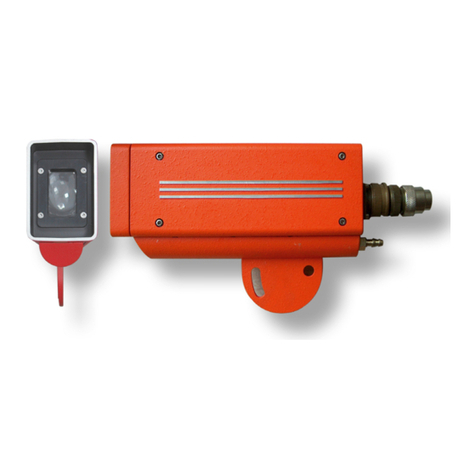
Danieli Automation ID2202 User manual

Installation, use and maintenance manual
23
ID2202
INFRARED PHOTODETECTOR
Installation, use and maintenance manual
Contents
1
INTRODUCTION 24
1.1
O
PERATING
P
RINCIPLE
24
1.2
F
IELDS OF APPLICATION
24
2
TECHNICAL SPECIFICATIONS 25
3
DESCRIPTION 26
3.1
E
XTERNAL APPEARANCE
26
3.2
E
LECTRICAL INTERFACE
27
3.3
S
ENSITIVITY CONTROL POTENTIOMETER
29
3.4
LED
LAMPS
29
4
REPLACING ID2000 AND ID2200 MODELS 31
4.1
I
NPUT AND OUTPUT COMPATIBILITY
31
5
INSTALLATION 32
5.1
S
AFETY
32
5.2
T
RANSPORT
32
5.3
P
OSITIONING
32
5.4
P
ROTECTION FROM LIGHT RADIATION
35
5.5
C
OOLING
36
5.6
S
IGHTING
36
5.7
S
ENSITIVITY CONTROL
36
6
MAINTENANCE 38
6.1
O
PERATIONAL
T
EST
38
6.2
P
ERIODIC INSPECTIONS
38
6.3
C
LEANING THE OPTICAL WINDOW
38
6.4
R
EPLACING THE OPTICAL WINDOW
38
6.5
T
ROUBLESHOOTING
39
7
CONTENT OF THE PACKAGE SUPPLIED 40
8
SPARE PARTS / ACCESSORIES 40
9
ACCESSORIES 40
10
ADDITIONAL INFORMATION 41
10.1
O
VERALL
D
IMENSIONS
41
11
TECHNICAL ASSISTANCE 42
Danieli Automation Standard - Installation Use and Maintenance Manual - ID2202
Certified by OneDoc A.620.107 Rev.04-MU 24/145 #1061394

Danieli Automation – ID2202
24
1 I
NTRODUCTION
The ID2202 (code D.A. 5122000031) is a device, of the ON/OFF type, that detects the presence of hot
materials, that is to say, materials that emit infrared radiation (IR).
The ID2202 can replace, with additional functions and improved features, the ID2200 and ID2000
models.
1. Photodector ID2202
1.1 O
PERATING
P
RINCIPLE
The ID2202 uses an IR sensor to measure the quantity of infrared radiation that is present in its field of
view.
A digital output is activated in the presence of hot material, or when the output signal of the sensor IR
exceeds a threshold value, which can be set by a potentiometer.
A second digital output provides an indication of the reliability of the detection, signalling anomalies in
its functioning or excessive closeness to the threshold of detection, and therefore a possible error.
A digital input allows you to select the HMD sensitivity, so as to ensure a reliable detection of both
‘cold’ (T > 450°C), and ‘hot’ (T > 650°C) material s.
1.2 F
IELDS OF APPLICATION
The ID2202 is designed specifically for use in steel hot rolling mill plants, but it can also be used in
similar applications (i.e. continuous casting, or detection of the presence of hot bodies in non-ferrous
metals).
The manufacturing characteristics of the photodetector make it suitable for use in heavy industrial
environments.
The photodetector is prepared for electrical supply by low-voltage continuous current. The output
connectors are protected against overloads and over voltages.
Danieli Automation Standard - Installation Use and Maintenance Manual - ID2202
Certified by OneDoc A.620.107 Rev.04-MU 25/145 #1061394

Installation, use and maintenance manual
25
2 TECHNICAL
SPECIFICATIONS
Detectable spectrum 850 .. 1700 nm
Temperature of the object to be
detected
≥450°C (842°F) HIGH sensitivity
≥650°C (1202°F) LOW sensitivity
Distance of detection (fig. 7) 500 .. 2,000 mm
Range of the observation field (fig. 8) vertical: 12°
horizontal: 3°
Digital inputs 24 Vdc / 5 mA
Digital outputs PNP, Imax = 200 mA, output connections protected
against short circuits.
Response time
ON
OFF
typ. 0.2 ms (min 0.1, max 0.3 ms)
typ. 0.3 ms (min 0.2, max 0.5 ms)
Power supply rated voltage 24 Vdc (20 .. 32Vdc) @ 50mA
Power supply of cooling device water, filtered < 300 µm, 3-5 L/min @ 0.2 bar, 2 bar max
1/4” GAS threads
Working temperature -40 .. +70 °C (-40 .. 158 °F)
Storage temperature -40 .. +70 °C (-40 .. 158 °F)
Degree of protection IP66 (NEMA 4X)
Dimensions (not including connectors) 266 x 180 x 64 mm (10.5” x 7.1” x 2.5”)
Weight 1.7 kg (3.7 lb)
Danieli Automation Standard - Installation Use and Maintenance Manual - ID2202
Certified by OneDoc A.620.107 Rev.04-MU 26/145 #1061394

Danieli Automation – ID2202
26
3 DESCRIPTION
3.1 E
XTERNAL APPEARANCE
The container of photodetector ID2202 (1), made of pressure-cast aluminium, is equipped with a semi-
circular support plate (2) that allows its fastening and orientation on the vertical plane within an angle of
about 30°, and incorporates a circuit for liquid cooling (3), to be supplied with water or other
refrigeration fluids based upon the working environmental conditions.
There is an optical window (4) on the front side through which the IR sensor inside the HMD “observes”
the material to detect.
A green LED, that is inside the HMD, can be seen through the optical window.
2. Exterior appearance
On the rear side of the photodetector there are the following connection and signalling devices:
bayonet connector, 6 contacts, directive MIL-C-5015 (5)
two-colour red/green LED (6)
potentiometer to adjust sensitivity (7)
1/4" GAS threads to supply and drain the cooling circuit (8).
3. Rear view
Danieli Automation Standard - Installation Use and Maintenance Manual - ID2202
Certified by OneDoc A.620.107 Rev.04-MU 27/145 #1061394

Installation, use and maintenance manual
27
3.2 E
LECTRICAL INTERFACE
All the signals are reported to the 6-pole circular connector, MIL-C-5015 type, located on the rear side
of the photodetector.
We recommend cabling the signals of the connector to an intermediate junction box located near the
rolling line, easily accessed for inspection and maintenance. The junction box should represent the
connection point with the automation system.
Pin Signal Function
A +24VDC
D 0VDC Power input
C MATP Presence of material, digital output PNP
B HEALTHY Reliable detection, digital output PNP
F TEST Test, digital input
E SSEL Sensitivity selection, digital input
4. Circular connector
5.
Electrical connections
Danieli Automation Standard - Installation Use and Maintenance Manual - ID2202
Certified by OneDoc A.620.107 Rev.04-MU 28/145 #1061394

Danieli Automation – ID2202
28
MATP – presence of material
The MATP digital output is activated when an infrared source of intensity sufficient to exceed the
detection threshold, which is determined by the sensitivity selection (“coarse” control) and the position
of potentiometer (“fine” control), is detected.
HEALTHY – reliable detection
The HEALTHY digital output is normally activated and deactivated when one of the anomalies
indicated below is present:
the IR signal received is near the threshold, and therefore the detection is uncertain
the TEST input is activated but the IR sensor does not detect a sufficient signal
internal overheating
absence of power supply
Simultaneously with the deactivation of the HEALTHY output, the anomaly is indicated also by the two-
colour LED located on the rear of the ID2202.
TEST – self-test
When enabled, an IR LED located in front of the sensor is switched on, causing the MATP output to
activate.
SSEL – sensitivity selection
It is possible to select the “coarse” sensitivity of the detector ID2202 by activating or not the SSEL
digital input, that is to say connecting it or not to the power supply.
The potentiometer located on the rear panel provides the fine control.
SSEL Sensitivity
OFF HIGH (like ID2200 )
ON LOW (like ID2000 )
The SSEL input may be:
reported on an external clamp with a configuration jumper
piloted by a PLC output, to set dynamically the sensitivity according to the temperature of the
material to detect.
Note that, if the SSEL input is not connected, the sensitivity selected is HIGH.
ATTENTION !
It is necessary to set the sensitivity on HIGH if the temperature of the material is near the lower
measurable limit.
We recommend not using the HIGH selection if not necessary, given that it increases the probability of
detection of sources outside the process (reflections of material or solar radiation).
Danieli Automation Standard - Installation Use and Maintenance Manual - ID2202
Certified by OneDoc A.620.107 Rev.04-MU 29/145 #1061394

Installation, use and maintenance manual
29
3.3 S
ENSITIVITY CONTROL POTENTIOMETER
The single-turn potentiometer, located on the rear panel, provides the fine control of the material
presence threshold and also allows you to set the ID2202 detection sensitivity. The potentiometer’s
shaft is equipped with a shock-proof protection and can be activated by means of a screwdriver.
The diagram shows the minimum detectable temperature for a rolled product having 10 mm diameter,
placed at a distance of 500 mm from the front glass, depending on the position of the potentiometer,
and according to the selected sensitivity through SSEL input.
For instance, if the potentiometer is at 100% (maximum sensitivity), the minimum detectable
temperature is 450°C if SSEL = OFF (high sensitivity), or about 640°C if SSEL = ON (low sensitivity).
The minimum detectable temperature varies according to the rolled product diameter and distance.
6.
Minimum detectable temperature depending on the potentiometer position
3.4 LED
LAMPS
There are two: one front LED lamp and a rear LED lamp.
The front LED, high-brightness green, that can be seen through the optical window, is activated along
with the rear green LED and at the MATP output when presence of material is detected.
The LED allows the operator, provided with an electric torch (with filament lamp) to identify where the
ID2202 field of view is. The operator comes in front of the HMD and moves the torch (aimed at the
HMD) in the area where it is assumed the HMD’ field of view is. Sighting can be precisely identified by
the corresponding switching on of the LED.
The two-toned green/red LED on the rear panel is activated in the following conditions:
the green colour switches on in the presence of material
if the light intensity received is near the threshold of material detection, the red light flashes more
and more rapidly as the threshold comes closer (at the same time the HEALTHY output is
deactivated)
the red light flashes slowly for internal overheating (at the same time the HEALTHY output is
deactivated).
The red light flash in the absence of a bar indicates that the background light detected in the reading
field is too strong and might compromise the accuracy of the reading.
The red light flash in the presence of a bar (together with the activation of the green-coloured LED)
indicates that the signal is weak and therefore very close to the threshold of detection that determines
the presence of the bar.
Low Sensitivity
High Sensitivity
Danieli Automation Standard - Installation Use and Maintenance Manual - ID2202
Certified by OneDoc A.620.107 Rev.04-MU 30/145 #1061394

Danieli Automation – ID2202
30
The following table summarises the signals of the rear LED.
Suggestions
Verify / improve the proper
sighting and/or installation
Material is too cold or selection of
sensitivity is inadequate
Analyse what causes the
overheating:
- exposure to sources of heat
- excessive ambient temperature
Output status
MATP = OFF
HEALTHY = ON (if photocell switched on)
MATP = OFF
HEALTHY = OFF
MATP = ON
HEALTHY = OFF
MATP = ON
HEALTHY = ON
MATP = ON/OFF according to the
presence or not of material
HEALTHY = OFF
Description
ABSENCE OF MATERIAL, or photocell switched
off
RELIABLE DETECTION (if photocell switched on)
ABSENCE OF MATERIAL
Signal near the threshold of presence of material
(anyway below the threshold) The LED flashes
more and more frequently as the signal
approaches the threshold
PRESENCE OF MATERIAL
Signal near the threshold of presence of material
(anyway above the threshold) The LED flashes
more and more frequently as the signal
approaches the threshold
Detection is NOT RELIABLE
PRESENCE OF MATERIAL
Signal beyond the threshold of presence of
material.
Detection is reliable
OVERHEATING
The photocell can keep operating normally.
Rear LED status
GREEN LED = OFF
RED LED = OFF
GREEN LED = OFF
RED LED = Short pulses
GREEN LED = ON
RED LED = Short pulses
GREEN LED = ON
RED LED = OFF
GREEN LED = OFF
RED LED = 1Hz Flashes
Danieli Automation Standard - Installation Use and Maintenance Manual - ID2202
Certified by OneDoc A.620.107 Rev.04-MU 31/145 #1061394

Installation, use and maintenance manual
31
4 REPLACING
ID2000
AND
ID2200
MODELS
The ID2202 is designed to replace, with improved features, the following models:
ID2000: HMD for high temperatures
ID2200: HMD for low temperatures
Improved features are:
SSEL input to select the sensitivity, depending on its setting, thus allowing to use the ID2202 both
as ID2000 and ID2200. So it is possible to use just one HMD’s model in several parts of the plant,
where the rolled product temperature is different.
The SSEL input allows using the ID2202 in plant areas where the rolled product temperature is
high or low depending on the product, for instance at the exit of a water box that can be switched
On or Off. To set the most appropriate sensitivity is sufficient that automation controls adequately
the SSEL input.
The ID2202 horizontal visual angle is narrower and more accurate as to ID2000 and ID2200, so
that accuracy of detection is improved.
If the ID2202 is used to replace ID2000 (SSEL=1), its insensitivity to sunlight is 100 times more
than ID2000’s.
Two-toned rear LED which signals when the IR signal received is near the presence of material
threshold, and therefore the detection is uncertain
Digital output to signal proximity to the presence of material threshold, and other malfunctions.
Front LED of presence of material (in addition to the rear one) so as to make easier the sighting
check.
4.1 I
NPUT AND OUTPUT COMPATIBILITY
the ID2202 is electrically compatible with ID2000 and ID2200 models, with the following exceptions:
the ID2202, differently from ID2000 and ID2200, does not have the NPN output of presence of
material (pin B). On this pin ID2202 has the HEALTHY output, PNP type
To enable the test function, it is necessary that ID2000 and ID2200 apply a 24V between the pins F
and E. In ID2202, instead, the test function is enabled by applying 24V just on pin F, whilst pin E is
used as input for selecting the SSEL sensitivity.
Example ID2200, wired as follows:
only the PNP output of presence of material is used (the most common case)
the TEST function is enabled by applying 24V to pin F and 0V to pin E.
In this case it is possible to replace ID2200 with ID2202, without any wiring change. Since the pin E is
connected to 0V, ID2202 shall have a high sensitivity setting, that is a sensitivity similar to ID2200.
Thus, change of wiring is avoided, but obviously the additional functions of ID2202 (SSEL output and
HEALTHY) are lost. If HMD is installed at the exit of a water box which may be off or on (therefore
HMD should detect a hot or cold material), it may be advisable cabling at least the SSEL input to a PLC
so as to dynamically set sensitivity.
Example ID2000, wired as follows:
only the PNP output of presence of material is used (the most common case)
the TEST function is enabled by applying 24V to pin F and 0V to pin E.
In this case ID2000 can be replaced by ID2202, but it is necessary to change cabling so as to connect
the pin E (SSEL) to 24V, and then to set low sensitivity (similar to ID2000).
As an alternative the original wiring can be kept and the adjusting potentiometer be turned to the
minimum. The resulting sensitivity shall be similar to that of ID2000.
Danieli Automation Standard - Installation Use and Maintenance Manual - ID2202
Certified by OneDoc A.620.107 Rev.04-MU 32/145 #1061394

Danieli Automation – ID2202
32
5 INSTALLATION
To obtain the maximum reliability of detection it is necessary to effect a correct installation of the
detector, taking into account the field of measurement, the minimum dimension of the material as a
function of distance, and applying the precautionary measures reported here below.
5.1 S
AFETY
The ID2202 photodetectors are intrinsically safe devices because they operate at a low voltage and do
not have dangerous parts. However, they should be used and maintained only by skilled personnel
who are fully acquainted and comply with all the instructions contained in this manual.
5.2 T
RANSPORT
All parts of the photodetector are transported in a box. Inside the box there are suitable polystyrene
compartments for the safe transport of the device. The package should be kept so as to be used for
transport in case of extraordinary maintenance or repair.
5.3 P
OSITIONING
The distance between the photodetector and the material to detect must be determined following the
indications given in the diagram of fig. 7.
In the diagram, for SSEL = OFF (SENS = HI, HIGH sensitivity) and SSEL = ON (SENS = LOW, LOW
sensitivity) respectively, lines represent the maximum installation distance based on different
diameters of the rolled product.
The diagram gives the value of the permissible maximum installation distance for the operator,
according to the estimated or measured temperature of the material.
ATTENTION !
The diagram gives the maximum distance of use. We recommend to install the HMD at a lower
distance than the maximum allowed, for ex. at 60% so as to maintain an adequate margin of safety for
detection.
D
optimum
≤60% x D
max
On the contrary, when rolling hot products, with a very short distance the photodetector may become
overheated.
Example
The ID2202 must be installed to detect a material with minimum temperature of 480°C, and a minimum
dimension of 10mm. What is the ideal distance for installation?
Should ID2202 detect “low” temperatures, it must be set with high sensitivity (SENS = HI).
In the diagram, curve corresponding to D=10, shows a maximum distance of about 800mm.
The ideal distance for installation should be less than 60% the maximum distance, for instance
480mm.
Danieli Automation Standard - Installation Use and Maintenance Manual - ID2202
Certified by OneDoc A.620.107 Rev.04-MU 33/145 #1061394

Installation, use and maintenance manual
33
7. Maximum distance of use varies according to the rolled product’s temperature and dimension.
8. Angle of horizontal reading
Danieli Automation Standard - Installation Use and Maintenance Manual - ID2202
Certified by OneDoc A.620.107 Rev.04-MU 34/145 #1061394

Danieli Automation – ID2202
34
Figure 9 shows the width of the field of measurement based upon the distance of use. The field of view
is essentially a rectangle with the dimensions shown in the figure.
The detector must be placed at such a distance that the field of measurement covers all the positions
in which it can find material to be detected.
9. Material detection field in relation to distance
The ID2202 is normally installed to the side or above the rolling line. Avoiding a down to top orientation
would be better because dust and scale could soil the optical window, preventing its correct operation.
When possible it is better to install the ID2202 to the side of the line.
It is necessary to avoid that fumes or steam reduce the visibility of the material, preventing a correct
measurement (fumes and steam may be removed blowing air at low discharges, using for example an
industrial fan).
ATTENTION !
Avoid fastening the detector onto structures subject to vibrations.
Between the detector and bars there must not be any objects, still or moving, that can interfere with
detection.
It may be opportune to equip the photodetector with mechanical and additional thermal protection that
guard it against accidental impacts or direct radiation from material. In figure 14 we see a possible
example of support with protection, designed to permit, when necessary, rapid access for any
operations of adjustment and/or maintenance.
If protection is present between the material and the detector, arrange that protection with a window of
sufficient width so that the material is visible for a section long at least as the detection field width.
Danieli Automation Standard - Installation Use and Maintenance Manual - ID2202
Certified by OneDoc A.620.107 Rev.04-MU 35/145 #1061394

Installation, use and maintenance manual
35
5.4 P
ROTECTION FROM LIGHT RADIATION
It is necessary to avoid sources of light or infrared radiation extraneous to the process (light-bulbs,
windows, reflections from the rolled product, etc.) that might be within the observation field of the
detector.
Correct installation shown in fig. 10: the observation field of ID2202 is from top to down, while a screen
protects it from external light sources.
10.
Example of correct positioning
Incorrect installation shown in fig. 11:
the observation field of ID2202 is from down to top (non opportune)
light sources affect the ID2202, thus increasing the risk of incorrect detection.
11.
Example of incorrect positioning
Protection screen
Danieli Automation Standard - Installation Use and Maintenance Manual - ID2202
Certified by OneDoc A.620.107 Rev.04-MU 36/145 #1061394

Danieli Automation – ID2202
36
NOTE: if set to “LOW sensitivity” (instead of "HIGH"), the detection threshold is higher, and the ID2202
is able to operate in conditions of greater background light.
ATTENTION !
The presence of reflective surfaces within the reading field of the ID2202 (for example ducts or rolls)
may cause uncertainties in the reading, and are therefore to be avoided. A non-reflective screen must
be present behind the rolled product (opaque black), better if built-in, to avoid that light reverberations
might reach the detector.
5.5 C
OOLING
If the ambient temperature is likely to exceed 60 °C it is opportune to activate the cooling circuit
provided on the photodetector body to reduce the temperature so that it falls within the maximum limit.
ATTENTION !
Water (or other refrigeration fluid) must be used only in real need. Excessive cooling of the
photodetector body with respect to the ambient temperature may cause the formation of condensation,
due to environment humidity, on the device itself and on the glass window, with consequent risks for its
correct functioning.
If the cause of the higher temperature of the photodetector is radiation deriving from the rolled product,
we recommend the use of protective screens against the radiation, generally a more effective solution
than water cooling.
In the event of overheating due to direct radiation, which cannot be avoided, use a cooled protection
(see chapter 8).
5.6 S
IGHTING
To verify sighting, use an infrared source – for example an electric torch or a piece of heated bar –
positioned in the area where the material will move, pointed toward the optical window of the ID2202.
Verification occurs by moving the torch throughout the area in which the material will be located, and
checking for the corresponding activation of the bar presence indicator.
5.7 S
ENSITIVITY CONTROL
The ID2202 is provided with an input for the “coarse” sensitivity control (SSEL), and with a
potentiometer for the fine control.
The potentiometer setting can be typically maintained at 100% and act only on the SSEL input.
If the material to detect is always “hot”, set SSEL=1 (low sensitivity)
If the material to detect is always “cold”, set SSEL=0 (high sensitivity)
When the temperature of the material may be high or low, depending on the rolling process, wire
the SSEL to a PLC output and control it opportunely according to the optimal sensitivity.
Danieli Automation Standard - Installation Use and Maintenance Manual - ID2202
Certified by OneDoc A.620.107 Rev.04-MU 37/145 #1061394

Installation, use and maintenance manual
37
Especially when the ID2202 is set to high sensitivity, it could be useful, anyway, to act on the adjusting
potentiometer, for instance in the occurrence of false detection, or when, in the absence of the bar, the
red LED flashes to indicate that the signal level is near the threshold value.
The ideal condition, in fact, will be that:
in the absence of material, the green LED is off, the red LED not flashing (which, anyway, would
indicate that the sensor detects a light level that is near the detection threshold)
in the presence of material, the green LED is on, the red LED not flashing (which, anyway, would
indicate that the IR signal is low and near the detection threshold).
In the first case (flashing in the absence of material) we recommend reducing sensitivity, while in the
second case it would be better to increase it.
LED flashing can be useful to determine the low limit of sensitivity and to define a safety margin.
in the presence of material, when rolling a “cold” material of small size, reduce sensitivity until the
LED starts flashing slowly, which means that a detection threshold is approaching.
From this position increase again sensitivity until the LED stops flashing, then turn slightly the
potentiometer so as to get a reasonable margin of detection.
Please remember that the HEALTHY output is disabled when the amount of IR signal is near the
threshold, that is when the LED lamp starts flashing. If this output is wired at a PLC output, it can be
used to check when the threshold is approaching, what affects reliability of detection negatively
(incorrect detection or loss of detection).
Danieli Automation Standard - Installation Use and Maintenance Manual - ID2202
Certified by OneDoc A.620.107 Rev.04-MU 38/145 #1061394

Danieli Automation – ID2202
38
6 M
AINTENANCE
6.1 O
PERATIONAL
T
EST
The TEST input enables an infrared source inside the photodetector, in front of the sensor, to switch
on. The MATP output is enabled accordingly.
This action allows verification of the correct functioning of the optical electronic devices and the links
between the detector and the equipment connected.
A test sequence may be activated by the system automation, in the time intervals during which the bar
to detect is not present (ghost rolling).
6.2 P
ERIODIC INSPECTIONS
Periodic preventive maintenance of the photodetector includes the following inspections:
Check that sighting is correct, using an incandescent bulb located in the area in which the material
to be measured will move
Check that screening of ambient lighting is correct, using the information provided by the warning
lamp in the absence of bars
Check that photodetector is fastened to its support: stability and sighting.
Check the optical path and remove any deposits of scale that may form in the detection field
Check that protections supplied with the device are in working order.
Check the glass window of the photodetector, clean or replace, if necessary.
Check connector and electrical cable condition, clean or replace, if necessary.
ATTENTION !
Do not use water machine for the external cleaning of the photodetector.
6.3 C
LEANING THE OPTICAL WINDOW
A clean cloth must be used to clean the optical window, paying attention not to scratch the glass
6.4 R
EPLACING THE OPTICAL WINDOW
Replacement of the optical window becomes necessary when it is seriously damaged (scratched or
broken) or insufficiently transparent.
The replacement operation must be performed in a clean environment, for example in an office. Clean
the outside of the detector if dirty, so as to avoid dirt falling into the device during replacement of the
window. The operator’s hands must also be clean.
To replace the optical window:
Remove the 4 screws that fasten the glass locking flange
Remove the glass and replace
Carry out the operations above in reverse order, paying particular attention to the assembly of the
seal located between the glass and the detector.
Danieli Automation Standard - Installation Use and Maintenance Manual - ID2202
Certified by OneDoc A.620.107 Rev.04-MU 39/145 #1061394

Installation, use and maintenance manual
39
6.5 T
ROUBLESHOOTING
Whenever a malfunction of the photodetector is signalled, proceed as follows:
Carry out the checks indicated in the periodic maintenance, as explained in chapter 6.2.
Check functioning by the Self-Test (chapter 3.2).
If the Self-Test works:
check the glass window condition, clean or replace, if necessary
check the sighting and adjust, if necessary
verify sensitivity setting according to the object to detect
If the Self-Test does not work:
check that the power supply is present,
check the connector,
check the external cabling.
Danieli Automation Standard - Installation Use and Maintenance Manual - ID2202
Certified by OneDoc A.620.107 Rev.04-MU 40/145 #1061394

Danieli Automation – ID2202
40
7 CONTENT
OF
THE
PACKAGE
SUPPLIED
(1) ID2202
(2) CD plus Quick Reference
(3) Connection cable
(4) Replacement glass
12. Complete supply
8 SPARE
PARTS
/
ACCESSORIES
Description Code D.A.
Complete ID2202 detector 5122000031
Protection glass 3985000035
Connection cable, L=2m (6.6 ft) 5331000239
9 ACCESSORIES
Description Code D.A.
Cooled protection 5915000475
Front protection with air cleaning 5915000450
(1)
(2
)
(3
)
(4
)
Danieli Automation Standard - Installation Use and Maintenance Manual - ID2202
Certified by OneDoc A.620.107 Rev.04-MU 41/145 #1061394

Installation, use and maintenance manual
41
10 ADDITIONAL
INFORMATION
10.1 O
VERALL
D
IMENSIONS
Figure 13 shows the overall dimensions of the photodetector.
Figure 14 shows an example of construction of a support, designed to contain and protect the ID2202
photodetector.
13. Dimensions of the detector (DIN reference mm)
Danieli Automation Standard - Installation Use and Maintenance Manual - ID2202
Certified by OneDoc A.620.107 Rev.04-MU 42/145 #1061394

Danieli Automation – ID2202
42
14. Recommended support (DIN reference mm)
11 TECHNICAL
ASSISTANCE
z AUTOMATION technical assistance service is available to provide users with information and
explanations, and to obtain the support necessary for repairs and maintenance.
Contact the customer assistance office by phone, fax or e-mail:
tel: +39 0432 518999
fax: +39 0432 518188
Danieli Automation Standard - Installation Use and Maintenance Manual - ID2202
Certified by OneDoc A.620.107 Rev.04-MU 43/145 #1061394
This manual suits for next models
1
Table of contents
Other Danieli Automation Security Sensor manuals
Popular Security Sensor manuals by other brands

Dalsa
Dalsa Shad-o-Scan 3001 user manual

ESYLUX
ESYLUX COMPACT PD-C 360/8 BMS DALI-2 operating instructions

schmersal
schmersal EX-BNS 180 Series operating instructions

Di-soric
Di-soric DCC 12 VHD 2 PS-B3-56-7 quick start guide

Beko
Beko METPOINT CID Operation manual

DINUY
DINUY KNX DM KNT 003 instruction manual

Omron
Omron F3SG-SR Series manual

Model Train Technology
Model Train Technology NANO PRECISION DETECTOR 2 Operation manual

Climax Technology
Climax Technology ACGS-23 quick start guide

Philips
Philips OccuSwitch LRM1771 installation guide

System Sensor
System Sensor 2151 Installation and maintenance instructions

Autel
Autel MX-SENSOR quick start guide