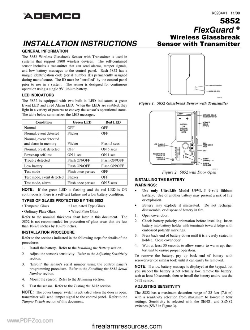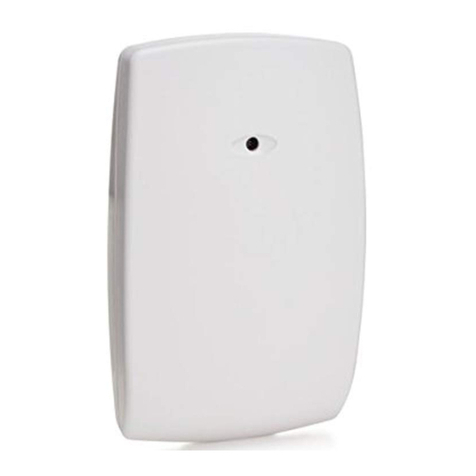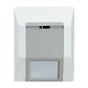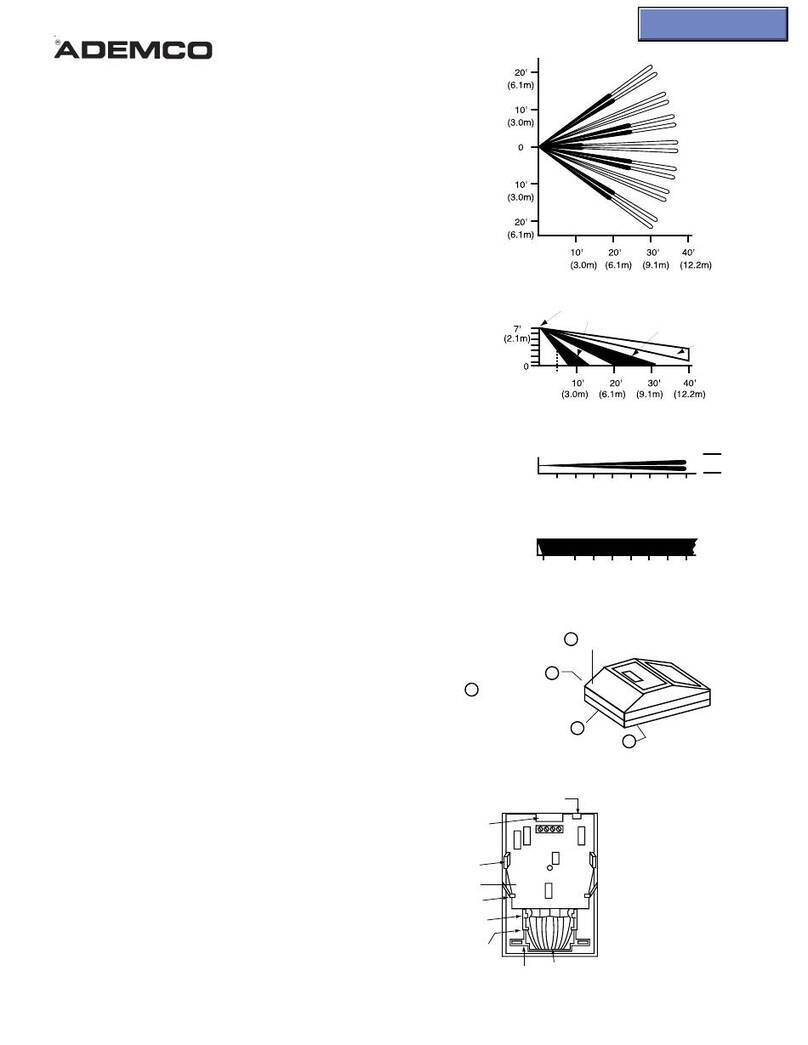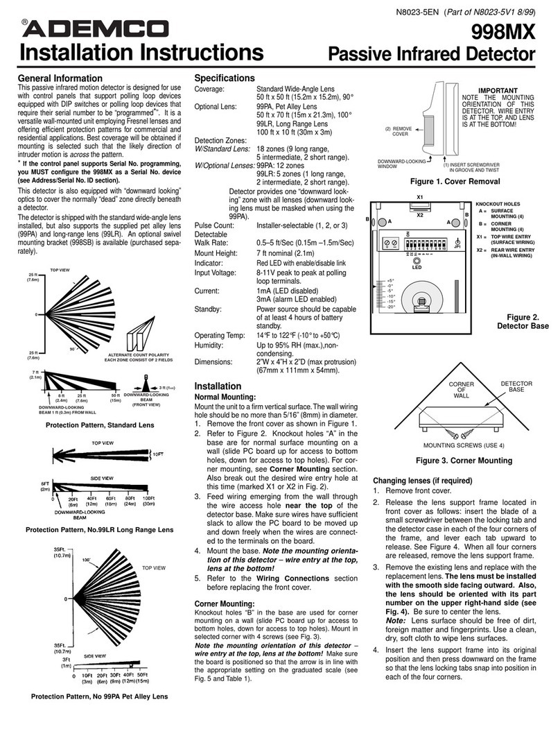
Selecting a Mounting Location:
BeoatJSe the Nos. 652 and 653 passive Infrared Detectors respond to changes in energy which occur when an intruder
moves into or out of a zone, best coverage will be obtained if the mounting site is selected such that the likely direction of
intruder
motion
is ACROSS the pattern. See Diagrams 6a, band c.
In a
hallway,
aitie or narrow room, a No. 853 unit should be aimed directly down the center of the area; the intermediate
zones will prevent an intruder from avoiding detection by following the wall. See Diagram 7a.
An alternative approach is to angle the main zones from “comer-to-comer”. See Diagram 7b.
Avoid direct viewing, by the unit, of heat sources such as radiators, heating ducts, direct sunlight. etc.
INSTALLATlON AND WlRlNG:
Passive I.R. units are remarkably resistant to false alarm hazards but the following recommendations should be observed:
Avoid locating unit where central heating radiators, live fires or heating outlet ducts could be within the pro&five zones.
Avoid locating the unit indirect sunlight or directly above strong sources of heat.
Avoid locating unit on unstable surfaces.
Avoid running alarm wiring close to heavy duty electrical cables.
Mounting:
IMPORTANT:
Be careful during installation or adjustment NOT TO TOUCH THE REFLECTOR OR SENSOR SURFACES.
1. Mount the wall plate to afirm and vertical
surface (flat on wall or in comer), .asshown in Diagram 8, at the recom-
mended height (see previous section). Orient the plate so that the rectangular cutout in the plate is at the bottom. ff
wiring is provided from a hole in the mounting surface, locate the mounting plate so that the wiring hole is centered
horizontally within the rectangular cutout in the plate and the bottom edge of the plate is positioned in-line with the
center of the wiring hole. See Diagram 8, Detail A. This will align the wiring hole with the wiring entry in the case when
the unit is secured.
Wiring holes should be no larger than
‘/16”
(0.8 cm) in diameter.
2. Removethe front co-r from the detector
by loosening the retaining screw.
3.
Attach the unit to
the wall
plate
as follows: Engage all four hooks on the wall plate into the slots on the rear of the
case (See Diagram 8) and secure the unit to the wall plate by,pressing downward.
4. After wiring (see next section) install the
wire
entry plug provided, replace front cover and secure retaining /‘\
screw.
_\ i
NOTE:
With front cover secured in place, unit is locked to wall mounting plate. To detach unit from wall plate, front cover
must be removed first. -
Wiring Connections;
Using the wire entry plug and the wiring entry access at thefower rear of the case, carefully feed the wires through the entry
and along the underside of the terminal block.
Avoid unnecessary splices and loops within the unit. Check all connections carefully.
SeeDiagram 9for connections,
which should be made in this order:
1.Alarm Relayand TamperTerminals:
To connect a closed circuit protective loop, see diagram. Connect tamper
switch circuitry as desired.
2. Control Signal Terminal and Options: See
OPTIONAL OPERATING MODES. ff one of the options is to be
selected, run the necessary control lead(s) between the detector and the main control and cut the required jumper(s).
3. Optional Remote LED
Post: If remote LED operation is desired, connect as shown in diagram. Also cut the YEL-
LOW jumper on the circuit board. Note: The side of the LED that is not connected to the remote LED post may be
connected directly to the DC source ground (if the wire length is shorter). OBSERVE POLARITY!
4. Input 6V112V.DC(+ 1and (-1 Terminals:
Connect these terminals to a 6V.DC or 12V.DC source that can
provide 35mA continuously Note: For 12VDC operation, cut the unit’s ORANGE jumper.
Observe polarity!
Continuous auxiliary capacity of applicable Ademw controls is as follows:
-I
No. 1021.4021: 400mA No. 1025: 220mA
6VDC No. 1022: 150mA No. 4080,408OXL: 500mA
No. 1023: 350mA No. 33OR25,340R25: 250mA
No. 1024: 260mA No. 332R50,342R50: 750mA
I
No. 1021-l 2.4021-l 2: 400mA No. 1025-l 2: 1025EX12: 220mA
12V.DC No. 1022-l 2: 300mA No. 4080-l 2: 500mA
No. 1023-12: 550mA
Altematively,‘GV.DC can be conveniently provided directly from any 24 hour 12OV.ACoutlet via a No. 495 Power Supply
which plugs directly into the outlet.
100
94
www.PDF-Zoo.com
