DanTaet System KMP-V User manual

DanTaet System KMP-V
User Manual
Højmevej 36-38
DK-5250 Odense SV
Pho +45 63 17 45 00
Fax +45 63 17 45 01
Program 110101 func.spec. 160926

DanTaet a/s
User Manual System KMP-V
110101 func. spec. 160926
Doc.No. 417106
Revision 170823
Page 2 of 26
Table of Contents
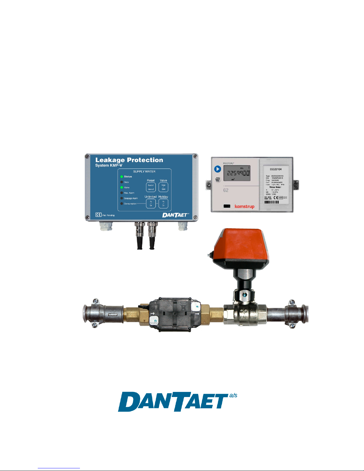
System KMP-V.......................................................................................................3
Overview..............................................................................................................3
Monitoring..............................................................................................................4
Max.Alarm............................................................................................................4
Seepage Alarm....................................................................................................4
System Test.........................................................................................................4
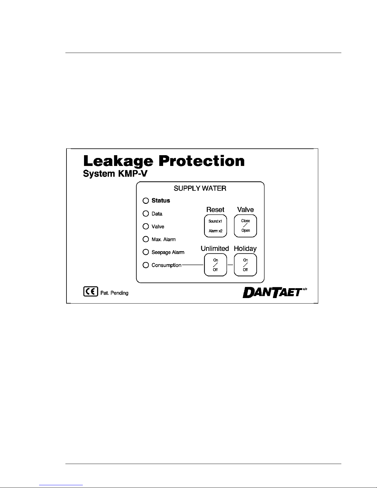
Operation ...............................................................................................................5
Operating Modes...................................................................................................6
Manual Phase Switching....................................................................................6
Automatic Phase Switching (External Input)...................................................6
Automatic Phase Switching (PIR).....................................................................6
Special Functions .................................................................................................6
Normal operation without disturbance ............................................................7
Normal operation with disturbance ..................................................................7
Leakage Alarm Condition ..................................................................................7
System Error Condition .....................................................................................7
Liquid Sensor wet/defective ..............................................................................7
Normal Operation...............................................................................................8
Disturbance ........................................................................................................9
Leakage Alarm Condition.................................................................................10
System Error Condition....................................................................................11
Liquid Sensor wet.............................................................................................12
Liquid Sensor defective....................................................................................13
External Control ..................................................................................................14
DIP1: ABA..........................................................................................................14
DIP2: AIA ...........................................................................................................14
Digital Outputs ....................................................................................................15
Liquid Sensor Option..........................................................................................16
Functional test of liquid sensor.........................................................................16
Liquid Sensor Interface ILS-C............................................................................17
Checking and Setting the Clock ........................................................................18
Checking the Clock ..........................................................................................18
Setting the Clock ..............................................................................................18
Checking and setting the Free time ..................................................................19
Checking the Free time ....................................................................................19
Setting the Free time ........................................................................................19
Plumbing ..............................................................................................................20
Meter ..................................................................................................................20
Cut-off Valve......................................................................................................20
Socket and Gland Identification ........................................................................21
Electrical Installation ..........................................................................................22
Setting the Monitoring Function........................................................................23
Jumper row A-D: Monitoring Parameters .......................................................24
Jumper row E: Relay Configuration ................................................................24
Jumper row F: Options....................................................................................24
Seepage Tolerance...........................................................................................25
Function Select for digital inputs....................................................................25
EU Declaration of Conformity ............................................................................26

DanTaet a/s
User Manual System KMP-V
110101 func. spec. 160926
Doc.No. 417106
Revision 170823
Page 3 of 26
System KMP-V
DanTaet System KMP-V is a leakage protection system for supply water installations.
The system comprises a Kamstrup ultrasonic water meter MULTICAL
62, a leakage
detection unit KMP-V and an electrically actuated cut-off valve. The valve is connected to
the KMP-V via a DIN plug, and the water meter is connected via a data link to the
KMP-V, which fetches flow readings from the water meter.
The KMP-V front panel features six indicators and four control buttons:
Overview
The Status indicator signals the actual system condition thus:
Steady Green: System operational and monitoring, no leak.
Flashing Green: System operational, running-in.
Steady Yellow: System operational with valve error
Extinguished: Installation cut off. If ’Seepage Alarm’ flashes green, the valve
tightness test is executing. If ’Max. Alarm’ or ’Seepage Alarm’ displays
a steady or flashing red, the system is in the leakage alarm state.
Flashing or
steady Red: A critical system error has occurred; leakage protection is inoperative,
contact a qualified DanTaet service technician.

DanTaet a/s
User Manual System KMP-V
110101 func. spec. 160926
Doc.No. 417106
Revision 170823
Page 4 of 26
Monitoring
Max.Alarm
If water is discharged continuously until the set limit is exceeded, a Max. Alarm is issued,
and the installation is cut off. The flow above which consumption is considered a
discharge is adjustable, permitting adaptation of the system to the various minimum flows
of different installations. Discharge monitoring can be done in two phases, each with its
own discharge limit. The two phases are termed Normal/Holiday condition, High/Low
phase, or Presence/Absence. Phase transition may be governed manually from the front
panel, automatic via an external control input (burglar alarm (AIA) or external phase
switch box (timer/clock)), or automatically using motion sensors in PIR mode..
Seepage Alarm
During a 24-hour period, the system seeks a lull in consumption of a preset duration
during which consumption does not exceed a selected (small) value. If such a lull is not
located, a Seepage Alarm is issued, and the installation is cut off. With both duration and
volume selectable, the system can be adapted to the zero-point consumption of the
installation in question.
System Test
KMP-V regularly performs an automatic system self-test.
Alarm is issued for the following system errors:
Communication Error MULTICAL
water meter fails to respond
Meter Error Missing or erroneous signal from the water meter
Valve Error The valve does not shut tight
Liquid Sensor Error An attached liquid sensor is defective
Power Supply Error An internal voltage supply has failed
230Vac Error Mains Supply Failure. Alarm relay drops
System errors do not cause installation cut-off, but the system is inoperative and should
be serviced as soon as possible.

DanTaet a/s
User Manual System KMP-V
110101 func. spec. 160926
Doc.No. 417106
Revision 170823
Page 5 of 26
Operation
The KMP-V system is operated from the front panel, which is equipped with six indicators
and four buttons. Inside the front panel sits a buzzer which emits a short ’click’ sound on
legitimate key operations, a longer ’boo’ sound on some inappropriate key operations.
and a sustained beeping sound on alarms. Control functions are as follows:
Key ”Reset” Used to acknowledge alarms. First keypress mutes the
buzzer, subsequent keypress acknowledges the alarm and
resumes normal operation unless further alarms are pending.
Key ’Valve’ Used to manually cut off the installation (toggle function).
The key is inoperative when the valve is closed by other
means, and when the valve is forced open.
Key ’Unlimited’ Pressing this button commences or terminates a period in
which the discharge monitor is disabled. If not terminated
manually, the period will automatically expire after a preset
duration.
Key ’Holiday’ Pressing this button commences or terminates Holiday
mode, in which no meter indication is expected, and the
discharge limit is reduced to 20 litres (typically). This key
is inoperative in certain operating modes, notably PIR.
Indicator ”Status” Displays system condition cf. page 4.
Indicator ”Data” Emits a red flash when requesting data from the water meter,
and a green flash when receiving a reply.
Indicator ”Valve” Indicates position and status of the cut-off valve:
Extinguished: - valve absent or forced open
Steady Green - valve fully open
Flashing Green - valve opening
Flashing Red - valve closing
Steady Red - valve fully closed
Indicator ”Max.Alarm” Steady Red on leakage alarm (discharge); Flashing Red
after buzzer mute. Steady Yellow when an attached liquid
sensor type LS-X is wet or defective.
Indicator ”Seepage Alarm” Steady Red on leakage alarm (seepage); Flashing Red after
buzzer mute. Flashing Green during valve test. Steady
Yellow when an attached liquid sensor type LS-SX is wet.
Indicator ”Consumption” Extinguished in Holiday Mode. Steady Green in Normal
Mode. Steady Yellow in ’Unlimited’ and Inhibit conditions.
Red flash in PIR mode indicates a triggered motion sensor.

DanTaet a/s
User Manual System KMP-V
110101 func. spec. 160926
Doc.No. 417106
Revision 170823
Page 6 of 26
Operating Modes
Switching between monitoring phases is done manually or automatically in one of two
ways.
Manual Phase Switching
Manual Phase Switching is done using the front panel ’Holiday’ button. Holiday Mode
(Low Phase) is indicated by ’Consumption’ being extinguished, while Normal Mode is
indicated by ’Consumption’ being a steady green.
Automatic Phase Switching (External Input)
Automatic Phase Switching is achieved by connecting a signal ’Intruder Alarm Activated’
from a burglar alarm system to the KMP-V external control input J10, which forces the
system into Holiday Mode (Low Phase) with the proper DIPMODE selected (see page
28). When the burglar alarm is deactivated, the leakage detector switches back into
Normal Mode (High Phase). ’Consumption’ is extinguished in Holiday Mode (Low Phase)
and steady green in Normal Mode (High Phase).
Some installations permit using an external clock timer (Phase Switch Box) to provide the
phase switching signal when a burglar alarm signal is unavailable or unsuitable.
Automatic Phase Switching (PIR)
Automatic Phase Switching is achieved by having a signal from an attached motion
sensor force the system into Presence (High Phase) for a preset time. If no further
motion is registered during this time, the system reverts to Absence (Low Phase).
A motion sensor trigger is indicated by a red flash in ’Consumption’. Presence (High
Phase) is signalled by ’Consumption’ being a steady green, while Absence (Low Phase)
is indicated by ’Consumption’ being extinguished.
Special Functions
KMP-V can be set to meet certain particular demands.
For instance, the system may force open the valve in High Phase. This function prevents
cut-off while the building is in use, and may be used when fire hoses are integral to the
protected pipe installation. Also, the valve may be forced open by an external signal to
control input J9 (ABA) from e.g. a fire alarm. Note when fire hoses are in the protected
installation, the cut-off valve should be ordered with an SRNO actuator.
Further, the system may be set to disable the alarm output during Low Phase, for
situations where a (nightly) alarm callout is undesirable, as the system has already
isolated the installation. The alarm relay will be enabled when the building is populated
and the system switches to High Phase.

DanTaet a/s
User Manual System KMP-V
110101 func. spec. 160926
Doc.No. 417106
Revision 170823
Page 7 of 26
Function Description / Operating Modes
When operating, the system may be in one of five different operating modes
•Normal operation without disturbance
•Normal operation with disturbance
•Leakage alarm condition
•System error condition
•Liquid Sensor wet/defective
Normal operation without disturbance
When initially powered up, the system will assume the ’Normal Operation’ condition,
characterized by a steady green light in the ’Status’ indicator. On start-up, the ’Data’
indicator will emit a few fast flashes, whereafter it settles at a flash interval of 10 seconds.
Other indicators remain extinguished, except ’Valve’ indicating valve position and
’Seepage Alarm’ which will flash green for a short time during the daily valve test
procedure.
Normal operation with disturbance
The ’Status’ indicator switches to a steady yellow upon disturbance (valve error). Note
the disturbance is automatically acknowledged and reset when a new valve test
sequence is initiated. If the problem remains, the disturbance will be reported anew
during the valve test.
Leakage Alarm Condition
In Leakage Alarm Condition, the water supply is cut off, indicated by an extinguished
’Status’ indicator, red light in the ’Valve’ indicator, and red light (flashing after buzzer
mute) in an alarm indicator, and an acoustic alarm from the buzzer. The buzzer is muted
by a single ’Reset’ keypress. When all pending alarms have been acknowledged by one
or more subsequent ’Reset’ keypresses, the system will restart, opening the water
supply. The installation should be inspected for faults prior to restarting the system.
System Error Condition
System Errors render the system inoperative, and are signalled by a red light (flashing
after buzzer mute) in the ’Status’ indicator. The water supply will be unimpeded unless
the system was already in the leakage alarm condition when the system error struck.
System servicing is required.
Liquid Sensor wet/defective
A wet liquid sensor is signalled by a steady yellow light (flashing after buzzer mute) in
both alarm indicators. If the system is configured to cut off the installation for this error,
the ’Status’ indicator will extinguish, and the valve will close. A defective liquid sensor is
signalled by a steady yellow light (flashing after buzzer mute) in ’Seepage Alarm’ only.

DanTaet a/s
User Manual System KMP-V
110101 func. spec. 160926
Doc.No. 417106
Revision 170823
Page 8 of 26
Normal Operation
●Status
○Data
●Valve
○Max.Alarm
○Seepage Alarm
○Consumption
Normal monitoring.
The Data indicator
flashes red/green
every 10 sec while
communicating with
the water meter.
Consumption phase:
Low/Holiday/Absence
Valve tightness test in
progress. The water
supply is temporarily
cut off.
Consumption phase:
Low/Holiday/Absence
○Status
○Data
●Valve
○Max.Alarm
☼Seepage Alarm
○Consumption
●Status
○Data
●Valve
○Max.Alarm
○Seepage Alarm
●Consumption
A steady yellow light in the
’Consumption’ indicator
signals that the ’Unlimited’
or Inhibit function is active.
●Status
○Data
●Valve
○Max.Alarm
○Seepage Alarm
●Consumption
●Status
○Data
●Valve
○Max.Alarm
○Seepage Alarm
●Consumption
PIR mode:
A sensor has detected
motion
Consumption phase:
High/Normal/Presence

DanTaet a/s
User Manual System KMP-V
110101 func. spec. 160926
Doc.No. 417106
Revision 170823
Page 9 of 26
Disturbance ●Status
○Data
●Valve
○Max.Alarm
○Seepage Alarm
○Consumption
Monitoring with disturbance:
Status indicator is a steady
yellow. The valve does not
close tight, and the system
should be serviced.
Consumption phase:
Low/Holiday/Absence
☼
Status
○Data
●Valve
○Max.Alarm
○Seepage Alarm
○Consumption
The system is running-
in, and cannot issue
leakage alarms. Key
consumption values are
measured and stored.
Consumption phase:
Low/Holiday/Absence
Run-In
●Status
○Data
●Valve
○Max.Alarm
○Seepage Alarm
●Consumption
Monitoring with
disturbance:
Status indicator is a steady
yellow. The valve does not
close tight, and the system
should be serviced.
Consumption phase:
High/Normal/Presence
☼
Status
○Data
●Valve
○Max.Alarm
○Seepage Alarm
●Consumption
The system is running-
in, and cannot issue
leakage alarms. Key
consumption values are
measured and stored.
Consumption phase:
High/Normal/Presence

DanTaet a/s
User Manual System KMP-V
110101 func. spec. 160926
Doc.No. 417106
Revision 170823
Page 10 of 26
Leakage Alarm Condition
○Status
○Data
●Valve
●Max.Alarm
○Seepage Alarm
○Consumption
Max. Alarm (discharge).
The water supply has
been cut off.
Max. Alarm (discharge)
after buzzer mute.
The water supply has
been cut off.
○Status
○Data
●Valve
☼Max.Alarm
○Seepage Alarm
○Consumption
○Status
○Data
●Valve
○Max.Alarm
●Seepage Alarm
○Consumption
Seepage Alarm.
The water supply has
been cut off.
Seepage Alarm after
buzzer mute.
The water supply has
been cut off.
○Status
○Data
●Valve
○Max.Alarm
☼Seepage Alarm
○Consumption

DanTaet a/s
User Manual System KMP-V
110101 func. spec. 160926
Doc.No. 417106
Revision 170823
Page 11 of 26
System Error Condition
A critical system error has occurred, and the leakage protection system is inoperative.
The water supply is unimpeded. The system is in immediate need of servicing.
●Status
○Data
●Valve
○Max.Alarm
○Seepage Alarm
●Consumption
Communication error.
The water supply is
unimpeded.
Communication error
after buzzer mute.
The water supply is
unimpeded.
☼
Status
○Data
●Valve
○Max.Alarm
○Seepage Alarm
●Consumption
●Status
○Data
●Valve
●Max.Alarm
○Seepage Alarm
○Consumption
Meter error.
The water supply is
unimpeded.
Meter error after buzzer
mute. The water supply
is unimpeded.
☼
Status
○Data
●Valve
●Max.Alarm
○Seepage Alarm
○Consumption

DanTaet a/s
User Manual System KMP-V
110101 func. spec. 160926
Doc.No. 417106
Revision 170823
Page 12 of 26
Liquid Sensor wet
○Status
○Data
●Valve
●Max.Alarm
●Seepage Alarm
○Consumption
Alarm: attached liquid
sensor is wet.
The water supply
is cut off
(Jumper F5 inserted)
Liquid sensor wet alarm
after buzzer mute.
The water supply
is cut off
(Jumper F5 inserted)
○Status
○Data
●Valve
☼
Max.Alarm
☼
Seepage Alarm
○Consumption
●Status
○Data
●Valve
●Max.Alarm
●Seepage Alarm
○Consumption
Alarm: attached liquid
sensor is wet.
The water supply is
unimpeded (Jumper F5
not inserted)
Liquid sensor wet alarm
after buzzer mute.
The water supply is
unimpeded (Jumper F5
not inserted)
●Status
○Data
●Valve
☼
Max.Alarm
☼
Seepage Alarm
○Consumption

DanTaet a/s
User Manual System KMP-V
110101 func. spec. 160926
Doc.No. 417106
Revision 170823
Page 13 of 26
Liquid Sensor defective
●Status
○Data
●Valve
○Max.Alarm
●Seepage Alarm
○Consumption
Alarm: attached liquid
sensor is defective.
The water supply is
unimpeded (Jumper F5
not inserted)
Liquid sensor defective
alarm after buzzer mute.
The water supply is
unimpeded (Jumper F5
not inserted)
☼
Status
○Data
●Valve
○Max.Alarm
●Seepage Alarm
○Consumption

DanTaet a/s
User Manual System KMP-V
110101 func. spec. 160926
Doc.No. 417106
Revision 170823
Page 14 of 26
External Control
System KMP-V features two digital inputs which are activated by shorting their terminals
using e.g. a relay contact or a panel switch.
The open terminals carry 12Vdc. Short circuit current is < 5mA.
The functions invoked by activating the digital inputs are determined by internal jumper
settings. Refer to the section Jumper Settings: Digtal Input Function Selection.
DIP1: ABA
Input 1 (DIP1, J9) always performs the INHIBIT function which acknowledges any alarm
and suppresses leakage monitors.
Further, for some jumper settings, Input 1 invokes the VFO function, which forces the
cut-off valve open.
This forced opening dominates any request for valve closure.
DIP1 is designed for connection to fire alarm (ABA) systems, or door switches in fire
cabinets containing roll-out hoses. Such connections should invariably be established
using cable that is fireproof and function proof as per IEC60331.
The preferred embodiment is fail-safe and tamper-proof, i.e.a normally closed loop that is
interrupted by a fire alarm or by the opening of a cabinet door. This requires a change of
digital input polarity by cfg3:ii1.
DIP2: AIA
Input 2 (DIP2, J10) is used to steer the consumption phase from an existing burglar
alarm system (AIA). If a burglar alarm is unavailable, KMP-V can perform automatic
phase switching using signals from PIR sensors installed at relevant locations (access to
bathrooms, kitchens, etc.)
Depending on jumper settings, input 2 accepts from AIA either a relay contact which
closes when the burglar alarm is switched on (HDY), or which closes when the burglar
alarm is deactivated (HIP).
Further, for some jumper settings, input 2 invokes the VFO function, which forces the cut-
off valve open, the function VEN which enables valve control, or VCL which closes the
cut-off valve.
If KMP-V is configured to use PIR motion sensors, signals on input 2 as well as the front
panel Holiday button are ignored.
If input 2 is configured for AIA with a ’make’ function on deactivating the burglar alarm,
and further is configured to force open the valve, the KMP-V will force open the valve in
High Phase also when this is selected automatically by a PIR signal.
Note! The valve indicator extinguishes when the valve is forced open ( = no valve).

DanTaet a/s
User Manual System KMP-V
110101 func. spec. 160926
Doc.No. 417106
Revision 170823
Page 15 of 26
Digital Outputs
System KMP-V features three optoisolated digital, passive pulll-down outputs with a
common reference potential (GND) in connector J6.
Terminal J6.1 supplies a synthesized meter impulse from the water meter.
The impulse value is selected in jumper row F positions 6-8.
Terminal J6.2 is active in High/Normal/Presence state.
Terminal J6.3 is active in Unlimited and Inhibit states.
Terminal J6.4 is the common GND for the three outputs.
Digital Output Maximum Ratings:
Current load 100mAdc.
Voltage 40Vdc.

DanTaet a/s
User Manual System KMP-V
110101 func. spec. 160926
Doc.No. 417106
Revision 170823
Page 16 of 26
Liquid Sensor Option
System KMP-V accepts one or two liquid sensors type LS-X after installation of interface
ILS-C. The LS-X liquid sensor responds to a water aggregation touching both its
electrodes, and can hence cause the control box to issue an alarm and if desired close
the cut-off valve when wet.
Liquid sensors are laid out where there is particular risk of water aggregation, e.g. under
a buffer tank, or by a floor drain.
Jumper row F5 determines if the valve should close when the sensor gets wet.
A liquid sensor alarm remains active while the sensor is wet, and is automatically
acknowledged once the sensor gets dry. To clear a liquid sensor alarm, it is therefore
necessary to remove the aggregated water and wipe the sensor dry.
The liquid sensor is continuously monitored, and erros such as a shorted or broken cable
are reported as system errors on the front panel as described in an earlier section.
Liquid Sensor Setting: Jumper Row F
Pos 4: Liquid Sensor and Interface Attachment.
Jumper absent = No liquid sensor installed / liquid sensor deactivated
Jumper present = Liquid sensor and interface installed and active
Pos 5: Liquid Sensor Valve Control
Jumper absent = Alarm only
Jumper present = Valve closes on wet liquid sensor
Functional test of liquid sensor
Liquid sensors are tested thus:
1. Inspect jumper setting to establish liquid sensor configuration (see above)
2. Place a wet rag over the liquid sensor so that it touches both its electrodes.
3. After a 10 second delay, the KMP-V should issue a wet sensor alarm, and if
configured to close the cut-off valve should do so as well.
Now remove the rag and wipe the liquid sensor dry; the system must revert to the Normal
state.

DanTaet a/s
User Manual System KMP-V
110101 func. spec. 160926
Doc.No. 417106
Revision 170823
Page 17 of 26
Liquid Sensor Interface ILS-C.
The system can be extended by an ILS-C module, accomodating up to two Liquid
Sensors LS-X. Continuous monitoring for:
1: Dry condition OK
2: Wet condition Alarm: "Liquid Sensor Wet"
3: Disconnection Alarm: "Liquid Sensor Fault"
4: Short circuit Alarm: "Liquid Sensor Fault"
Select number of attached sensors on J4 as shown (near top edge of PCB, close to
heatsink) with a jumper:
J4: 1-2 2 liquid sensors attached.
J4
J4: 2-3 1 liquid sensor attached.
sensor 1 sensor 2
The Liquid Sensor cable contains a screened pair (3 connections in all), which must be
connected as shown:
Screen Brown conductor (+24V)
White conductor (føler)
Important notice:
1: When one sensor only is attached, you must use "sensor 1" .
2: When two sensors are attached, the system cannot determine which sensor is wet
or defective. The two sensors are regarded as one, with a common alarm/fault
signalling.

DanTaet a/s
User Manual System KMP-V
110101 func. spec. 160926
Doc.No. 417106
Revision 170823
Page 18 of 26
Checking and Setting the Clock
System KMP-V is equipped with a real-time clock governing the valve tightness check.
The clock automatically selects Daylight Savings Time as appropriate. Slight
inaccuracies may accumulate over time; therefore the clock may be checked and set as
follows:
Checking the Clock
1. Depress the ”Reset” key for approx. 5 seconds until a series of short beeps begins.
2. Release the key, and all indicators turn green
3. A short beep now sounds for each hour of the clock’s current time.
4. All indicators now turn red.
5. A short beep now sounds for each minute of the clock’s current time.
6. The system reverts to normal operation.
Example:
Green indicators and nine short beeps (nine hours)
Red indicators and 15 short beeps (15 minutes)
The clock’s time is 9:15
Setting the Clock
1. Depress the ”Reset” key for approx. 5 seconds until a series of short beeps begins.
2. While system beeps, release the key briefly, and depress again for 5 seconds.
3. Upper indicator turns green; clock setting must commence within 6 seconds.
(The green light progresses down one indicator every second).
4. Clock hours are set first: Press key ”Reset” once for each hour the clock must read.
5. Next, let the green light progress through the bottom indicator
6. Upper indicator turns red; minutes setting must commence within 6 seconds. (The red
light progresses down one indicator every second).
7. Minutes are set next. Press key ”Reset” once for each minute the clock must read.
8. Next, let the red light progress through the bottom indicator
9. The system reverts to normal operation.

DanTaet a/s
User Manual System KMP-V
110101 func. spec. 160926
Doc.No. 417106
Revision 170823
Page 19 of 26
Checking and setting the Free time
The duration for which the discharge monitor is suppressed after activating the
’Unlimited’ key can be set from one to eight hours from the front panel.
Checking the Free time
1. Depress ’Unlimited’ key for 5 seconds until a series of short beeps begins.
2. Release the key, and all indicators turn green
3. A short beep now sounds for each hour of suppression duration
4. The system reverts to normal operation.
Example:
Green indicators and 3 short beeps (three hours)
Discharge monitor is suppressed for three hours by activation of ’Unlimited’’.
Setting the Free time
1. Depress ’Unlimited’ key for 5 seconds until a series of short beeps begins.
2. While system beeps, release the key briefly, and depress again for 5 seconds.
3. Upper indicator turns green; Free time setting must commence within 6 seconds.
(The green light progresses down one indicator every second).
4. Press ’Unlimited’ once for each hour of desired Free time.
5. Next, let the green light progress through the bottom indicator
6. The system reverts to normal operation..

DanTaet a/s
User Manual System KMP-V
110101 func. spec. 160926
Doc.No. 417106
Revision 170823
Page 20 of 26
Plumbing
Meter and valve are installed as illustrated.
Meter
Kamstrup ultrasonic water meter to be installed as per manufacturer’s instructions.
Cut-off Valve
Electrically actuated ball or butterfly valve, 24Vac supplied from KMP-V. The valve can
be installed with any orientation with the actuator pointing upwards or sideways, not
below the horizontal plane.
Supply Water Installation System KMP-V
Legend:
Flow meter Cut-off Valvel Key Switch 230Vac
M
To Consumer From Utility
KMP-V
230Vac
M
MULTICAL
62
Table of contents