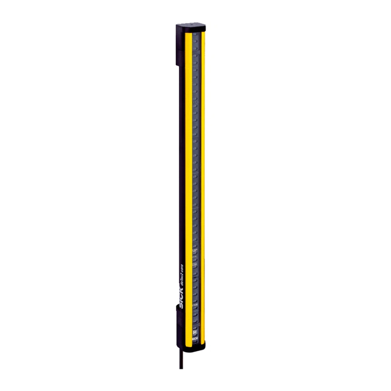
SICK deTec4 Core User manual

OPERATING INSTRUCTIONS
deTec4 Prime
Safety light curtain

Described product
deTec4 Prime
Manufacturer
SICK AG
Erwin-Sick-Str. 1
79183 Waldkirch, Germany
Germany
Legal information
This work is protected by copyright. Any rights derived from the copyright shall be
reserved for SICK AG. Reproduction of this document or parts of this document is only
permissible within the limits of the legal determination of Copyright Law. Any modifica‐
tion, expurgation or translation of this document is prohibited without the express writ‐
ten permission of SICK AG.
The trademarks stated in this document are the property of their respective owner.
© SICK AG. All rights reserved.
Original document
This document is an original document of SICK AG.
2O P E R A T I N G I N S T R U C T I O N S | deTec4 Prime 8017726/YQ03/2015-10-15 | SICK
Subject to change without notice

Contents
1 About this document........................................................................ 6
1.1 Scope......................................................................................................... 6
1.2 Target groups and structure of these operating instructions................ 6
1.3 Additional information.............................................................................. 7
1.4 Symbols and document conventions...................................................... 7
2 Safety information............................................................................ 9
2.1 General safety notes................................................................................. 9
2.2 Correct use................................................................................................ 9
2.3 Requirements for the qualification of personnel.................................... 10
3 Product description........................................................................... 12
3.1 Structure and function............................................................................. 12
3.2 Product characteristics............................................................................. 13
3.2.1 Absence of blind zones........................................................... 13
3.2.2 Automatic calibration of the protective field width................ 13
3.2.3 Beam coding............................................................................ 13
3.2.4 Alignment aid........................................................................... 13
3.2.5 Restart interlock...................................................................... 14
3.2.6 External device monitoring (EDM).......................................... 14
3.2.7 Cascading................................................................................. 14
3.2.8 System plug.............................................................................. 14
3.2.9 Flexible control cabinet cabling and status indication on
both sides................................................................................. 16
3.2.10 Status indicators...................................................................... 16
3.3 Example applications............................................................................... 19
4 Project planning................................................................................ 21
4.1 Manufacturer of the machine.................................................................. 21
4.2 Operator of the machine.......................................................................... 21
4.3 Design........................................................................................................ 21
4.3.1 Scanning range and protective field width............................. 22
4.3.2 Minimum distance from the hazardous point....................... 22
4.3.3 Minimum distance to reflective surfaces............................... 25
4.3.4 Protection against interference from systems in close prox‐
imity to each other................................................................... 26
4.4 Integration in electrical control................................................................ 28
4.4.1 Restart interlock...................................................................... 31
4.4.2 External device monitoring (EDM).......................................... 32
4.4.3 Application diagnostic output................................................. 33
4.4.4 Connection of sender and receiver........................................ 33
4.4.5 Laser alignment aid................................................................. 33
4.4.6 Cascading................................................................................. 34
4.4.7 Connection diagrams.............................................................. 37
CONTENTS
8017726/YQ03/2015-10-15 | SICK O P E R A T I N G I N S T R U C T I O N S | deTec4 Prime 3
Subject to change without notice

5 Mounting............................................................................................. 40
5.1 Safety......................................................................................................... 40
5.2 Unpacking.................................................................................................. 40
5.3 Mounting the system plug........................................................................ 41
5.4 Installation................................................................................................ 42
5.4.1 Mount the QuickFix bracket.................................................... 43
5.4.2 Mount optional FlexFix bracket............................................... 44
5.4.3 Mount optional exchange bracket.......................................... 47
5.5 Attach information label........................................................................... 49
6 Electrical installation........................................................................ 50
6.1 Safety......................................................................................................... 50
6.2 System connection (M12, 5-pin)............................................................. 51
6.3 System connection (M12, 8-pin)............................................................. 52
6.4 Extension connection (M12, 5-pin)......................................................... 53
7 Configuration..................................................................................... 54
7.1 Factory settings......................................................................................... 54
7.2 Configuration mode.................................................................................. 55
7.3 Beam coding............................................................................................. 56
7.4 Restart interlock....................................................................................... 57
7.5 External device monitoring (EDM)........................................................... 57
7.6 Application diagnostic output.................................................................. 58
7.7 Cascading.................................................................................................. 58
7.8 Status indication on both sides............................................................... 60
8 Commissioning.................................................................................. 61
8.1 Safety......................................................................................................... 61
8.2 Overview.................................................................................................... 61
8.3 Switching on.............................................................................................. 62
8.4 Align the sender and receiver.................................................................. 62
8.5 Checks....................................................................................................... 66
9 Operation............................................................................................ 67
9.1 Safety......................................................................................................... 67
9.2 Regular test rod test................................................................................. 67
9.3 LEDs........................................................................................................... 69
10 Maintenance...................................................................................... 71
10.1 safety......................................................................................................... 71
10.2 Regular cleaning....................................................................................... 71
10.3 Regular inspection.................................................................................... 72
11 Troubleshooting................................................................................. 73
11.1 Safety......................................................................................................... 73
11.2 Diagnostic LEDs........................................................................................ 73
11.2.1 Indications when switching on................................................ 73
CONTENTS
4O P E R A T I N G I N S T R U C T I O N S | deTec4 Prime 8017726/YQ03/2015-10-15 | SICK
Subject to change without notice

11.2.2 Status indication...................................................................... 75
11.2.3 Fault indicators........................................................................ 76
12 Decommissioning............................................................................. 80
12.1 Protection of the environment................................................................. 80
12.2 Disposal..................................................................................................... 80
13 Technical data.................................................................................... 81
13.1 Data sheet................................................................................................. 81
13.2 Response time.......................................................................................... 84
13.3 Power consumption.................................................................................. 85
13.4 Table of weights........................................................................................ 86
13.5 Dimensional drawings.............................................................................. 87
14 Ordering information........................................................................ 88
14.1 Scope of delivery...................................................................................... 88
14.2 Variants..................................................................................................... 88
14.3 Ordering information deTec4 Prime........................................................ 88
15 Accessories........................................................................................ 93
15.1 Brackets.................................................................................................... 93
15.2 Mounting accessories.............................................................................. 94
15.3 Weld spark guard...................................................................................... 95
15.4 Connectors................................................................................................ 96
15.5 Alignment aid............................................................................................ 99
15.6 Deflector mirrors....................................................................................... 100
15.6.1 Mounting.................................................................................. 100
15.6.2 Change in scanning range using deflector mirrors................ 100
15.6.3 Deflector mirror PNS75 - ordering information...................... 101
15.6.4 Deflector mirror PSN125 - ordering information................... 101
15.7 Mirror columns and device columns....................................................... 102
15.7.1 Mirror columns......................................................................... 102
15.7.2 Device columns........................................................................ 102
15.8 Cleaning agent.......................................................................................... 102
15.9 Test rods.................................................................................................... 102
16 Annex.................................................................................................. 103
16.1 Compliance with EU directives................................................................. 103
16.2 Checklist for initial commissioning and commissioning........................ 104
17 List of figures..................................................................................... 105
18 List of tables....................................................................................... 107
CONTENTS
8017726/YQ03/2015-10-15 | SICK O P E R A T I N G I N S T R U C T I O N S | deTec4 Prime 5
Subject to change without notice

1 About this document
These operating instructions contain information required during the life cycle of the
safety light curtain.
These operating instructions are available to all those who work with the safety light
curtain.
Please read these operating instructions carefully and make sure that you understand
the content fully before working with the safety light curtain.
1.1 Scope
These operating instructions only apply to the deTec4 Prime safety light curtain with the
following type label entry Operating Instructions: 8017724, or 8017724/YQ03.
These operating instructions are included with SICK part number 8017724/YQ03 (all
available languages).
1.2 Target groups and structure of these operating instructions
These operating instructions are intended for the following target groups: Project devel‐
opers (planners, developers, designers), installers, electricians, safety experts (e.g., CE
authorized representatives, compliance officers, persons who test and approve the
application), operators, and maintenance personnel.
The structure of these operating instructions is based on the life cycle phases of the
safety light curtain: Project planning, mounting, electrical installation, commissioning,
operation, and maintenance.
In many applications, the target groups are assigned as follows to the manufacturer
and the organization operating the machine in which the safety light curtain is inte‐
grated:
Area of responsibility Target group Special chapters of these operating instruc‐
tions 1)
Manufacturer Project developers
(planners, developers,
designers)
Project planning, page 21
Configuration, page 54
Technical data, page 81
Accessories, page 93
Installers Mounting, page 40
Electricians Electrical installation, page 50
Safety specialists Project planning, page 21
Configuration, page 54
Commissioning, page 61
Technical data, page 81
Checklist for initial commissioning and com‐
missioning, page 104
Operating company Operator Operation, page 67
Troubleshooting, page 73
Maintenance person‐
nel
Maintenance, page 71
Troubleshooting, page 73
Ordering information, page 88
1) Chapters not listed here are intended for all target groups. All target groups must take into account the
safety and warning instructions of the complete operating instructions!
In other applications, the operating organization is also the manufacturer of the equip‐
ment with the corresponding allocation of the target groups.
1 ABOUT THIS DOCUMENT
6O P E R A T I N G I N S T R U C T I O N S | deTec4 Prime 8017726/YQ03/2015-10-15 | SICK
Subject to change without notice

1.3 Additional information
www.sick.com
The following information is available on the Internet:
•versions in other languages
•data sheets and application examples
•CAD data of drawings and dimensional drawings
•certificates (e.g. EU declaration of conformity)
•Guide for Safe Machinery (Six steps to a safe machine)
1.4 Symbols and document conventions
In this document, the following symbols and conventions are used:
Safety notes and other notes
In this document, the following types of safety notes and other notes are used:
DANGER
Indicates a situation presenting imminent danger, which will lead to a fatality or serious
injuries if not prevented.
WARNING
Indicates a potentially dangerous situation, which may lead to a fatality or serious inju‐
ries if not prevented.
CAUTION
Indicates a potentially dangerous situation, which may lead to moderately severe or
minor injuries if not prevented.
NOTICE
Indicates a potentially dangerous situation, which may lead to material damage if not
prevented.
NOTE
Indicates useful tips and advice.
Instructions to action
bThe arrow denotes instructions to action. Read carefully and follow the instructions
for action.
1. The sequence of instructions for action is numbered.
2. Read carefully and follow the instructions for action in the order stated.
LED symbols
These symbols indicate the status of an LED:
The LED is off.
The LED is flashing.
The LED is illuminated continuously.
Sender and receiver
These symbols indicate the sender and receiver of the safety light curtain:
ABOUT THIS DOCUMENT 1
8017726/YQ03/2015-10-15 | SICK O P E R A T I N G I N S T R U C T I O N S | deTec4 Prime 7
Subject to change without notice

The symbol indicates the sender.
The symbol indicates the receiver.
1 ABOUT THIS DOCUMENT
8O P E R A T I N G I N S T R U C T I O N S | deTec4 Prime 8017726/YQ03/2015-10-15 | SICK
Subject to change without notice

2 Safety information
This chapter contains information on general safety for the safety light curtain.
More safety information about specific usage situations of the safety light curtain is
available in the respective chapters.
2.1 General safety notes
DANGER
Hazard due to lack of effectiveness of the protective device
In the case of non-compliance, it is possible that the dangerous state of the machine
may not be stopped or not stopped in a timely manner.
bPlease read this document carefully and make sure that you understand the con‐
tent fully before working with the device.
bPay particular attention to all warnings in this document.
CAUTION
Class 1 laser
LASER
1
Figure 1: Class 1 laser
This device has been classified in accordance with the following standards:
•IEC 60825-1:2007/EN 60825-1:2007
•IEC 60825-1:2014/EN 60825-1:2014
•21 CFR 1040.10 and 1040.11, except for deviations pursuant to Laser Notice
No. 50 dated 2007-06-24
The laser is eye-safe. Looking directly into the laser may cause temporary impairments.
The outlet opening of the laser radiation is located in the sender, see figure 3,
page 17. The laser is only active when the laser alignment aid is switched on.
Laser identification is located on the rear of the sender.
bComply with the latest version of the applicable provisions on laser protection.
CAUTION
If any operating or adjusting devices other than those specified in this document are
used or other methods are employed, this can lead to dangerous exposure to radiation.
bOnly use the operating or adjusting devices specified in this document.
bOnly follow the methods specified in this document.
bDo not open the housing, except for the purposes of the installation and mainte‐
nance work specified in these operating instructions.
2.2 Correct use
The deTec4 Prime safety light curtain is an electro-sensitive protective device (ESPE)
and is suitable for the following applications:
SAFETY INFORMATION 2
8017726/YQ03/2015-10-15 | SICK O P E R A T I N G I N S T R U C T I O N S | deTec4 Prime 9
Subject to change without notice

•Hazardous point protection
•Access protection
•Hazardous area protection
The deTec4 Prime safety light curtain must only be used within the limits of the prescri‐
bed and specified technical data and operating conditions at all times.
Any instance of improper use, incorrect modification, or manipulation of the
deTec4 Prime safety light curtain shall void any warranty provided by SICK AG; further‐
more, SICK AG shall not accept any responsibility or liability for any resulting damage
and consequential damage.
Foreseeable misuse
DANGER
Hazard due to lack of effectiveness of the protective device
Persons and parts of the body to be protected may not be recognized in case of non-
observance.
The safety light curtain works as an indirect protective measure and cannot provide pro‐
tection from parts thrown out nor from emitted radiation. Transparent objects are not
detected.
bOnly use the safety light curtain as an indirect protective measure.
Among others, the deTec4 Prime safety light curtain is not suitable for the following
applications:
•Outdoors
•Under water
•In explosive environments
•At altitudes over 3,000 m above sea level
•In environments with enhanced ionizing radiation
2.3 Requirements for the qualification of personnel
The safety light curtain must be configured, installed, connected, commissioned and
serviced only by qualified safety personnel.
Project planning
For project planning, a person is considered competent when he/she has expertise and
experience in the selection and use of protective devices on machines and is familiar
with the relevant technical rules and national work safety regulations.
Mechanical mounting
For mechanical mounting, a person is considered competent when he/she has the
expertise and experience in the relevant field and is sufficiently familiar with the appli‐
cation of the protective device on the machine that he/she can assess its operational
safety status.
Electrical installation
For electrical installation, a person is considered competent when he/she has the
expertise and experience in the relevant field and is sufficiently familiar with the appli‐
cation of the protective device on the machine that he/she can assess its operational
safety status.
2 SAFETY INFORMATION
10 O P E R A T I N G I N S T R U C T I O N S | deTec4 Prime 8017726/YQ03/2015-10-15 | SICK
Subject to change without notice

Configuration
For configuration, a person is considered competent when he/she has the expertise
and experience in the relevant field and is sufficiently familiar with the application of
the protective device on the machine that he/she can assess its work safety aspects.
Commissioning
For commissioning, a person is considered competent when he/she has the expertise
and experience in the relevant field and is sufficiently familiar with the application of
the protective device on the machine that he/she can assess its operational safety sta‐
tus.
Operation and maintenance
For operation and maintenance, a person is considered competent when he/she has
the expertise and experience in the relevant field and is sufficiently familiar with the
application of the protective device on the machine and has been instructed by the
machine operator in its operation.
An operator must clean the safety light curtain and carry out specific checks as
instructed. Additional information for the operator of the machine: see "Operation",
page 67 and see "Regular cleaning", page 71.
SAFETY INFORMATION 2
8017726/YQ03/2015-10-15 | SICK O P E R A T I N G I N S T R U C T I O N S | deTec4 Prime 11
Subject to change without notice

3 Product description
This chapter provides information on the operation of the safety light curtain and shows
examples of its range of use.
3.1 Structure and function
The deTec4 Prime safety light curtain is an electro-sensitive protective device (ESPE)
consisting of a sender and receiver.
A series of parallel infrared light beams form a protective field between sender and
receiver that protects the hazardous area (hazardous point, access, and hazardous
area protection). When one or more beams are completely interrupted, the safety light
curtain reports the interruption in the light path to the secure output signal switching
devices (OSSDs) by a signal change. The machine or its control must evaluate the sig‐
nals reliably (e.g., by means of a safety controller or a safety relay) and bring an end to
the dangerous state.
Sender and receiver automatically synchronize themselves optically. An electrical con‐
nection between both components is not required, but is advantageous (see "Flexible
control cabinet cabling and status indication on both sides", page 16).
Figure 2: Sender and receiver
Protective field height
The protective field height indicates the range within which the test rod belonging to the
safety light curtain is reliably detected. The size of the safety light curtain determines
the protective field height.
3 PRODUCT DESCRIPTION
12 O P E R A T I N G I N S T R U C T I O N S | deTec4 Prime 8017726/YQ03/2015-10-15 | SICK
Subject to change without notice

Protective field width
The protective field width is the dimension of the light path between sender and
receiver. The maximum protective field width is limited by the scanning range.
Resolution
The resolution describes the size of the smallest object detected by the safety light cur‐
tain in the protective field. The resolution corresponds to the diameter of the test rod
belonging to the safety light curtain, which is reliably detected when in the protective
field.
With the appropriate resolution, the safety light curtain provides finger and hand protec‐
tion.
Information on protective field height, protective field width, and resolution: see "Data
sheet", page 81.
Scanning range
The scanning range is the maximum protective field width. It is subject to the resolution
variant (14 mm or 30 mm).
Information on protective field height, protective field width, and resolution: see "Data
sheet", page 81.
The scanning range is reduced by using deflector mirrors and/or a weld spark guard,
see "Deflector mirrors", page 100, see "Weld spark guard", page 95.
3.2 Product characteristics
3.2.1 Absence of blind zones
The design and construction of the safety light curtain extends the protective function
of a device to the end of the housing without any blind spots. The absence of blind
zones reduces the space requirement when integrated in the machine.
3.2.2 Automatic calibration of the protective field width
When switched on, the safety light curtain automatically calibrates to the protective
field width.
3.2.3 Beam coding
Depending on its configuration, the safety light curtain operates with one of three beam
codings: uncoded, code 1 or code 2. The beam coding “uncoded” allows for particularly
short response times. In order to avoid mutual interference between two neighboring
safety light curtains, one can be operated with code 1 and the other with code 2.
3.2.4 Alignment aid
A laser alignment aid is installed in the sender of the safety light curtain. The laser
alignment aid can be switched on to perform a simple alignment of the sender.
Alignment quality LEDs are installed in the receiver of the safety light curtain. To per‐
form a simple alignment of the receiver, the alignment quality LEDs indicate the align‐
ment quality once the safety light curtain has been switched on.
PRODUCT DESCRIPTION 3
8017726/YQ03/2015-10-15 | SICK O P E R A T I N G I N S T R U C T I O N S | deTec4 Prime 13
Subject to change without notice

3.2.5 Restart interlock
The safety light curtain has an integrated restart interlock. The function can be config‐
ured during commissioning.
A restart interlock prevents the machine from starting again once the protective device
has been triggered. The operator must first press a reset pushbutton to allow the pro‐
tective device to resume its monitoring function. The operator can then restart the
machine.
The reset pushbutton can be connected locally to the extension connection or in the
control cabinet.
3.2.6 External device monitoring (EDM)
The safety light curtain has integrated external device monitoring. The function can be
configured during commissioning.
External device monitoring monitors the status of the downstream contactors.
A requirement for the use of external device monitoring is that positively guided contac‐
tors are used to switch off the machine. If the auxiliary contacts of the positively guided
contactors are connected to external device monitoring, external device monitoring
checks whether the contactors drop out when the OSSDs are switched off.
3.2.7 Cascading
With cascading, up to three safety light curtains are connected in series, e.g., to provide
reliable presence detection. The device connected to the control cabinet is the host
device. The subsequent sensors are called guest 1 and guest 2.
3.2.8 System plug
The safety light curtain requires a system plug. The system plug is available in a range
of variants.
Depending on the variant, there are one or two M12 plug connectors on the system
plug:
•System plug with 5-pin system connection
•System plug with 8-pin system connection
•System plug with 5-pin system connection and 5-pin extension connection
•System plug with 8-pin system connection and 5-pin extension connection
System plug and functions of the safety light curtain
The following functions are available depending on the system plug used:
•Restart interlock
•External device monitoring (EDM)
•Application diagnostic output
•Cascading
Restart interlock
•Requirement for the receiver: 8-pin system connection or extension connection.
•Additional information see "Restart interlock", page 31.
External device monitoring (EDM)
•Requirement for the receiver: 8-pin system connection or extension connection.
•Additional information see "External device monitoring (EDM)", page 32.
Application diagnostic output
3 PRODUCT DESCRIPTION
14 O P E R A T I N G I N S T R U C T I O N S | deTec4 Prime 8017726/YQ03/2015-10-15 | SICK
Subject to change without notice

•Requirement for the receiver: 8-pin system connection or extension connection.
•When the restart interlock is configured, the application diagnostic output located
on the same plug connector as the reset pushbutton signals when the reset push‐
button needs to be pressed.
•Otherwise, the application diagnostic output signals that the receiver is receiving a
weak signal from the sender, e.g., because the sender and receiver are not cor‐
rectly aligned or because the front screen is contaminated.
Cascading
•Requirements: extension connection at the host, 5-pin system connection at the
guest devices.
•Additional requirement for cascades with two guest devices: extension connection
at the first guest.
•Restart interlock, external device monitoring (EDM), and application diagnostic
output are possible if one of the following requirements is met:
°8-pin system connection at the host receiver.
°Extension connection at the last guest receiver of the cascade.
•Additional information: see "Cascading", page 34.
Using the system plugs
System plug with 5-pin system connection
•Single device without additional function
•Last guest of a cascade, no additional function on the device
System plug with 8-pin system connection
•Single device with restart interlock, external device monitoring (EDM), or applica‐
tion diagnostic output at the system connection
System plug with 5-pin system connection and extension connection
•Host of a cascade, no additional function on the device
•First guest of a cascade with two guest devices, no additional function on the
device
•Receivers only: single device with restart interlock, external device monitoring
(EDM), or application diagnostic output at the extension connection
•Receivers only: last guest of a cascade, restart interlock, external device monitor‐
ing (EDM), or application diagnostic output at the extension connection
•If a sender does not have an additional guest connected to it, the extension con‐
nection has no function and must be sealed with a protective cap.
System plug with 8-pin system connection and extension connection
•Host of a cascade, restart interlock, external device monitoring (EDM), or applica‐
tion diagnostic output at the system connection
•Receivers only: single device with restart interlock, external device monitoring
(EDM), or application diagnostic output
•If a sender does not have an additional guest connected to it, the extension con‐
nection has no function and must be sealed with a protective cap.
PRODUCT DESCRIPTION 3
8017726/YQ03/2015-10-15 | SICK O P E R A T I N G I N S T R U C T I O N S | deTec4 Prime 15
Subject to change without notice

System plug type code
1000 1200 1100 1300
Single system Sender
1) 2) 1) 2)
Receive
r
Host Sender
––
1)
Receive
r
First guest (for
cascade with
two guest devi‐
ces)
Sender
–––
Receive
r
Last guest Sender
–
2)
–
Receive
r
Table 1: Using the system plugs
1) At the sender, the 8-pin system connection is solely for the purposes of providing standardized wiring. It is
particularly recommended if the 8-pin system connection at the receiver is used and the sender and
receiver are connected to each other via a T-piece.
2) If a sender does not have an additional guest connected to it, the extension connection has no function
and must be sealed with a protective cap.
–System plug not suitable.
System plug suitable. No additional function on the device.
System plug suitable. Restart interlock, external device monitoring (EDM), or application
diagnostic output available at this system plug.
3.2.9 Flexible control cabinet cabling and status indication on both sides
The safety light curtain can be connected to the control cabinet in different ways as
required:
•Separate connecting cables for sender and receiver
•Separate connecting cables for sender and receiver with connection in the control
cabinet
•Connection of sender and receiver via a T-piece, shared 5-pin or 8-pin connecting
cable to the control cabinet
In a cascade, only the host sender and host receiver are connected to the control cabi‐
net.
The OSSD status and the status of the protective field are indicated at the sender and
receiver via LEDs when the sender and receiver are connected in the control cabinet or
via a T-piece. If the sender and receiver are not connected to each other, this status
information is only indicated at the receiver.
3.2.10 Status indicators
The sender and receiver LEDs indicate the operating status of the safety light curtain.
3 PRODUCT DESCRIPTION
16 O P E R A T I N G I N S T R U C T I O N S | deTec4 Prime 8017726/YQ03/2015-10-15 | SICK
Subject to change without notice

Sender indicators
14 mm 30 mm
2
1
3
Figure 3: Sender indicators
The sender has a laser alignment aid and at least two LEDs, which indicate the opera‐
tional status:
No. LED color Function Labeling
1 Red/yellow/green Field indicator 1) –
2 – Laser alignment aid –
3 Red/yellow/green Status indication STATE
1) Safety light curtains with protective field height > 300 mm have several LEDs for the field indicator.
Complete overview of the LED statuses and their meanings: see "Diagnostic LEDs",
page 73.
PRODUCT DESCRIPTION 3
8017726/YQ03/2015-10-15 | SICK O P E R A T I N G I N S T R U C T I O N S | deTec4 Prime 17
Subject to change without notice

Receiver indicators
14 mm 30 mm
2
1
3
Figure 4: Receiver indicators
The receiver has at least six LEDs, which indicate the operational status:
No. LED color Function Labeling
1 Red/yellow/green Field indicator 1) –
2 Blue Alignment quality 1/E, 2, 3, 4/R
3 Red/green OSSD status OSSD
1) Safety light curtains with protective field height > 300 mm have several LEDs for the field indicator.
The blue alignment quality LEDs in combination with the red flashing field indicator also
denote fault indications.
Complete overview of the LED statuses and their meanings: see "Diagnostic LEDs",
page 73.
3 PRODUCT DESCRIPTION
18 O P E R A T I N G I N S T R U C T I O N S | deTec4 Prime 8017726/YQ03/2015-10-15 | SICK
Subject to change without notice

3.3 Example applications
Figure 5: Hazardous point protection
Figure 6: Access protection
PRODUCT DESCRIPTION 3
8017726/YQ03/2015-10-15 | SICK O P E R A T I N G I N S T R U C T I O N S | deTec4 Prime 19
Subject to change without notice

Figure 7: Hazardous area protection
Figure 8: Access protection with presence detection, implemented by cascade
3 PRODUCT DESCRIPTION
20 O P E R A T I N G I N S T R U C T I O N S | deTec4 Prime 8017726/YQ03/2015-10-15 | SICK
Subject to change without notice
Other manuals for deTec4 Core
16
Table of contents
Other SICK Protection Device manuals
Popular Protection Device manuals by other brands

ABB
ABB RED615 ANSI Applications manual
Clippasafe
Clippasafe DVD & DigiBox Protector instruction manual

Fall Guardian
Fall Guardian 3000 Installation and use instructions

aidapt
aidapt VA116S Usage and maintenance instructions
Franklin
Franklin PUMPTEC-PLUS Installation and operating guide
IPC
IPC Turbo Sleuth instruction manual
