14. SOURCE SWITCH
When the MIX-B SOURCE switch is up,MIX-B receives its input from the FLIP switch .Remember,the FLIP
switch alternates MIC/LINE or TAPE to channel strip and to MIX-B.
- With TAPE as an input (SOURCE up to select the FLIP switch and MIC/LINE or TAPE switch in the up
position),the MIX-B section functions as a tape monitor sub-mix, allowing you to listen to the inputs and outputs
of your multi-track record as you record.This is the most common use of the MIX-B section, during tracking and
overdubbing.
- With MIX/LINE as an input (SOURCE up to select the FLIP switch, and MIX/LINE or TAPE switch in the
down position), MIX-B becomes an additional input to add tracks or effects during a mix-down.
- With CHANNEL as an input (SOURCE down in CHANNEL position),MIX-B taps its signal from the channel
fader.
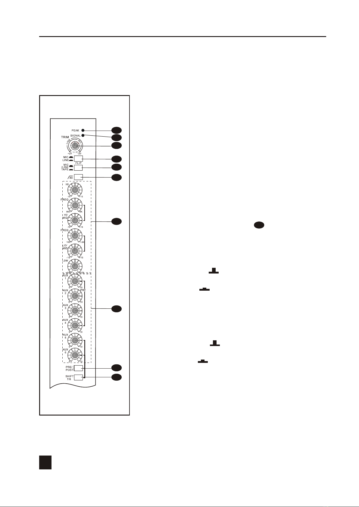
15. PAN CONTROL
This control adjusts the stereo position of the signal between the stereo L/R buses,and also between odd and even
pairs of Buses 1 through 8.
This control allows you to place the channel's input signal within the stereo image by assigning more or less of
the signal to the left or right sub-master controls.
Turning the Pan control to the left (odd/L)of center moves the apparent source toward the left channel and Group
1,3,5,7 buses, turning it to the right moves the source toward the right channel and Group 2,4,6,8 buses.
16. CHANNE MUTE SWITCH
When this switch is off, the signal of each channel will be the MAIN MIX L/R buses ,the Group 1~8 buses and
AUX 1~8 buses.
When this switch is on , the output signal to each bus muted completely. This switch should be turned on for
unused channels.The channel's mute switch does not affect the channel's insert output or direct output.
17. BUS ASSIGH SWITCH
When these switchs are engaged, the channel's input signal can be routed to the 8 group busses.
In conjunction with selecting the group routing, the position of the channel's pan control determines if a signal is
routed to Group 1 or 2, 3 or 4, 5 or 6, Group 7 or 8 and/or Mix L or If the pan control is panned left, it will be
routed Group 1,3,5,7 and / or Mix L ; if the pan control is panned right, the signal will appear at Group 2, 4, 6,8
and/or Mix R.
18. CHANNEL FADER
The 100-mm audio taper fader controls the output level of channel that is fed to Mix master and Sub Group
master.
The channel fader should optimally be set near the"o"level when all other controls are set to their normal settings.
19. SOLO SWITCH
The channel SOLO switch assigns the output of channel PAN control to the stereo solo buses . SOLO does not
interrupt ,the eight sub-master , the L/R Mix OUT or AUX sends, and can be used at any time without affecting
the recording process.
SOLO is handy for spot-checking the presence and quality of individual input while setting up , recording and
mixing. The channel SOLO function is normally post fader/post mute.
5
8 BUS MIXING CONSOLE
7