DARAY BILITE Specification sheet

®
BILITE
UNIT, CEILING AND
WALL MOUNTED
OPERATING AND
INSTALLATION MANUAL
QAM.BILITE.0811.7


3
INSTALLATION
1.
GENERAL DESCRIPTION
4
2.
SPECIFICATION
4
2.1 Serial numbers and labelling
4
2.2 Dimensions 5,6
3.
OPERATION
7
4.
MAINTENANCE, CLEANING AND DISINFECTION
8
4.1 Troubleshooting
8
4.2 Routine maintenance
9
5. LAMP-BAR REPLACEMENT 10
6.
ADJUSTMENT OF ARM BALANCE TO ELIMINATE DRIFT
11
7.
INSTALLATION
12
7.1 Unit/chair mount with remote transformer
12
7.2 Ceiling mount 13
7.3
Wall mount
19
7.4
Installation - Fit the jib-joint cover
21
7.5 Fitting the light head
22
RETURNS POLICY 24
WARRANTY
25
WARRANTY REGISTRATION
26
Tel: 0844 375 9000 Fax: 0333 321 0973
®

4
info@daray.com • www.daray.com

5
1. GENERAL DESCRIPTION
DARAY’s Bilite is the world-renowned dental operating light which employs twin-beam
technology to eliminate shadows in the oral cavity. The light produces a wide, virtually
cold, rectangular light patch with extremely sharp edges.
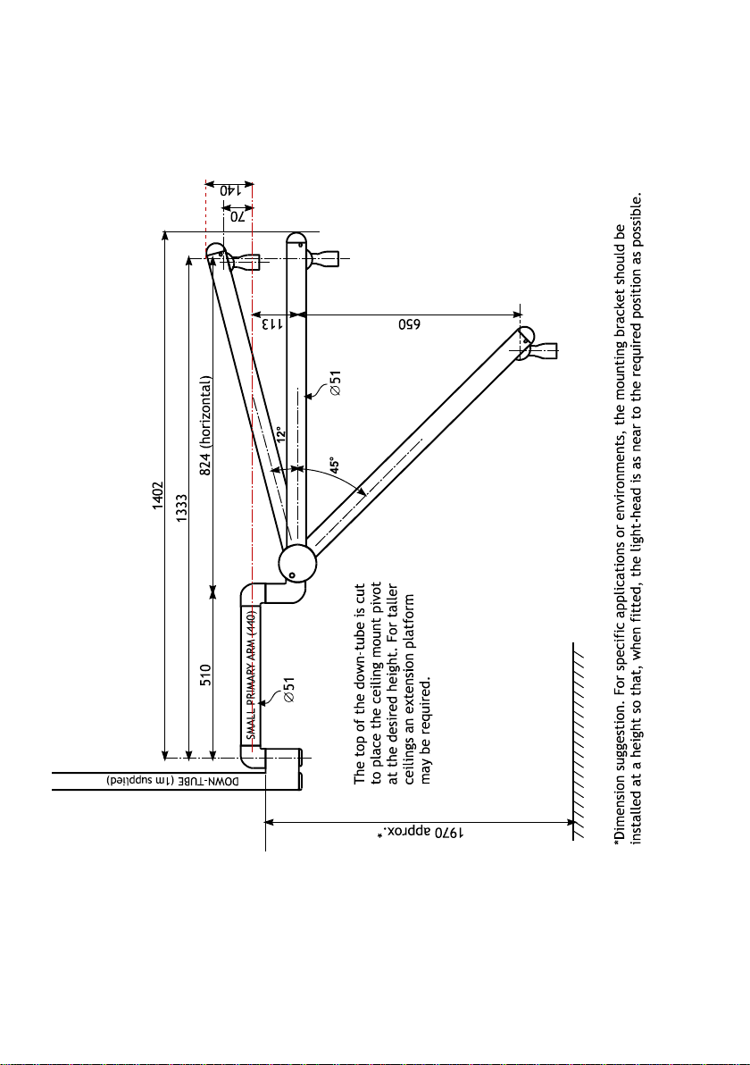
The light head is mounted on DARAY’s sophisticated balanced suspension arm which is light
to move and does not drift once positioned. The Bilite features variable-intensity control on
the wall and ceiling-mounted models, and all versions operate from a safe, low voltage fed
through the suspension arm to the light head.
DARAY’s extremely quick and simple lamp-bar change is retained, allowing blown bulbs to
be swapped quickly without risk of burnt fingers.
The ceiling or wall light comprises 4 parts: a mounting, a variable-intensity power-supply
module, a suspension arm, and the light head. The power-supply module is fitted with an
IEC inlet so the mains may be supplied via a plug-in flex from a standard mains socket. This
arrangement can readily be converted using a parts kit supplied as standard for use where
the mains-electrical supply cables are ‘chased’ into a wall. The power-supply module is
fastened to the wall-mount bracket for the BLLW and can be screwed to the wall to power
the BLLC.
The unit-mounted BLL comes with the light head, suspension arm and separate transformer
for mounting with the chair-package utilities.
2. SPECIFICATION
Light intensity at 0.7m 0 - 26,000 lux
Colour temperature 3,600K
Patch size at 0.7m 300 x 200 mm
Operating voltage
12V AC
Input voltage
230V 50Hz, class 1 (earthed)
Arm reach 1650mm
Jib arm vertical movement +15° to -45°
Bulb
12V 55W DARAY’s part no: LB1024
2.1 Serial numbers and labelling
Each Bilite is allocated a unique serial number located on the inside of the slip-ring housing,
and is identified by a label affixed to the power-supply module.

6
2.2 Dimensions (1/2)

7

8
Dimensions (2/2)

9
3. OPERATION
0
I
®
D14560
TM
WWW.DARAY.COM
0870 777 2664
Wall mount PSU module
Wall mount
Turn on the mains rocker switch on the power-supply module. The switch should illuminate.
If the switch does not illuminate, check the mains supply and then the fuses in the module,
which are located on its right-hand side. For the versions powered via an IEC lead with a
moulded mains plug, check the fuse in the mains plug.
Turn on the light using the switch on the head mounting. Set the required illumination level
using the variable intensity control on the power-supply module.
Ceiling mount
Switch on at the switch fused spur. The indicator on the switch fused spur should illuminate.
Turn on the light using the switch on the head mounting. Set the required illumination level
using the variable intensity control module.
If the Bilite does not illuminate, press the variable intensity control knob and then set the
desired intensity.
All models
After use, switch off the power-supply module on the wall, as well as the light-head switch.
Use the handles to steer the light-patch to where you want it; the suspension arm swivels at
the mounting and at the joint between the primary and jib arms. The jib arm allows the
light-head to be moved up and down. The light-head itself can rotate 360° on the jib arm in
its horizontal axis.
Mains rocker switch
Variable intensity
control

10
4. MAINTENANCE, CLEANING AND DISINFECTION
WARNING! Do not use strong chemical cleaning agents such as ‘Dettox’ to sterilise
the light.
Do not use any abrasive materials to clean the light.
CAUTION! The light is not waterproof, so do not use excessive cleaning fluid amounts.
Suitably protect hands.
Wipe the light using clean tissue or soft towelling - pay special attention to the switch
and handles.
Apply to all surfaces a 1% solution of sodium hypochlorite using a soft cloth.
Within 10 minutes, remove the chemical from all surfaces using a damp, soft cloth.
The chemical will cause corrosion of metal parts, if it is not thoroughly removed.
Apply Isopranol to the surfaces – this is an alcohol-based fluid which evaporates without
leaving any residue and can be obtained as an impregnated-cloth applicator.
4.1 Troubleshooting
If the light does not illuminate, change the lamp-bar – see Section 5, below.
If the light still does not illuminate, further investigation should only be undertaken by a
qualified electrician.

11
4.2 Routine maintenance
The Bilite is designed and manufactured to stringent quality standards. Observing the
following procedures will help to maintain the light’s optimum performance.
Light-head
Operation
Suggested Interval
Method
Clean all exterior surfaces
As required
Disinfecting and cleaning directions -
see section 4.
Arm
Operation Suggested Interval Method
Lubricate wall-mount plate bush Six Monthly
On wall-mounted units, lift the arm so
its spigot is almost clear of the bush in
the wall-mount plate and re-lubricate if
required.
Lubricate ceiling mount spigot
Six Monthly
On ceiling mount units, support the arm
and remove the 3 screws retaining the
fitting adaptor into the down-tube.
Lower the arm until the adaptor and
key can be removed. Slide sleeve up
and inspect for lubrication. Re-lubricate
spigot and sleeve if required.
Reassemble.
Check tightness of all five
fixing screws.
One month after
installation and then
annually.
Check balance of jib over
whole range.
See section 6.
Ceiling Mount
Operation
Suggested Interval
Method
Inspect 6 button head socket
screws for tightness and check that
washers are fitted under head.
Six Monthly
Tighten with appropriate hex key
Check that down-tube is rigidly
mounted to the ceiling (do not
exert undue force).
Annually
If any movement found – immediately
advise your service dealer.
Wall Mount
Operation
Suggested Interval
Method
Check security of wall fixing
Annually
Investigate any movement – ensure your
building contractor is consulted if
movement is found.

12
5. LAMP-BAR REPLACEMENT
In the event of lamp failure, switch off the unit, and remove the front fascia by easing the
lugs at each end. The lamp-bar may then be withdrawn from the case.
CAUTION: the lamp will be very hot if the light has been recently used.
Being careful not to touch the bulb itself, fit a new lamp-bar by engaging its 2 prongs into
the guide holes and pushing evenly home. Remember to order spare lamp-bars; LB1024.

13
6. ADJUSTMENT OF ARM BALANCE TO ELIMINATE DRIFT
Insert a small implement (e.g. hex wrench 2mm AF) into one of the holes and turn capstan
in the direction of Arrow A until desired balance is obtained.
Note: To eliminate rise in the jib at the fully down position turn the capstan in the opposite
direction to Arrow A.
To assist in making this adjustment, it may be necessary to remove the arm joint cover:
Remove the 2 snap in plugs and the 2 screws, allowing the cover half mouldings to be
separated and the moving cover to slide down the jib arm. This provides better access to
the slot through which the capstan nut is adjusted.
Note: When re-assembling, ensure that the moving cover is correctly positioned with
the ‘T’ notation on the component at the ‘Top’.
Holes
A

14
7. INSTALLATION
CAUTION: this product must be earthed.
7.1 Unit/chair mount with remote transformer
Mount the transformer in a suitable position under the chair.
Ensure that the transformer and electrical connections are sited so that they do not come
into contact with liquid.
The transformer low voltage cable terminates in a Molex plug. The transformer is supplied
with a low voltage cable which has suitable Molex adaptors at either end – one which will
connect to the transformer only, the other to the Molex adaptor on the low voltage cable
supply of the arm assembly.
Feed the low voltage cable through the support post and any umbilical to the transformer
site. Make sure there are no sharp bends or possible contact with surfaces which may rub or
cut the cable.
Remote
transformer
Low voltage cable
Support post
Bilite arm
Ensure the post mount is truly vertical. Connect the low voltage cable to the arm assembly.
Fit the arm to the post and connect the low voltage lead to the transformer.
Fit the light-head (see section 8)

15
7.2 Ceiling mount
Check you have the following items:
Ceiling-mount plate assembly and cover
Down-tube
Down-tube grub-screw
Down-tube spigot nylon washer
Down-tube bungs
Suspension arm
Light head
Grease sachet
Power supply module
Determine where to mount the light.
WARNING: please note that this information is provided for guidance only and that a
qualified builder or structural engineer should be consulted if you have any doubt about
the suitability of the proposed mounting position.
WARNING: the light-head operates from a low-voltage supply produced by a transformer
in the ceiling mount assembly and fed through the suspension arm. On NO ACCOUNT
should the arm be connected directly to mains voltages.

16
Fitting the ceiling plate
Remove the clamp bolts, safety bolt/nylon insert nut and the clamp. Keep these
parts in a safe place for use later.
Fix the plate to the ceiling with bolts, screws or studs and nuts through the centre of each
jack bolt. Do not fully tighten the fasteners at this point.
Note: The nuts thread-locked to the upper end of the 3 jack bolts act as pressure pads.
These pressure pads must be seated firmly against the mounting surface.
The jack bolts can then be used to adjust the position of the ceiling plate and down-
tube.

17
Fitting the Down-tube
A 1 metre length of down-tube is included with all ceiling mount kits, and must be securely
fitted in accordance with these instructions.
The down-tube should be cut to length on-site to suit the particular ceiling height and
application.
Note when installed the down-tube must leave clearance above the ceiling mount plate to
prevent the cable being trapped.
For determining the cut point, we suggest measuring the distance between the ceiling
mounting plate, and a point about 1900mm above the floor.
The length of the down-tube should be altered to suit the room dimensions and the
particular application for which the light is to be used.
De-burr as necessary.
NOTE: For suspended ceilings, the ceiling hole trim and retaining band should be placed
over the downtube BEFORE proceeding.
Loosely refit the clamp and clamp
bolts. Fit the down-tube in the clamp
and tighten the clamp bolts to firmly
hold it in place. Drill a 6mm hole
completely through the tube via the
guide holes in the clamp and fit the
safety bolt and nylon insert lock nut
supplied.
NOTE: TO ENSURE THE USER'S
SAFETY, THE SAFETY BOLT AND
NYLON INSERT LOCK NUT MUST BE
FITTED PROPERLY
Feed the end of the low-voltage
cable assembly through the tube.
Tighten both clamp screws fully and evenly until the tube is firmly clamped.
Adjust the 3 large bolts such that the down-tube is absolutely vertical. Tighten the fixing
bolts or screws to firmly clamp the jack bolts tight against the joist, tighten the thin
locknuts and re-check that the down-tube remains vertical, and the mounting plate has no
movement. If necessary, repeat the adjustment.
Run the low-voltage cable to the mounted power-supply module, feed it through the
grommet on the top of the module and connect it to the 2-way terminal block wired to the
low-voltage output from the transformer.
Refit the module to its mounted rear plate.

18
NOTE: For suspended ceilingscut a clearance hole in a ceiling tile, replace the tile and
slide the trim up the downtube until it is firmly against ceiling tile, then roll the trim
retaining band upward until it holds the trim in position.
NOTE: For conventional ceilings fit the cover, holding it in place with the retaining band
from the fitting kit.
Install the primary arm
To ensure the smooth rotation of the arm, it is essential that the primary arm spigot is
lightly lubricated before assembly.
A sachet of silicon grease is provided.
Place the nylon washer over the primary arm spigot.
Insert the primary arm spigot into the down-tube.
Down-tube
Arm assembly
Nylon washer
Connector
Primary arm spigot
Down-tube
Suspended ceiling trim
Trim retaining band

19
Join the connector from the primary arm to the connector from the down-tube.
Fit the supplied bungs.
Make sure to sit the joined connectors inside the bung before fitting to prevent the
cable from being damaged.
Fit the jib-joint cover (see p.20).
Fit the light-head (see p.21).
Check everything for tightness and safety.
Check the arm and head for freedom of movement.
Rebalance the jib arm if necessary (see p.11).
LUBRICATE

20
Table of contents
Other DARAY Lighting Equipment manuals
Popular Lighting Equipment manuals by other brands

Osram
Osram 660 user manual

STL
STL Rear Raptor Series Operation manual and instructions

Vision & Control
Vision & Control LDLF60x480-G525/24V Instructions for use

ViSAGE
ViSAGE VIS0495.2 user manual

STL
STL K-FORCE TOW 65 instruction manual

Hubbell
Hubbell Dual Lite EV Series Installation, operation and service instructions