DARAY X340 Manual

X340
LED Examination Light
Operating & Installation Manual
QAM.X340.0519.9

Page 1of 43

Page 2of 43
Table of Contents
1. Introduction................................................................. 4
1.1 Supported Lights ....................................................... 5
2. Technical Specifications .................................................. 6
2.1 Pre-Installation Responsibilities and component packing list ... 7
2.2 Pre-Start Checks ....................................................... 8
3. Operation ................................................................... 9
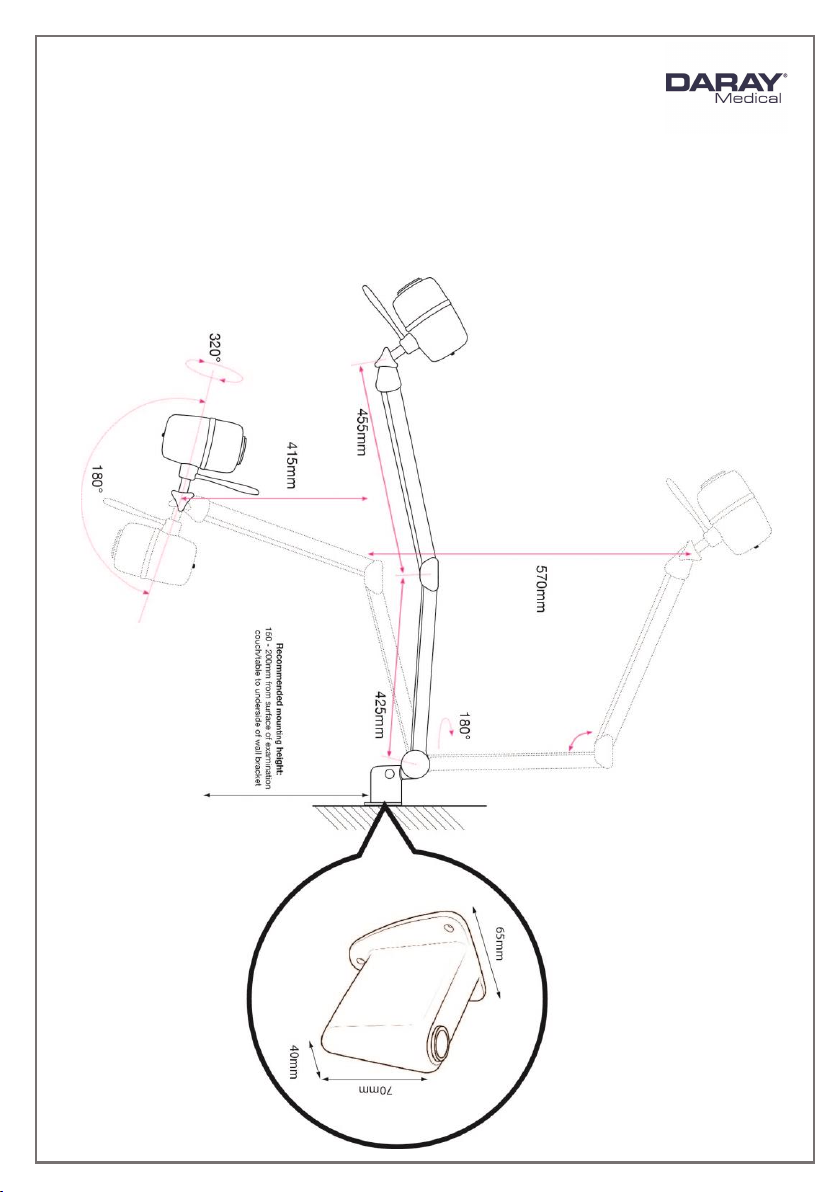
3.1 Range of Motion ........................................................ 9
3.2 Powering On & Variable Intensity ..................................12
3.3 Adjusting the Light Head ............................................13
3.4 Operating the Downtube.............................................14
4. Installation .................................................................15
4.1 Wall mounted versions ...............................................15
4.1.1 Considerations....................................................16
4.1.2 X340LW - Placement and Installation .........................17
4.1.3 X340LE1 –Placement and Installation ........................19
4.1.4 X340LE2 –Placement and Installation ........................19
4.1.5 X340LE3 –Placement and Installation ........................20
4.1.6 X340LE4 - Placement and Installation ........................20
4.2 Rail mounted version (X340LR) .....................................22
4.3 Desk mounted versions (X340LD / X340LDS / X340LFDM) .......22
4.4 Mobile version (X340LM) .............................................23
4.5 Optional battery back-up ............................................25
4.6 Ceiling Mounted version (X340LC) ..................................26
4.6.1 Considerations....................................................26
4.6.2 Attachment methods and void suspension ...................27

Page 3of 43
4.6.3 Lighting configuration...........................................28
4.6.4 Affixing the Ceiling plate .......................................28
4.6.5 Wiring and transformer layout.................................29
4.6.6 Downtube adjustment and installation .......................30
4.6.7 Light head and arm fixing ......................................33
5. Maintenance ...............................................................34
5.1 Maintenance schedule................................................34
5.2 Safety Precautions ....................................................34
5.3 Product Cleaning & Care Guidelines ...............................35
5.4 Detaching Parts .......................................................36
5.5 Fuses and their replacement........................................36
5.6 Rigid Arm Adjustments...............................................37
6. Troubleshooting Guide & Spare Parts ..................................38
7. Warranty Information ....................................................40
7.1 Returns Policy .........................................................40
7.2 Warranty Details ......................................................41

Page 4of 43
1. Introduction
DARAY’s X340 is a state-of-the art, cost-effective examination light for use during
medical or veterinary consultation and diagnosis. The light uses the latest LED
technology to give an intense light at the ideal colour temperature for accurate
medical diagnosis (without the need for secondary filtering) with virtually no heat.
Multiple mounting options are available.
The X340 features a high-output intensity controlled by a button on the rear of the
light head. The light operates from a safe low voltage produced by a mains
transformer, and has a swivelling, spring-balanced arm system and a rotating head to
allow accurate and stable positioning of the light-patch.
The light comprises 3 parts: light-head and articulated arm system, power-supply
module, and the mount of choice. The rigid spring-balanced arm allows the light-
patch to be placed accurately and stably where it is needed.
All versions are delivered in special-to-type packaging which identifies on the ends of
the box the model type and serial number of the light within.
This user & installation guide contains all the information you need for installation,
operation and maintenance.
Restrictions and Liabilities
Information in this document is subject to change and does not represent a
commitment by DARAY. Changes made to the information in this document will be
incorporated in new editions of the publication. No responsibility is assumed by
DARAY for the use or reliability of software or equipment that is not supplied by
DARAY.

Page 5of 43
For further information on our product range and find out more about our Company
please visit www.daray.co.uk or call 0333 321 0971.
This product was designed & manufactured in Great Britain by:
Daray Ltd.
Edison House
Robian Way
Swadlincote
Derbyshire
DE11 9DH
1.1 Supported Lights
The Following Models are supported in this Manual
X340LC
X340 LED Ceiling Mounted Light
X340LW
X340 LED Wall Mounted Light
X340LR
X340 LED Rail Mounted Light
X340LD
X340 LED Desk Mounted Light
X340LDS
X340 LED Weighted Desk Stand Light
X340LDFM
X340 LED Fixed Desk Mount Light
X340LM
X340 LED Mobile Weighted Base Light
X340LE1
X340 LED Hardwired W3 BESA Wall Mounted Light
X340LE2
X340 LED Hardwired W4 Spreader Plate Wall Mounted Light
X340LE3
X340 LED Hardwired W5 Panel Mounted Light
X340LE4
X340 LED Hardwired W6 Wall Mounted w/ Integral PSU

Page 6of 43
2. Technical Specifications
Light Source
LED
Light Intensity (Lux) @ 0.5m
64,000 Lux ±5%
Light Intensity (Lux) @ 0.75m
30,000 Lux ±5%
Light Intensity (Lux) @ 1.0m
17,000 Lux ±5%
Light Intensity Adjustment Range
10% - 100%
Colour Temperature (Kelvin)
4,300K ±500
Colour Rendering Index (CRI)
95
Colour Rendering (R9)
88
Light Field Diameter (D50)
@ 0.5m: 90mm
@ 0.75m: 125mm
@ 1.0m: 175mm
Light Field Diameter (D10)
@ 0.5m: 220mm
@ 0.75m: 255mm
@ 1.0m: 340mm
Number of LED’s
6
Power Consumption
14W 0.2A
Average Working Life
>50,000 Hours
Input Voltage
100 - 240V AC 50/60 Hz
Output Voltage
30V DC 1A (X340LC + X340LE4)
24V DC 0.75A (X340LM)
24V DC 1.9A (X340LD/FDM/S + X340LW +
X340LR + X340LE1 + X340LE2 + X340LE3)
Temperature Rise on Patient/User
≤2°C
Warranty Period
5 Years
NHS E-Class Code
FBU, FKR
Commodity Code
9018 908400
GMDN Code
12276

Page 7of 43
2.1 Pre-Installation Responsibilities and component packing list
This document is a guide to the steps that need to be performed to correctly install
the X340 Examination light. However, the work required to be performed is the
responsibility of the owner or designated contractor/s.
All fixings between DARAY lights and the building super-structure must be approved
by either the chief project engineer or an appropriate and competent structural
assessor.
The components supplied by DARAY for fitting / installation should be the following
items in the specified quantities.
X340LD/FDM/S
Qty.
X340LW
Qty.
24V Plug top transformer
1
24V Plug top transformer
1
Desk Clamp/Fixed Desk Mount/Desk
Stand
1
Wall bracket + fixings
1
Light head and rigid arm system
1
Thumb Screw for Wall Mount
1
Microfibre cloth
1
Light head and rigid arm system
1
User Manual
1
Microfibre cloth
1
User Manual
1
X340LR
Qty.
X340LM
Qty.
12V Plug top transformer
1
IEC Cable (3m)
1
Rail Clamp
1
24V PSU + bracket kit
Thumb Screw for Rail Clamp
1
Mobile base (3 pieces)
1
Light head and rigid arm system
1
Light head and rigid arm system
1
Microfibre cloth
1
Microfibre cloth
1
User Manual
1
User Manual
1
X340LE1
Qty.
X340LE2
Qty.
24V Transformer
1
24V Transformer
1
BESA Wall Bracket (W3)
1
Spreader Plate Wall Bracket (W4)
1
Light head and rigid arm system
1
Light head and rigid arm system
1
Microfibre cloth
1
Microfibre cloth
1
User Manual
1
User Manual
1

Page 8of 43
X340LE3
Qty.
X340LE4
24V Plug top transformer
1
Light head and spring rigid arm
system incl. base box (transformer
integrated)
Panel Mount Bracket (W5)
1
Microfibre cloth
Light head and rigid arm system
1
User Manual
Microfibre cloth
1
User Manual
1
2.2 Pre-Start Checks
Please check that the power cable is without visible damage, harsh folds, knots or
cuts in the rubberised coating.
When applicable, please check that the cable is fully inserted into the power socket,
before switching the power on.
Please check that the head and all parts of the base are without visible damage.

Page 9of 43
3. Operation
3.1 Range of Motion
The full range of motion between the X340 Range varies.
This is an image depicting the range of motion on a standard wall mount fitting.
X340LW

Page 10 of 43
X340LE4

Page 11 of 43
This is an image depicting the range of motion
on a standard ceiling mount fitting.
X340LC
Downtube
Rigid Arm
Light head
Tension Adjustment
Downtube
Extension
Retainer
Ring
Ceiling Mount Cover

Page 12 of 43
3.2 Powering On & Variable Intensity
The X340 uses a single button on the back of the head to power the light on and off.
This switch also controls the lights variable intensity
-Press the power button to power ON or OFF.
-Press and hold the power button to adjust the intensity. It takes
approximately 5 seconds to switch between the highest and lowest
settings. Release the button when at a comfortable setting for the user.
Note: The variable intensity control has a memory function; whereby, if the light
is turned off at a dimmed level, it will remember that level the next time it is
turned on.
Push-button controller

Page 13 of 43
3.3 Adjusting the Light Head
The X340 head is secured using a pivot adjustment knob on the right hand side of the
arm, near the head. This also controls the forward and backward motion of the head
itself.
DO NOT confuse this with the tension adjustment knob on the left side –see
section 5.6 (Page 35).
Loosening this thumb screw will allow you to pivot the light-head up or down.
The head has a total turning capability of 320 degrees, attempting to push further
may cause damage to the movement and internal wiring of the light.
NOTE: Care should be taken not to over tighten the screw.
Head pivot
adjustment knob

Page 14 of 43
3.4 Operating the Downtube
On the ceiling mounted version (X340LC), the inner extension arm in the downtube
extends to a maximum of 300mm –see below image.
This extension is controlled by a thumb screw located around the back of the primary
downtube.
Loosening the thumb screw will allow you to reposition the light to the
required height. Please ensure you use your free-hand to control the
speed that the light lowers at, to make sure it doesn’t freely drop.
300mm
Thumb Screw

Page 15 of 43
4. Installation
4.1 Wall mounted versions
Compatible versions: X340LW / X340LE1 / X340LE2 / X340LE3 / X340LE4
The wall bracket needs to be true on the vertical plane.
PIVOTW2: supplied with
X340LW
PIVOTW6: supplied with X340LE4
PIVOTW5: supplied
with X340LE3
PIVOTW4: supplied
with X340LE2
PIVOTW3: supplied
with X340LE1

Page 16 of 43
4.1.1 Considerations
Wall Construction
Before fixing it is important to consider the strength of
the wall and the depth of the fixings used.
Use of a building engineer or structural drawings may be
required to decide on suitability.
Examinations to be
undertaken
We recommend the bracket be installed approximately
850-1100mm from the floor to the underside of the
bracket –dependent on couch height.
It may be necessary to adjust this height, if there are
specific medical procedures the light will be used for. If
in doubt consult the end user or DARAY. When installing
the bracket take consideration of where you want the
light head to sit when in its lowest position.
Locations of nearest
mains sockets
The X340 wall mounted light uses a plug-top transformer
with a DC jack connection.
Only the supplied certified power adapter should be used
with the light.
The length of this cable is approximately 1.8m so the wall
mounted light should be within 1.5m of a mains power
point.
NOTE: The following versions are not supplied with a
plug-top transformer (X340LE1 / X340LE2 / X340LE3 /
X340LE4). A separate transformer is supplied to make a
hardwired connection.

Page 17 of 43
4.1.2 X340LW - Placement and Installation
The power supply for the X340LW is a plug top transformer with a DC jack
connection, these can be inserted into any standard UK wall socket.
Please note, under no circumstances should this product be connected
directly to the Mains electrical supply, this product requires a Low
Voltage Connection only and must only be used with a Daray Certified
Power Adapter.
• Remove the light from its packaging.
• Mark on the wall the selected location for the
wall-mounting bracket, bearing in mind the final
position of the light head required to project its
light-patch where it will be needed.
We recommend 850-1100mm from the floor to
the underside of the bracket –dependent on
couch height. Ideally, the underside of the
bracket should be 150-200mm above the couch.
•Taking note of the considerations in section 4.1.1,
mount the PIVOTW2 wall bracket directly to the
wall. Use a spirit level to ensure the bracket is on a
true vertical plane.
•Once the bracket is installed, turn the
thumbscrew anti-clockwise to allow a clear path
through the hole, and then slide the light spigot
directly into the hole in the bracket. Make sure the
light is fully pushed in.
•Tighten the thumbscrew to secure the light in
position.

Page 18 of 43
The light can now be tested by connecting the DC jacks and applying power. Press
the switch on the head to power your light on. See page 12
Check arm and head for smooth and correct movement. Your new DARAY light is now
ready for use.
To gain full support of our warranty please fill in our warranty web form or
contact DARAY by phone or email.
We also provide service plans to help you maintain your light. Contact
DARAY on 0800 878 9864 for more details.

Page 19 of 43
4.1.3 X340LE1 –Placement and Installation
Remove the light from its packaging.
This version includes our PIVOTW3 BESA mounting bracket, for mounting to a
BESA box.
Ensure the BESA back-box is mounted between recommended 850-
1100mm from the floor to the underside of the bracket –dependent on
couch height. Ideally, the underside of the bracket should be 150-
200mm above the couch.
A separate transformer is supplied.
Run low voltage cable (not supplied) between the BESA, through trunking,
to the transformer location.
Fit light into PIVOTW3 and make electrical connection, observing polarity.
Fix the PIVOTW3 bracket to the BESA box (screws not supplied). Ensure a
secure fit.
Power the transformer and test the light.
4.1.4 X340LE2 –Placement and Installation
Remove the light from its packaging.
This version includes our PIVOTW4 spreader plate wall mounting bracket.
Suitable for fixing to all wall types, including brickwork. A separate power
supply is included.
Mark on the wall the selected location for the wall mounting bracket,
bearing in mind the final position of the light head required to project its
light patch where it will be needed.
We recommend 850-1100mm from the floor to the underside of the
bracket –dependent on couch height. Ideally, the underside of the
bracket should be 150-200mm above the couch.
Taking note of the considerations in section 4.1.1, mount the PIVOTW4 wall
bracket directly to the wall. Use a spirit level to ensure the bracket is on a
true vertical plane.
Once the bracket is installed, turn the thumbscrew anti-clockwise to allow a
clear path through the hole.
Slide the light spigot directly into the hole in the bracket. First, make sure
to thread the cable through the Make sure the light is fully pushed in.
Tighten the thumbscrew to secure the light in position.
Table of contents
Other DARAY Lighting Equipment manuals
Popular Lighting Equipment manuals by other brands

RZB Lighting
RZB Lighting Blu2Light Instruction

Oase
Oase LunAqua 10 Halogen operating instructions

Larson Electronics
Larson Electronics EPL-AMB-150LED-150-140DB manual

Panasonic
Panasonic ET-LAT100 operating instructions

LIXIT
LIXIT HP100 A E 110140 quick start guide

HOME DECÓ
HOME DECÓ 52358 instruction manual

Cooper Lighting Solutions
Cooper Lighting Solutions Halo AL6501LED instruction manual

Pelican
Pelican 9480 RALS user manual

Ludwig Pani
Ludwig Pani HMV 2500 ZOOM User handbook

Iluminarc
Iluminarc Ilumipod Inground Tri-12 IP Quick reference guide

P.R.C.
P.R.C. 2128K-1.5-WH manual

Milwaukee
Milwaukee ROCKET M18 2131-20 Operator's manual